Abstract
In order to study the influence of ground conditions on the continuous firing vibration response of typical machine gun, and find out under which conditions the machine gun is most stable. A high-speed photography method was used to measure the motion of multiple parts. The motion curve of each part in the shooting process are obtained, and the projectile dispersion are recorded. According to the results, the motion characteristics of each part is analyzed. The pitching and translational quasi-periodic motions of the whole gun under different ground conditions are compared by synthesizing the motion data of various parts. The working modes of gun tripod under different ground conditions are discussed, and are compared according to the corresponding projectile dispersion. The result show that, in quasi-periodic pitching motion, the upward pitching motion response of the gun under the condition of cement ground is large, the ability to restore the initial position is poor, and the corresponding vertical dispersion is the worst. Under the soil condition, the upward and downward pitching motion cycle of the gun is relatively stable, the ability to restore the initial position is strong, and the corresponding vertical dispersion is the best. In terms of quasi-periodic translational motion, the translational motion of the gun mount under the cement ground is the biggest, and the corresponding horizontal dispersion is also the biggest. Under the soil ground condition, the translational motion is the smallest, and the corresponding horizontal dispersion is also the smallest.
Highlights
- The motion characteristics of each tripod of the machine gun mount under different ground conditions were experimentally measured.
- The displacement characteristics of the full gun vibration balance position in continuous firing were calculated.
- The impact of the above two characteristics on shooting dispersion was discussed.
1. Introduction
As an important team support weapon, the firing accuracy of general machine gun has always been concerned. In continuous firing, the vibration response of the gun is very important to the accuracy. Because of its heavy weight and recoil, the general machine gun uses a tripod as a support. So the matching of tripod and gun has a great influence on the firing accuracy of general machine gun.
According to WangRuilin's research, the design idea of modern general machine gun tripod has developed from the absolute stability concept of avoiding the displacement, deformation and jumping of tripod in the early days to the dynamic stability concept of allowing the tripod to digest recoil energy through displacement and deformation [1]. Therefore, the motion characteristics of the tripod in continuous firing process has a higher research significance. The vibration response of the gun mount is easily affected by the ground conditions it contacts, which will affect the vibration response of the whole gun and ultimately affect the firing accuracy.
For a long time, the research on the gun mount mainly focuses on the structure of the gun mount itself. For example, the influence of the tripod leg structure and tripod spade structure on the vibration response, such as literature [2-10]. The research in this area usually does not consider the difference of ground conditions. The research on the contact between the gun mount and ground mainly focuses on the characteristics of the ground, such as literature [11-12]. There are few studies on the influence of ground conditions on the working mode of the gun mount. According to the different ground conditions, the proportion of the gun mount motion in the aspects of elastic vibration, sliding or deformation will be different, resulting in the difference of its working mode. This difference has a great impact on the adaptability of the gun mount on different ground. Therefore, this difference should also be considered.
To solve the above problems, this paper uses a relatively method of measurement by using high-speed photography [13-14]. The movement characteristics of each key part in the process of typical machine gun continuous firing under different ground conditions were recorded. And the differences of working modes of gun racks and the influence on vibration response are discussed. And find out under which conditions the machine gun is most stable.
2. Test and measurement of continuous firing motion response under different ground conditions
2.1. Typical machine gun and ground conditions
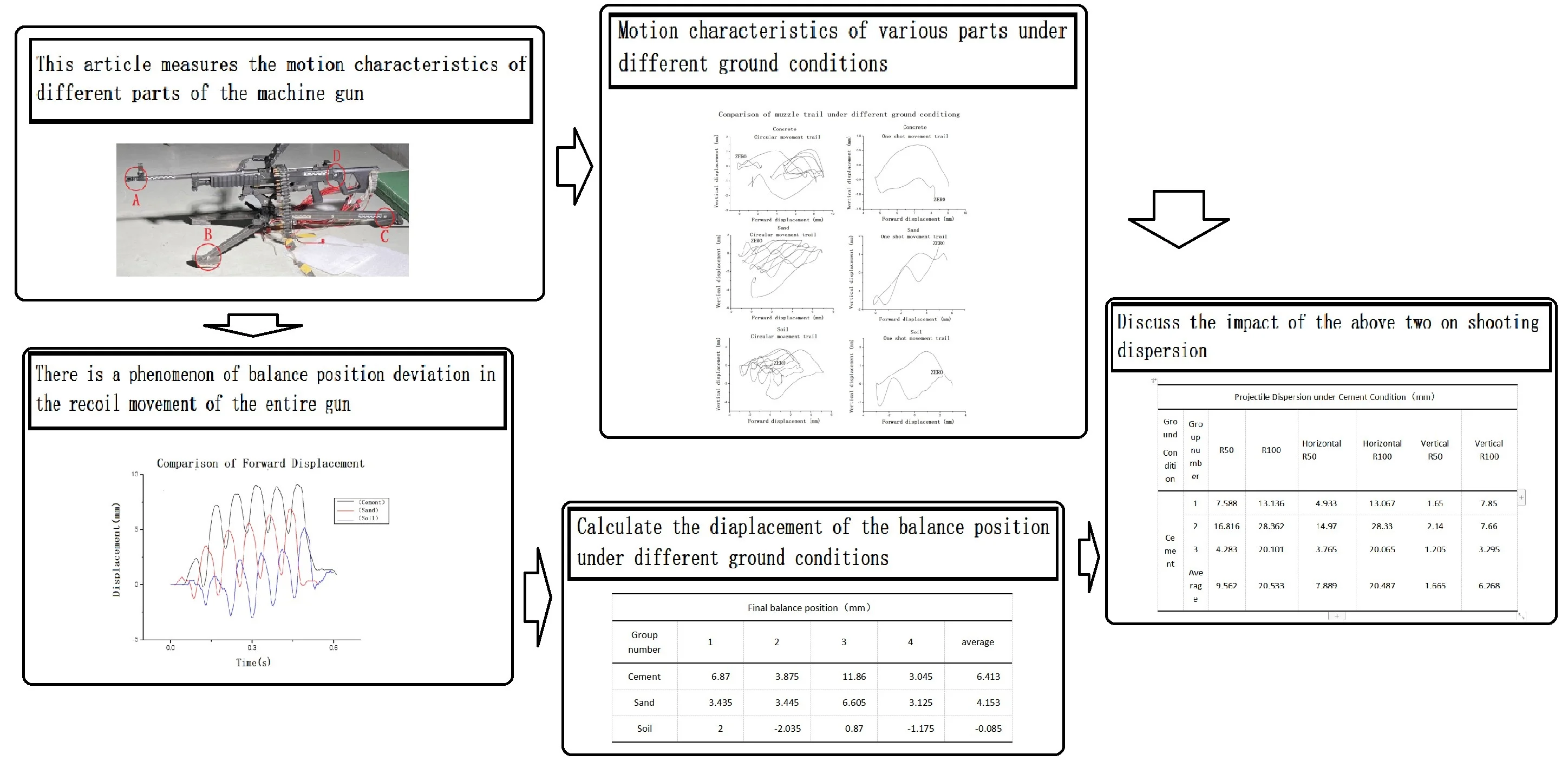
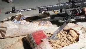
The selected typical machine gun is shown in Fig. 1. (All images in this paper were taken and produced by the author Liu Hengsha in the experiments involved in this paper).
Fig. 1Typical machine gun
As shown in the figure above, this typical machine gun adopts the air guiding automatic principle. The gun mount is a tripod, and the connection position with the gun body is close to the mass center of the gun body. The distribution of the tripod leg is two in the front and one in the rear, short in the front and long in the rear. The spade is of sled type, which can slide freely in the front and rear directions, and there are horizontal plates to prevent movement in left and right directions.
Position A is the muzzle, and its motion characteristics directly reflect the shooting accuracy. Positions B and C are the front tripod and the rear tripod respectively, which are in direct contact with the ground and reflect the movement characteristics of the gun rack. Position D is the butt of the gun, which together with the muzzle reflects the movement characteristics of the gun body.
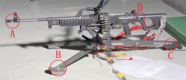
Three ground conditions are selected: cement, sand and soil. The cement ground is the ground of the test site, and the sand and soil are packed in sandbags. As shown in Fig. 2.
Fig. 2Ground condition
a) Cement
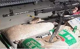
b) Sand
c) Soil
Among them, the cement is cast cement, which is very hard and the surface is relatively smooth. The sand is dry and loose, the particle volume is very small, and it is easy to slide between each other. The soil is dry and there are agglomerated particles of different sizes. The particles are relatively hard and irregular in shape, and it is not easy to slide between each other.
For cement floors, the tripod is placed on it, and for sand and soil floors, the tripod is inserted.
2.2. Load
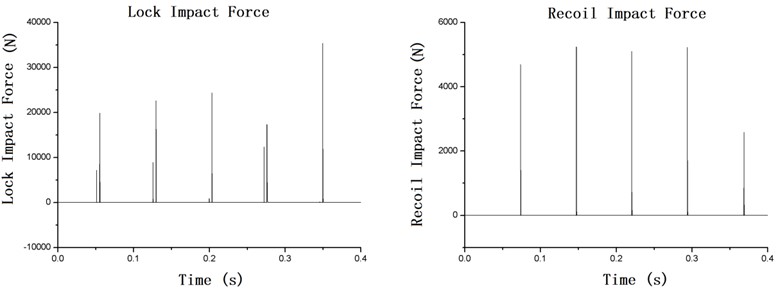
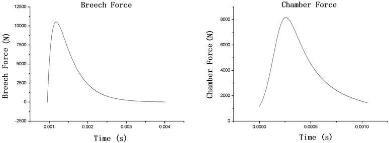
The loads in the firing process of a typical general machine gun mainly include the impact of the bolt when it locks, the pressure of gunpowder gas on the breech and gas chamber, and the impact of the bolt on the casing when it recoil. The former mainly causes the forward translation and forward turnover of the gun, followed by the jump of muzzle, and the latter mainly causes the backward translation and backward turnover of the gun.
Among them, the impact force is calculated by the existing simulation, and the breech force and chamber force are calculated by the internal ballistic formula according to the existing internal ballistic parameters.
The lock impact force and recoil impact force in continuous firing are shown in Fig. 3.
Fig. 3Lock impact force and recoil impact force
The breech force and chamber force in each shot are shown in Fig. 4.
Fig. 4Breech force and chamber force
2.3. Measuring method
2.3.1. Methodology
The principle of high-speed photogrammetry is to record the relative position of the target object relative to the camera at each time and compare it with the relative position at the next time to obtain the relative displacement. Through scale calibration, the actual distance corresponding to each unit of relative displacement is obtained. Then the actual displacement of the target object is calculated. According to the time interval between frames, the velocity of the target object are calculated.
The measurement accuracy of this method is determined by the length of each pixel, and the length of pixel is affected by lens parameters and shooting parameters. It can be calculated according to the measuring scale. In this experiment, the length of each pixel is about 0.2 mm.
2.3.2. Equipment
Table 1Test equipment
System | Equipment | Quantity |
Shooting system | General machine gun | 1 |
Bullet | 400 | |
Tripod | 1 | |
High speed photography system | High speed camera | 2 |
Camera lens | 2 | |
High speed camera tripod | 2 | |
Ruler and mark point | some | |
Master computer | 1 | |
DC lamp | 1 | |
Router | 1 |
2.3.3. Data processing
The key parameters are as follows: resolution: 512×384; sampling frequency: 5000 frames / second; Exposure time: 30 μ s.
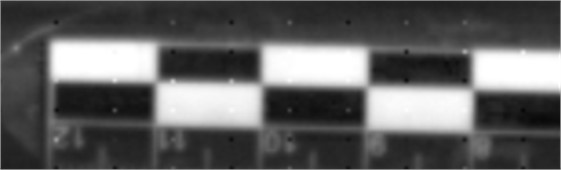
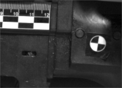
Calculate the length of each pixel with a scale, get displacement curve. the scale is shown in Fig. 5.
The time interval between every two frames is calculated as 0.2 μs according to the frame frequency.
Calculate the velocity curve of the target according to the displacement and time interval, and take the derivative of velocity curve to get the acceleration curve.
Fig. 5Scale
2.4. Experimental scheme
Three sets of shots are fired under each ground condition. Each group has four spot shots (five shots in a row), and one group has a total of 20 shots. After each group completes shooting, replace the target paper and record. A total of nine groups, 180 shots.
In terms of high-speed photogrammetry, two high-speed cameras are used to shoot muzzle-front tripod, muzzle-rear tripod and muzzle-butt respectively for three groups of shots under each ground condition. Then the displacement and velocity are obtained.
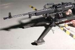
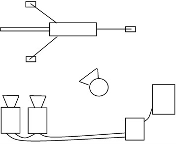
The equipment arrangement is shown in Fig. 6.
Fig. 6Equipment arrangement
The marker points and ruler arrangement is shown in Figs. 7-10.
Fig. 7Location of muzzle marking points
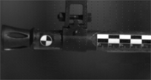
Fig. 8Location of sign points of front tripod
3. Test results and analysis
3.1. Motion characteristics of each part
In order to analyze the vibration response of the gun body and tripod more carefully, four position points are selected. Therefore, it is necessary to understand the vibration response form of these four locations and the correlation between them.
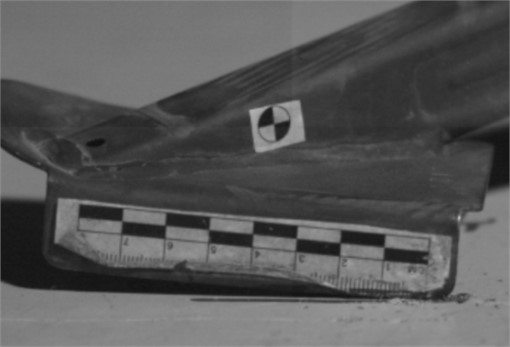
Fig. 9Location of rear tripod mark point
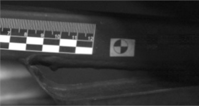
Fig. 10Location of butt marker points
Take the results of sand ground conditions as an example to illustrate the displacement and velocity characteristics of muzzle, front tripod, rear tripod and butt, as shown in Figs. 11-14.
Fig. 11Displacement and velocity curve of muzzle
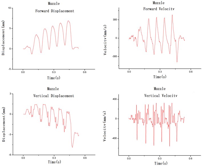
Fig. 12Displacement and velocity curve of front tripod
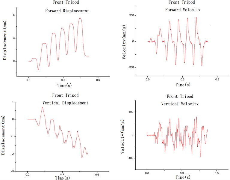
Fig. 13Displacement and velocity curve of rear tripod
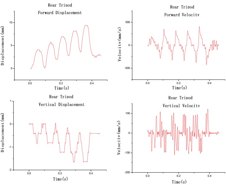
Fig. 14Displacement and velocity curve of butt
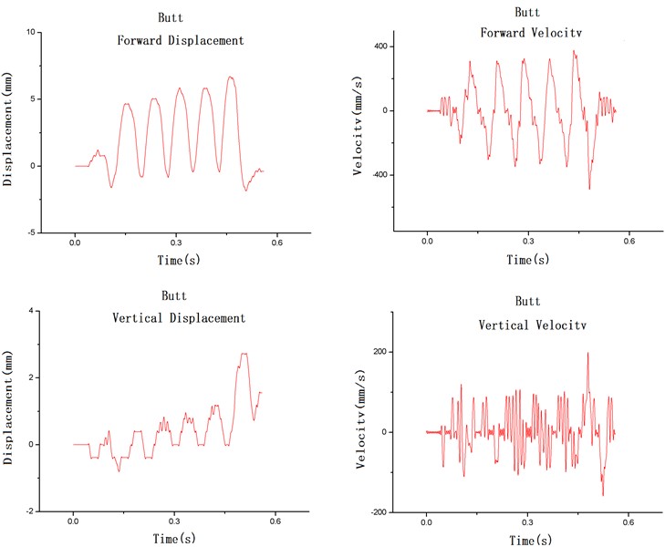
On the whole, the displacement velocity curves of each parts show the same trend, different details and different values of displacement velocity. There is a backward offset in the front and rear direction and a downward offset in the vertical direction. The single cycle displacement amplitude in the front and rear direction is between 4 mm and 7 mm, and the maximum speed is between 250 mm/s and 400 mm/s. The single cycle displacement amplitude in the vertical direction is between 1 mm and 3 mm, and the maximum speed is between 50 mm/s and 250 mm/s.
On this basis, the translation and pitching movement of the gun can be analysed by combining the movement of each position point.
3.2. Comparison of gun pitching motion response under different ground conditions
The pitching quasi-periodic motion is the main factor affecting the dispersion of projectile in the vertical direction. Due to the elastic deformation of the gun mount, the pitching of the gun body and the pitching of the gun mount are considered separately. The line between the muzzle and the butt mark points represents the gun body, and the line between the front and rear tripod mark points represents the gun mount. The inconsistency of the pitching degree between the two represents the elastic deformation of the gun mount.
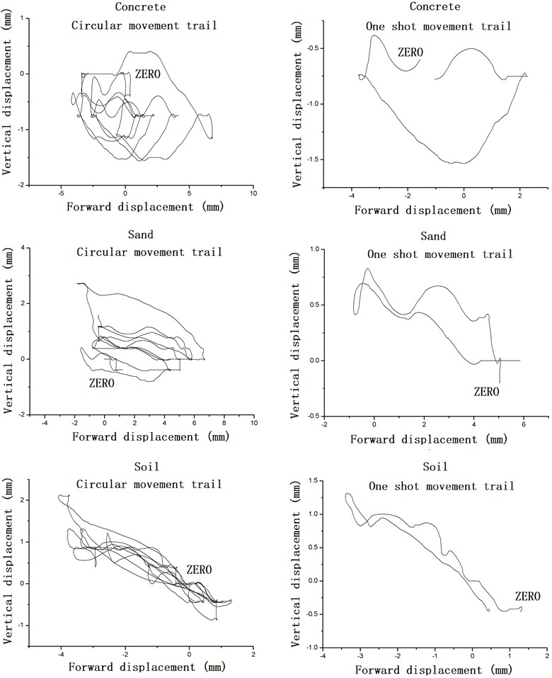
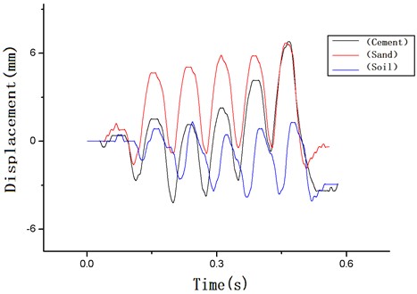
The plane is composed of front-and-back direction and up-and-down direction, and the motion trajectories of each part on the plane is obtained. Compare the different trajectories of each part under different ground conditions, the pitching movement of the gun can be seen. As shown in Figs. 15-18.
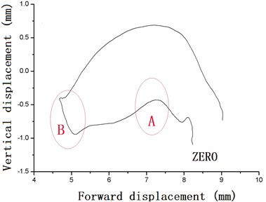
Take the single movement trajectories of cement ground as an example, as shown in Fig. 19.
The starting point is from the return of the bolt, the gun translates and Pitch down. Section A is the firing position, and there is a shaking peak at the muzzle, but it fails to change the movement trend of the gun. Section B is the recoil impact position, and the gun starts to translate and Pitch up.
The projection distance between the muzzle and butt marks is 900.1311 mm, and the projection distance between the front and rear tripod marks is 947.0739 mm. The two are similar, so in comparison, the displacement of each part in the up and down direction can be used to characterize the amplitude of pitching motion.
It can be seen from the figure that under the condition of cement ground, in a single firing cycle, the muzzle height movement amplitude in the forward stage is about 0.5 mm, and the muzzle height movement amplitude in the backward stage is about 1.3 mm, and the motion trajectory is mainly above the initial position.
Fig. 15Comparison of muzzle trajectories under different ground condition
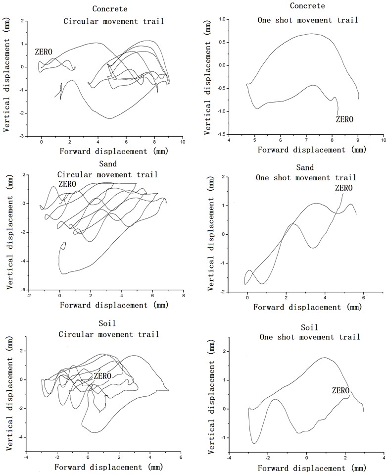
Fig. 16Comparison of front tripod trajectories under different ground condition
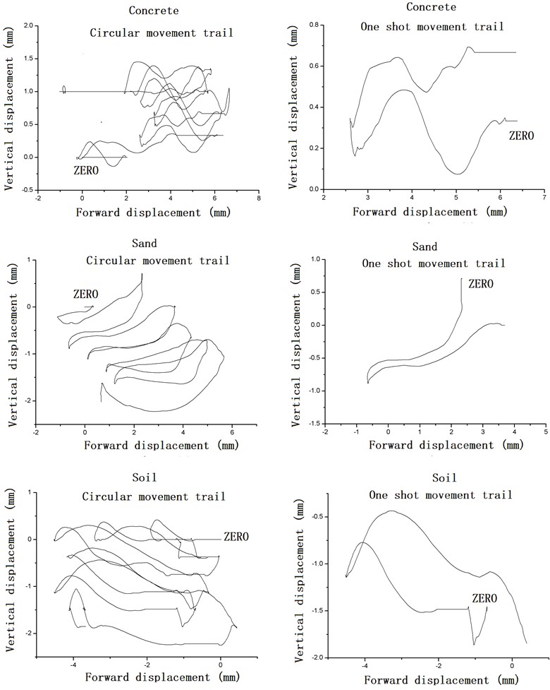
Analyze the motion trajectory of each part. Under the condition of cement ground, the gun mainly pitch up relative to initial position. The pitching amplitude of muzzle-butt is larger than that of the front and rear tripods, which indicates that the tripod has large elastic deformation. The gun rely more on elastic deformation of the gun mount to counteract pitching motion.
Under the sand ground condition, in a single firing cycle, the muzzle height movement amplitude in the forward stage is about 3 mm, and the muzzle height movement amplitude in the backward stage is about 2.5 mm. The motion trajectory is mainly below the initial position.
Analyze the motion trajectory of each part. Under the condition of sand ground, the gun mainly pitch down relative to initial position. The front and rear tripods also have a large pitching amplitude. It indicates that the deformation of the gun mount is relatively small and the ground deformation is relatively large. The gun rely more on ground deformation to counteract pitching motion.
Under the soil ground conditions, the muzzle height movement amplitude in the forward stage is about 1.5 mm, and the muzzle height movement amplitude in the backward stage is about 1.6 mm. The motion trajectory is both above and below the initial position.
Based on the analysis of the motion trajectories of various parts, under the soil ground conditions, the gun pitch both down and up relative to initial position. The pitching amplitude of the front and rear legs indicates that the deformation of the soil is small, and the gun mount also has elastic deformation. The gun rely on both elastic deformation of the gun mount and ground deformation to counteract pitching motion.
The soil can better prevent the machine gun vibration to the side and forward, and better hold the balance potion of vibration.
Fig. 17Comparison of rear tripod trajectories under different ground condition
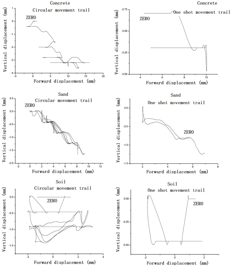
Fig. 18Comparison of butt trajectories under different ground condition
3.3. Comparison of translational motion response under different ground conditions
Take the forward and backward movement as an example. The translational motion response is composed of two parts, one is elastic vibration part, and the other is rigid body motion part.
The elastic vibration part comes from the elasticity of the gun mount, the elasticity of the shoulder and the elasticity of the ground. This part offsets the recoil impulse through the elastic vibration. The magnitude of the elastic vibration can be expressed by the vibration amplitude relative to the vibration balance position.
The rigid body motion part comes from the tripod slides relative to the ground, the ground deforms and the shooter's posture changes. The rigid body motion part offsets the recoil impulse through friction and deformation. The value of rigid body motion part can be expressed by the offset of the vibration balance position.
The two are mixed together. Therefore, in order to compare the vibration amplitude under different ground conditions, it is necessary to consider the offset of the vibration balance position before calculating the vibration amplitude.
Fig. 19Concrete. One shot movement trail example
The forward and backward displacement of each part under different ground conditions is shown in Figs. 20-23.
Fig. 20Comparison of muzzle forward displacement
Fig. 21Comparison of front tripod forward displacement
Fig. 22Comparison of rear tripod forward displacement
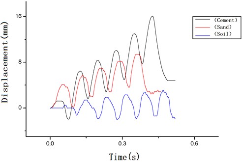
Fig. 23Comparison of butt forward displacement
It can be seen from the figure that there are two forms of displacement of the vibration balance position, one is a single large displacement, the other is a small number of multiple offsets, and the overall displacement is the result of multiple accumulation. The total offset can be expressed by the distance between the last vibration balance position and the initial position.
The final balance positions of the forward and backward movement displacement of each part under different ground conditions are obtained, as shown in Table 2. The size of the offset in each group of shooting has a certain randomness. The average value is calculated and compared.
Table 2Comparison of final balance positions
Final balance position (mm) | |||||
Group number | 1 | 2 | 3 | 4 | Average |
Cement | 6.87 | 3.875 | 11.86 | 3.045 | 6.413 |
Sand | 3.435 | 3.445 | 6.605 | 3.125 | 4.153 |
Soil | 2 | –2.035 | 0.87 | –1.175 | –0.085 |
It can be seen from the above that in the front and rear directions, the offset of the balance position under the cement ground is the largest, with an average of 6.41 mm, the offset of the sand ground is small, with an average of 4.15 mm, and the offset of the soil ground is the smallest, with an average of –0.085.
Combined with the displacement of vibration balance position, the average value of front and rear motion amplitude of each group under different ground conditions is obtained, as shown in Table 3.
Table 3Comparison of average vibration amplitude under different ground conditions
Average value of vibration amplitude (mm) | |||||
Group number | 1 | 2 | 3 | 4 | average |
Cement | 4.23 | 3.58 | 6.334 | 5.72 | 4.97 |
Sand | 5.35 | 3.91 | 4.74 | 6.2 | 5.05 |
Soil | 5.05 | 3.88 | 4.09 | 4.22 | 4.31 |
It can be seen from the table that under the sand ground conditions, the average amplitude of elastic vibration in the front and rear directions in the four groups is greater than that under the soil ground conditions.
Under the condition of cement ground, the average value of motion amplitude has great randomness. By comparing the curve, it can be seen that under the cement ground, when the offset of equilibrium position is a large offset, the average value of motion amplitude is lower, and when the offset of equilibrium position is multiple and small offsets, the average value of motion amplitude is larger.
3.4. Comparison of projectile dispersion under different ground conditions
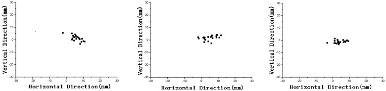
The impact points under different ground conditions are compared, as shown in Figs. 24-26.
Fig. 24Projectile dispersion under cement condition
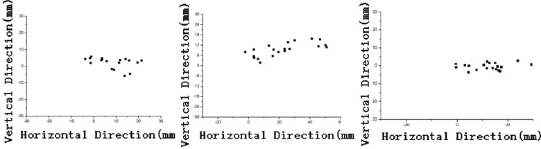
Fig. 25Projectile dispersion under sand condition
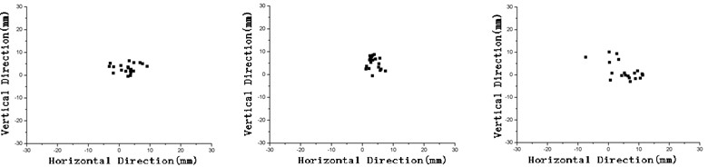
Fig. 26Projectile dispersion under soil condition
Calculate and compare the firing dispersion under different ground conditions, as shown in Tables 4-6.
Shooting dispersion is represented by R50 and R100. R50 refers to the circle radius of the area with 50 % probability of the point of impact, and R100 refers to the circle radius of the area with 100 % probability of the point of impact.
Table 4Projectile dispersion under cement condition
Projectile dispersion under cement condition (mm) | |||||||
Ground condition | Group number | R50 | R100 | Horizontal R50 | Horizontal R100 | Vertical R50 | Vertical R100 |
Cement | 1 | 7.588 | 13.136 | 4.933 | 13.067 | 1.65 | 7.85 |
2 | 16.816 | 28.362 | 14.97 | 28.33 | 2.14 | 7.66 | |
3 | 4.283 | 20.101 | 3.765 | 20.065 | 1.205 | 3.295 | |
Average | 9.562 | 20.533 | 7.889 | 20.487 | 1.665 | 6.268 | |
Table 5Projectile dispersion under sand condition
Projectile dispersion under sand condition (mm) | |||||||
Ground condition | Group number | R50 | R100 | Horizontal R50 | Horizontal R100 | Vertical R50 | Vertical R100 |
Sand | 1 | 3.215 | 6.454 | 1.9 | 6.4 | 1.265 | 3.565 |
2 | 2.855 | 5.633 | 1.25 | 3.75 | 2.085 | 5.615 | |
3 | 4.954 | 14.234 | 3.475 | 12.825 | 2.225 | 8.475 | |
Average | 3.675 | 8.774 | 2.208 | 7.658 | 1.858 | 5.885 | |
Table 6Projectile dispersion under soil condition
Projectile dispersion under soil condition (mm) | |||||||
Ground condition | Group number | R50 | R100 | Horizontal R50 | Horizontal R100 | Vertical R50 | Vertical R100 |
Soil | 1 | 2.365 | 9.119 | 1.94 | 8.06 | 1.135 | 4.635 |
2 | 3.66 | 7.160 | 3.05 | 6.85 | 0.785 | 4.315 | |
3 | 2.881 | 7.481 | 2.37 | 7.43 | 0.825 | 2.525 | |
Average | 2.969 | 7.920 | 2.453 | 7.447 | 0.915 | 3.825 | |
It can be seen from the above table that the projectile dispersion under the cement ground condition is the largest, reaching 20.53 mm, the projectile dispersion under the sand and soil conditions is relatively close, and the soil condition dispersion is slightly smaller, 8.77 mm and 7.92 mm respectively.
In terms of horizontal dispersion, the horizontal dispersion of cement condition is very large, reaching 20.48 mm, and the sand and soil are similar, which are 7.65 mm and 7.44 mm respectively.
In the horizontal direction, the horizontal plate at the bottom of the hoe is mainly used to prevent the horizontal movement of the gun. The horizontal plate has no effect on the cement floor, so its horizontal dispersion is very large. Under the conditions of sand and soil, the translational stability of counteracting lateral movement is close, and sand is slightly better than soil.
In the vertical dispersion, the maximum cement is 6.27 mm, the second is sand, which is 5.88 mm, and the minimum soil is 3.82 mm.
The main factor affecting the vertical dispersion is the stability of gun overturning, which indicates that the stability of overturning motion under the soil ground condition is the best, the sand ground condition is the second, and the cement ground condition is the worst.
4. Conclusions
1) The displacement and velocity responses of muzzle, front tripod, rear tripod and butt during continuous firing under ground conditions of cement, sand and soil are obtained for a typical machine gun. All parts are subject to periodic vibration, and the vibration balance position is offset. The vibration characteristics of each part is basically the same, and the amplitude is different.
2) The pitching motion response of a typical machine gun under different ground conditions is compared. Under the condition of cement ground, it mainly pitch upward relative to initial position, which relies more on the elastic deformation of the gun mount to offset part of the muzzle jump, and the ability to restore the initial position is poor. Under the condition of sand ground, it mainly pitch down relative to initial position, which depends more on the ground deformation to absorb pitching energy. Under soil conditions, it pitch both upward and downward relative to initial position, which rely on the elastic deformation of the gun mount and the ground deformation to offset the pitching movement, and the ability to restore the initial position is the best.
3) The translational motion response of a typical machine gun in the front-and-back direction under different ground conditions is compared, which is divided into the vibration of the elastic part and the displacement of the inelastic part. The amplitude of translational vibration under sand condition is larger than that under soil ground condition, with an average of 5.05 mm and 4.31 mm respectively. The amplitude of translational vibration under cement condition is random and affected by inelastic displacement, with an average of 4.97 mm. In the front and back directions, the maximum offset is 6.41 mm on average under cement conditions, the small offset is 4.15 mm on average under sand conditions, and the minimum offset is –0.085 mm on average under soil conditions.
4) The firing dispersion under different ground conditions is compared. In terms of horizontal dispersion, the horizontal dispersion of cement condition is very large, reaching 20.48, and the sand and soil are similar, which are 7.65 and 7.44 respectively. Under the condition of cement, the lateral translation stability is very poor. In terms of vertical dispersion, the cement condition dispersion is the largest 6.27 mm, the sand condition dispersion is the second 5.88mm, and the soil condition dispersion is the smallest 3.8 mm. The turnover stability of soil is the best, followed by sand and cement.
5) To sum up, under the soil and ground conditions, the machine gun has the best stability when firing. Because the soil can better prevent the machine gun vibration to the side and forward, and better hold the balance potion of vibration.
References
-
R. Wang, R. Cheng, and Y. Hao, “Principle and practice of dynamic stability of machine gun,” Journal of Nanjing University of Science and Technology, Vol. 3, pp. 265–268, 2004, https://doi.org/10.14177/j.cnki.32-1397n.2004.03.010
-
Y. Cheng, “Design of elastic gun holder and analysis of weapon firing dispersion accuracy,” Small Arms, Vol. 6, pp. 18–21, 1996.
-
R. Wang, Y. Li, and J. Zhang, “Design of a machine gun mount with buffer-type spade,” Binggong Xuebao, Vol. 28, No. 2, pp. 144–147, 2007.
-
J. Zhang, L. Shang, Y. Li, and X. Kang, “Research on structural design parameter optimization of machine gun mount with buffer-type spade,” Journal of North University of China (Natural Science Edition), Vol. 32, No. 3, pp. 276–279, 2011.
-
Zhou Ding, “Vibration analysis of machine gun with elastic frame,” Mechanics in Engineering, Vol. 1, pp. 47–50, 1992.
-
J. Wang and D. Zhou, “Study on the influence of gun body elasticity on the vibration characteristics of machine gun,” Journal of Nanjing University of Science and Technology, Vol. 6, pp. 575–578, 2001, https://doi.org/10.14177/j.cnki.32-1397n.2001.06.004
-
Y. Qi, S. Luo, X. Guan, and C. Xun, “Study of adaptability of a flexible to two crew served weapons,” Journal of Gun Launch and Control, Vol. 37, No. 3, pp. 1–5, 2016, https://doi.org/10.19323/j.issn.1673-6524.2016.03.001
-
C. Yang, K. Zhou, Q. Liu, and Lu Ye, “Effect of cross section shape of tripod legs on firing stability of machine gun,” Journal of Ordnance Equipment Engineering, Vol. 42, No. 12, pp. 87–91, 2021.
-
J. Chen, R. Wang, T. Li, and X. Yang, “Design of machine gun articulated buffer type parking hoe,” Journal of Machine Design, Vol. 29, No. 4, pp. 36–38, 2012, https://doi.org/10.13841/j.cnki.jxsj.2012.04.017
-
X. Han, F. Zhao, M. Yang, and S. Zhou, “A new type design of machine gun mount based on floating technology,” Ordnance Industry Automation, Vol. 30, No. 8, pp. 7–9, 2011.
-
Q. Cao, “Discussion on the influence of soil on weapon firing stability,” Journal of Nanjing University of Science and Technology, Vol. 3, pp. 171–178, 1982, https://doi.org/10.14177/j.cnki.32-1397n.1982.03.015
-
Z. Fan, R. Wang, and Y. Li, “Ground adaptability analysis of a large calibre machine gun,” Journal of Gun Launch and Control, Vol. 37, No. 1, pp. 21–26, 2016, https://doi.org/10.19323/j.issn.1673-6524.2016.01.005
-
H. Liu, Y. Zheng, W. Li, Q. Zhang, W. Yao, and G. Liu, “Velocity measurement method of projectiles based on high-speed photography technology,” Ordnance Industry Automation, Vol. 33, No. 11, pp. 71–74, 2014.
-
R. Xu, G. Yang, Q. Chen, X. Wang, J. Ge, and Q. Sun, “Error analysis of high speed photography in measuring kinematic parameter of artillery,” Journal of Nanjing University of Science and Technology, Vol. 39, No. 5, pp. 523–530, 2015, https://doi.org/10.14177/j.cnki.32-1397n.2015.39.05.003
About this article

The author thanks NJUST for providing the experimental gun. Thanks for the test equipment provided by the teaching and research office. Thanks for the test site provided by Tangshan experimental base. Thanks to the tutor Xucheng for his guidance on research ideas and teacher Cao Yanfeng for providing on-site support for the experiment. Thanks to Wang Yang and other students for their assistance in the experiment. This paper is supported by the National Natural Science Foundation of China (No. 52275256).
The datasets generated during and/or analyzed during the current study are available from the corresponding author on reasonable request.
Mr Liu Hengsha formulated the research idea and the test plan, managed and completed the test, analysed the test data, and obtained the conclusions. Mr He Long participated in the test process and was responsible for processing a part of the data to support the conclusion. Mr Xu Cheng provided valuable guidance for the formulation of research ideas and test plans. Discuss and assist in adjusting the structure of the article for many times, supplement details and improve the conclusion.
The authors declare that they have no conflict of interest.
