Abstract
In order to know well the vibration law on influence of ground vibration on instrument support in gun firing process, a measuring method for the vibration response of the instrument support based on the principle of acceleration measurement is presented. The instrument support is arranged on the ground. When the gun fires, the acceleration response of the instrument support is measured. The vibration velocity and vibration displacement responses of the support can be obtained by the integral operation of the acceleration. The results show that when the gun fires with single shot and the period of the projectile in-bore motion, the vibration response of the instrument support caused by ground vibration is very small, and it can be ignored. When the projectile moves outside the bore, the ground vibration has a significant influence on the vibration of the instrument support. The vibration response of the instrument support in the range of muzzle shock wave is mainly caused by the muzzle shock wave.
1. Introduction
When the gun fires, it not only causes the strong vibration of the gun structure itself, but also causes the ground vibration. The vibration responses include the vibration responses of the muzzle, elevation part, rotating part and chassis, etc. The gun vibration not only affects the reliability of the gun work, but also affects the firing accuracy of the gun more. A general, when the gun vibration response is large, then firing accuracy is poor. In order to verify the effect of gun design, carry out fault diagnosis, and know the law of the gun vibration, the gun vibration measurement must be carried out. Therefore, the gun vibration measurement plays an important role in the development of gun weapons [1].
Vibration measurement of gun structure is often carried out during gun firing. In most cases, measuring instruments are often arranged on the ground. The non-contact or contact method is used to detect the vibration response of gun structures. In the literature [2], 3 aspects from measuring equipment, measuring environment and practice, the influences of high speed camera, optical lens, light transmission, vibration, light, photographic exposure time, coordinate calibration and other factors on the measuring errors are discussed. In view of the above factors, the methods of reducing errors are designed. After the projectile has been fired for 80 ms, the ground vibration caused by the gun firing is sensed by high-speed camera away from gun 30 m. In the literature [3], the current measurement methods of projectile in-bore motion posture, including high-speed photography, laser optical lever method, etc., are described at home and abroad. The principle of measurement is that the laser outside the barrel beams the mirror in front of the gun. After the laser beam is reflected by the projectile head mirror, it is returned to the image screen on the ground by the original path. The laser spot displacement at the image screen is recorded by a high speed camera on the ground or a photoelectric detector, respectively. Thus, the bore posture of the projectile is obtained. In the literature [4], a method of muzzle disturbance measurement based on photoelectric position sensor is proposed. The photoelectric position sensor is placed on the ground, and a flat mirror is fixed on the muzzle. In this way, the muzzle angular displacement of the gun during firing is obtained. From the literatures [5-7], the high speed cameras are arranged on the ground, the projectile velocity and muzzle vibration displacement were measured, respectively. From the literatures [8-10], based on the eddy current displacement sensor, photoelectric displacement follower, laser vibrometer and laser CCD displacement sensor, the measurement methods of muzzle displacement are described. The sensors are arranged on the ground, the muzzle vibration displacements are obtained by non-contact method.
Analysis of the above literatures shows that, when measuring the vibration responses of gun, the measuring instruments are often arranged on the ground, and the results obtained are the relative responses of the gun structure measurement point relative to the ground. The effects of ground vibration on the measuring instrument support are not mentioned in the above literatures. But gun designers are very concerned about the problem, because excessive ground vibration affects the accuracy of the measuring instrument. When the ground vibration laws are known, the error analysis of gun vibration measuring results can be correctly made, and he laws of gun vibration measurement are more reliable.
The course of gun firing can cause ground vibration, and the ground vibration will cause the vibration of the instrument support, the vibration of the instrument support will introduce the sensor output error. The ground vibration and instrument support vibration are inherent and cannot be avoided. When the instrument support vibration is very small, the measuring error introduced by it can be neglected. On the other hand, when the vibration of the instrument support is large, the measurement error introduced by it should be paid attention to. At present, when people carry out gun vibration response measurement, because the instrument support vibration laws are complex, and the error caused by ground vibration is sometimes acceptable, therefore, the vibration of instrument supports is not taken into consideration. It is considered that the vibration response of the instrument support is very small and can be neglected in the gun firing process. How about the actual situation? People have been asking the same question for years. But there is no sure answer at the moment.
In order to know the laws of ground vibration caused by gun firing, to provide an effective measuring data for error analysis based on instrument support vibration, in this paper, a measurement method of ground vibration response based on acceleration measuring principle is proposed. The instrument supports are arranged on the ground. When the gun fires, the acceleration response of the instrument support is measured. When the acceleration signal passes through the one or two signal integral operation, the vibration velocity and vibration displacement responses of the instrument support are obtained, and ground vibration laws are obtained by data analysis. Using the inertial measuring principle, the introducing measuring method errors again are avoided.
2. Measuring method
The large caliber artillery is chosen as the test object, as shown in Fig. 1. On the right side of the gun, the point is chosen as the ground measuring point, the distance frompoint to muzzle is 5 m, and the distance frompoint to tube is 0.5 m. The coordinate system, , is set up with point as coordinate origin. The axis forward along firing direction, the axis is pointing left, with the right hand rule, the axis is pointing up. Place an instrument support at thepoint and press it with heavy weights. In the instrument support, the acceleration sensors are fixed along the , , directions respectively. The acceleration responses of the instrument support along the orthogonal 3 directions due to the ground vibration caused by the gun firing are measured. After integral operation, the velocity and displacement responses of the instrument support caused by ground vibration, in 3 directions, can be obtained.
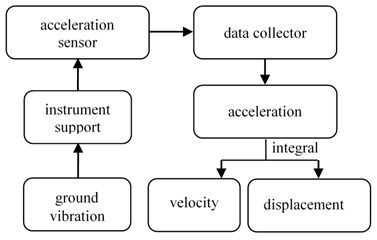
In the measuring system, there are 3 acceleration sensors, its measurement range is 50 g, its measurement accuracy is 5 %. The voltage range of constant current source is ±5 V, its measurement accuracy is 0.5 %. The output voltage of data collector is ±10 V, its measurement accuracy is 0.5 %. The power required by the sensors is provided by the constant current source, the output signals of the sensors are recorded, stored and processed by the data collector. Fig. 2 is a measuring principle block diagram of the influence of ground vibration on the instrument support for gun vibration measurement.
Fig. 1Sketch map of vibration response measuring point of instrument support based on ground vibration
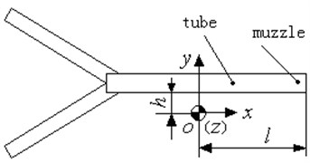
Fig. 2The measuring principle block diagram of the influence of ground vibration on the instrument support for gun vibration measurement
3. Measuring results
Large caliber gun is selected as the measuring object. Experimental research on the influence of ground vibration on the instrument support for the gun measurement is done. The acceleration sensors are fixed to the instrument support. In the direction of the , , axis, each of the axis is fixed with a sensor. The vibration responses of the instrument support due to ground vibration are measured by the sensors. The gun fires in single shot, at the same conditions, the firing process is repeated 5 shots. The vibration acceleration responses of the instrument support, caused by ground vibration, at points on the side of the gun, are measured. After integral operations to the acceleration signal are done, the vibration velocity response and the vibration displacement response of the instrument support are obtained.
3.1. Period of in-bore
The period of motion of the projectile in the tube is defined as the period of in-bore. The measuring results of the vibration acceleration, velocity and displacement responses of the instrument support, at the projectile exit time, are listed in Table 1. Where, variables , , represent the acceleration, velocity, and displacement of the instrument, in the direction, respectively. The variables units are g, mm/s and m, respectively. Meanings in the , direction have same representations like direction.
The measuring results show that, when selected the large caliber gun fires, in the period of in-bore and the projectile exit time, the statistical results of vibration response of instrument support caused by ground vibration, along the orthogonal 3 directions, are that the acceleration is less than 0.2 g, velocity is less than 4 mm/s, and displacement is less than 9.3 μm. Compared with the vibration response of the instrument support and the vibration response of the gun structure itself, the former is 2 or 3 orders of magnitude smaller than the latter. Therefore, at the moment of the projectile exit time, the vibration response of the instrument support is very small due to ground vibration.
Table 1The measuring results of the vibration response of instrument support (at the moment of the projectile exit time)
Pill No. | 1 | 2 | 3 | 4 | 5 | Average |
/ g | 0.1 | 0.1 | 0 | 0.1 | 0.1 | 0.08 |
/ (mm/s) | 3.0 | 2.0 | 2.8 | 4.0 | 3.8 | 3.12 |
/ μm | 9.0 | 4.0 | 5.0 | 8.1 | 7.0 | 6.62 |
/ g | 0.0 | 0.0 | –0.2 | –0.1 | –0.1 | –0.08 |
(mm/s) | –2.0 | –1.7 | –1.2 | –2.2 | –2.2 | –1.86 |
/ μm | –3.0 | –2.0 | –6.0 | –6.7 | –6.0 | –4.74 |
/ g | –0.1 | 0.0 | 0.0 | 0.0 | 0.0 | –0.02 |
(mm/s) | 2.0 | 2.3 | 2.3 | 3.5 | 3.4 | 2.7 |
/ μm | 8.0 | 8.0 | 5.0 | 9.3 | 9.0 | 7.86 |
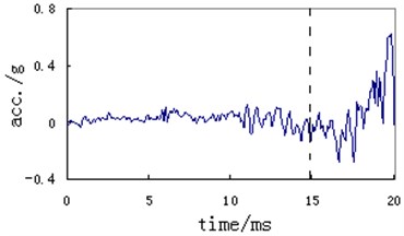
Figs. 3 to 5 are typical measuring curves for vibration responses of the instrument support caused by ground vibration, including displacement, velocity and acceleration. The vertical dashed line in the figure indicates the projectile exit time, the left side of the dashed line is the period of motion in the projectile in-bore (the same below).
Fig. 3Typical measuring curve of vibration displacement of instrument support (z direction, in-bore)
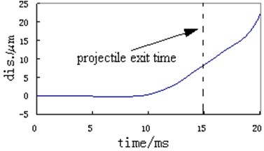
Fig. 4Typical measuring curve of vibration velocity of instrument support (z direction, in-bore)
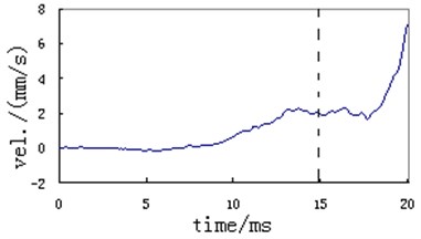
Fig. 5Typical measuring curve of vibration acceleration of instrument support (z direction, in-bore)
3.2. Period of out-bore
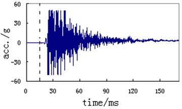
The period of motion of the projectile outside the bore is defined as the period of out-bore. When the projectile moves away from the bore, the projectile moves into the period of out-bore. After measuring, the measuring results of vibration acceleration response of instrument support during projectile motion outside the bore are obtained. Fig. 6 is a typical measuring curve of the vibration acceleration of the instrument support before and after the projectile exit time. Where indicates the projectile exit time, indicates, after the projectile goes out of the muzzle, the starting time of a sharp increase on acceleration, indicates the time of arrival of the muzzle shock wave at the instrument support. Fig. 7 is the typical measuring curves for vibration acceleration of the instrument support in the direction of theaxis.
Analyzed acceleration response measuring curve of instrument support, the results show that, in view of the selected gun and location of measuring point, after 5.17 ms that the projectile left the muzzle, the acceleration response of the instrument support is obviously increased gradually. During the period that projectile has left the muzzle for 5.17 ms-9.48 ms, the maximum acceleration response of the instrument support is less than 10 g. After the projectile has leave the muzzle for 9.48 ms, under the action of the muzzle shock wave, the acceleration response of the instrument support increases rapidly, its value exceeds 50 g. The acceleration response of the instrument support in the range of muzzle shock wave is mainly caused by the muzzle shock wave, it is 10 times higher than that caused by the ground vibration excitation response.
Fig. 6Typical measuring curve of vibration acceleration of instrument support (before and after the projectile exit time)
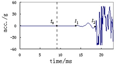
Fig. 7Typical measuring curve of vibration acceleration of instrument support (z direction, out-bore)
4. Conclusions
1) When gun fires, the ground vibration and instrument support vibration are inherent, and it is unavoidable.
2) When single firing and the projectile moves in the bore, the vibration response of the instrument support caused by ground vibration is very small and negligible. When the projectile is out of bore or the gun fires repeatedly, the ground vibration has important influence on the vibration of instrument support, and should be paid more attention to.
3) Compared with the ground vibration and the muzzle shock wave excitation, the vibration responses of the instrument support in the range of muzzle shock wave are mainly caused by the muzzle shock wave. The instrument support is closer to the muzzle, the more obvious the effect of the muzzle shock wave.
References
-
Wang Baoyuan, Heng Gang, Zhou Faming, et al. Progresses of A Measurement Technology of Gun. National Defense Industry Press, Beijing, 2011, (in Chinese).
-
Xu Rui, Yang Guolai, Chen Qiang, et al. Error analysis of high speed photography in measuring kinematic parameter of artillery. Journal of Nanjing University of Science and Technology, Vol. 39, Issue 5, 2015, p. 523-530, (in Chinese).
-
Guo Zecheng, Chen Ming, Zhang Feimeng Measurement methods of the motion posture of projectile in-bore in half restrained period. Ordnance Industry Automation, Vol. 32, Issue 3, 2013, p. 72-75, (in Chinese).
-
Zhang Zhiquan, Zhu Qi, Ding Sheng, et al. A measurement method of muzzle disturbance based on PSD. Journal of Academy of Armored Force Engineering, Vol. 26, Issue 2, 2012, p. 49-53, (in Chinese).
-
Zhao Fuquan, Cong Mengkai, Zhang Haiyong Dynamic test of small caliber gun based on high speed video. Electronic Measurement Technology, Vol. 34, Issue 10, 2011, p. 80-82, (in Chinese).
-
Li Shili, Guo Min, Du Wenbin, et al. Measurement of tank gun muzzle vibration based on image processing with high sub-pixel precision. Journal of Test and Measurement Technology, Vol. 31, Issue 2, 2017, p. 131-136, (in Chinese).
-
Wang Baoyuan, Zhang Pengfei, Chao Hongxiao, et al. Study on measurement technique of muzzle vibration displacement with high speed digital imaging method. Journal of Test and Measurement Technology, Vol. 28, Issue 5, 2014, p. 413-417, (in Chinese).
-
Wang Baoyuan, Shao Xiaojun Summarization of the measurement method for muzzle vibration responses. Journal of Gun Launch and Control, Vol. 31, Issue 3, 2010, p. 112-116, (in Chinese).
-
Chen Yanhui, Guo Min, He Zongying, et al. Muzzle vibration test method and practice. Journal of Gun Launch and Control, Vol. 31, Issue 1, 2010, p. 80-83, (in Chinese).
-
Wang Baoyuan, Xu Yaofeng, Zhou Faming, et al. Effect of muzzle vibration on vertical target dispersion. Journal of Vibration and Shock, Vol. 33, Issue 8, 2014, p. 83-87, (in Chinese).
About this article

