Abstract
In order to solve the problem of muzzle vibration displacement test of large caliber under high elevation, this paper presents a test method by two high-speed photography. The method fully considers the influence of the muzzle torsion on the measurement results, and accurately obtains the three-dimensional vibration displacement of the muzzle of the large caliber artillery. Finally, through the result analysis, the accuracy of the measurement results can reach 0.1 mm, which shows the advantage of the sub-pixel-based high-speed camera processing method in the muzzle vibration displacement test of the conventional artillery. This paper proposes an innovative test method that accurately measures the vibration displacement of the muzzle using a non-contact method.
1. Introduction
For large-caliber artillery, the vibration displacement of the muzzle is the main feature affecting the intensity of the artillery [1, 2]. Due to the harsh environment around the muzzle of large caliber artillery, the non-contact method is mainly used for the vibration displacement test of large caliber artillery muzzle. For example, eddy current displacement sensor, photoelectric displacement follower, CCD laser displacement sensor, PSD detector, and high speed photography [3, 4]. A disadvantage of the eddy current displacement sensor is that the measurement range is small. The disadvantage of the photoelectric displacement follower is that it is susceptible to weather and light. And CCD laser displacement sensor and PSD detector are easily affected by smoke and flame when the gun is fired [5, 6].
High speed photography is a non-contact test method widely used in recent years. This method uses a high-speed camera to capture the muzzle motion video when the projectile is fired. The muzzle vibration displacement measurement is then implemented by digital image processing technology. This method has the advantages of high test accuracy and being less susceptible to environmental influences. In this paper, a 155 mm artillery is taken as the research object, and a method for measuring the vibration displacement parameters of large-caliber high-angle artillery muzzle with double high-speed camera is proposed. According to the method, the vibration displacements of the artillery muzzle up and down, left and right, and front and back are obtained at an angle of 45°. The method fully considers the influence of the body tube torsion on the muzzle vibration measurement when the artillery is fired. Through the test verification, the measurement results are in accordance with the vibration law of the artillery muzzle, and the measurement accuracy meets the vibration displacement test requirements of the large-caliber artillery muzzle.
2. The principle of test
When the artillery is fired, the artillery muzzle will have vibration displacements in the up, down, left and right directions [7]. The muzzle vibration displacement is shown in Fig. 1. According to the theory of elastic dynamics [8, 9], during the movement of the projectile in the bore, the barrel generates axial vibration, torsional vibration, and lateral vibration, and the vibrations in all directions are coupled to each other.
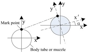
Firstly, a special marker point for image recognition is attached to the outer surface of the muzzle, and then high-speed cameras are used to capture the moving image of the marker point of the muzzle portion during the movement of the projectile. At the end of the shooting, the marker points of the captured muzzle parts are tracked by digital image processing technology to obtain the vibration displacement of the marker points. In the test, the image coordinate axis needs to be aligned with the muzzle vibration displacement direction.
In the vibration displacement test of large-caliber artillery muzzle, the test method based on high-speed camera system has great application potential. As long as the appropriate position, lens, and appropriate tracking algorithm are selected, the muzzle vibration displacement can be accurately obtained.
Fig. 1Muzzle movement diagram
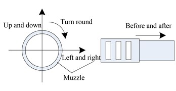
Fig. 2Marked point motion diagram
2.1. Introduction of test system
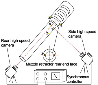
Under the high-angle shooting conditions of the large-caliber artillery, two high-speed cameras were placed alternately to measure the vibration displacement of the muzzle. Firstly, the high-speed camera recognition point 1 and the recognition point 2 are pasted along the axis direction of the body tube, as shown in Fig. 3. On the rear end face of the artillery retractor, high-speed camera recognition points 3 and 4 are respectively fixed. Recognition point 8 is attached to the central axis of the upper side surface of the body tube. The distance between the points 1 and 8 to the muzzle is equal, as shown in Fig. 4. Then, a high-speed camera was set up about 15 m from the side of the muzzle. By adjusting the field of view, attitude and focal length of the high-speed camera while observing the high-speed camera display interface, ensure that the body axis is parallel to the -axis of the high-speed camera. The high-speed camera marks 1 and 2 and the muzzle are clearly imaged in the side high-speed camera image.
Another high-speed camera was set up about 4 m behind the gun. Adjust the field of view, attitude and focal length of the high-speed camera to ensure that the gun barrel is perpendicular to the x-axis of the high-speed camera. The position of the high speed camera is shown in Fig. 5. Since two high-speed cameras are used in the test system, two high-speed cameras can be synchronously triggered with high-precision trigger signals, ensuring that two high-speed cameras have the same time reference.
Fig. 3Marking point on the side of the tube
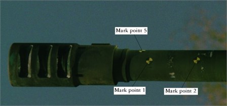
Fig. 4Marking point on the upper surface of the tube
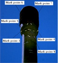
Fig. 5Muzzle vibration displacement range test schematic
2.2. Calibration of the test system
During the test, neither of the two high-speed cameras was a flat-view target. The presence of the shooting angle has an effect on the measurement results. In this paper, the high-speed camera test system is calibrated by the ruler to eliminate the error caused by the high-speed camera optical axis not perpendicular to the measurement target -axis. The principle of the system calibration is shown in Fig. 6. If the optical axis of the high-speed camera is perpendicular to the plane of the target, the number of pixels occupied by the scale is , and the object moves pixels. Then there is: , .
When the angle between the imaging surface of the high-speed camera and the plane being measured is . First, the camera is calibrated by selecting a scale that is consistent with the measurement direction on the measurement plane, that is, the correspondence between the distance and the pixel is obtained. Then, using the camera after calibration, the actual displacement of the object can be obtained.
The entire calibration process is done automatically by the image processing system. The calibration result can be obtained by measuring the distance between the two marks in the direction in advance and taking the image of the mark by a high-speed camera.
Certain principles need to be followed during the calibration process. The scale should be fixed on the plane of the target to be measured, and the direction of the scale should be consistent with the direction of displacement of the target.
Fig. 6System calibration diagram
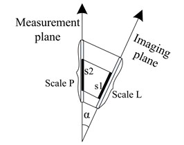
Fig. 7Schematic diagram of the muzzle twist angle
2.3. Test result processing
Observed from the perspective of the high-speed side view of the front side, the torsional displacement of the muzzle does not affect the displacement of the marker points 1 and 2 in the recoil direction.
If the recoil displacements of points 1 and 2 are and , the vibration displacement in the front and rear direction of the muzzle is:
The displacement of the marker point 1 in the direction is composed of the upper and lower vibration displacement and the torsional displacement of the muzzle. Then there is:
where is the vibration displacement of the muzzle in the up and down direction, and is the displacement component of the marker point 1 in the direction due to the torsional action.
The -direction displacement of the marker point 3 is composed of the vibration displacement in the left-right direction of the muzzle and the displacement due to the torsion, that is, .
Similarly, according to Fig. 5, , .
is the vibration displacement of the muzzle in the left and right direction, and is the displacement component of the marker point 3 due to the torsion in the direction. , and have similar meanings.
If the muzzle is twisted to a uniform twist, there is , then there is:
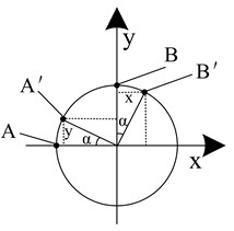
Assuming that the muzzle is evenly twisted, the torsion angle is , and the muzzle torsion is shown in Fig. 7.
As can be seen from Fig. 7, if the marker point is on the center line of the front side of the body tube, the marker point is on the center line of the upper surface of the body tube. Due to the muzzle twisting effect, the marker point is twisted to the marker point , and the marker point is reversed to the marker point . Then, there are , , where is the displacement component of the marker point A due to the torsion in the direction, and is the displacement component of the marker point A generated by the torsion in the direction. And , are similar.
In the actual measurement, the marker points 1 and 8 conform to the characteristics of the marker points and in Fig. 7.
So, there is:
According to the Eqs. (1), (3), (6), the three-dimensional vibration displacement of the artillery muzzle can be obtained. However, this method requires precise sticking of the marker points (error less than 0.5 mm) and accurate measurement of the distance scale (error less than 0.5 mm).
3. Application in vibration displacement measurement of a 155 mm artillery muzzle
Taking a 155 mm gun as the test object, the muzzle vibration displacement was tested by this method under the 45° angle of shooting condition. During the test, the high-speed camera frame rate is set to 10000 f/s, the pixel selection is 1280×800, and the 200 mm fixed-focus lens is used. When analyzing the sequence of images taken by a high-speed camera, the distance scale measured in advance is used as an input. Then, the feature points and marker points in the image are automatically tracked, and the displacements in the x and y directions are calculated. The test results are shown in Figs. 8-11.
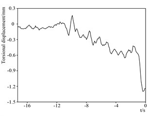
In Figs. 8-11, the end point of the curve is the moment when the projectile exits the muzzle. By analyzing the vibration displacement curve of the muzzle, it can be obtained that during the movement of the projectile, the vibration displacement of the artillery muzzle reaches the maximum at the muzzle exit time, which is 101 mm. The vibration displacement of the artillery muzzle in the up and down direction has always been negative, indicating that the muzzle has been moving downward from the start of the projectile, and the projectile reaches the maximum at the muzzle moment, about 1.5 mm. The vibration displacement curve of the artillery muzzle in the left and right direction indicates that the muzzle is always biased to the left, and the moment of the muzzle reaches the maximum, about 2.4 mm. The torsion displacement of the muzzle is also the largest at the moment when the projectile exits the muzzle, and it is counterclockwise, about 1.4 mm. The curve rule is consistent with the vibration law of the artillery muzzle.
Fig. 8Recoil displacement
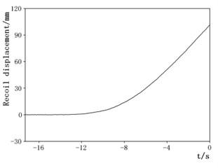
Fig. 9Movement displacement of the muzzle in the up and down direction
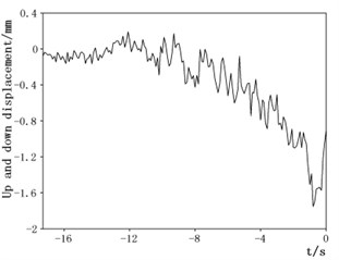
Fig. 10Displacement in the left and right direction
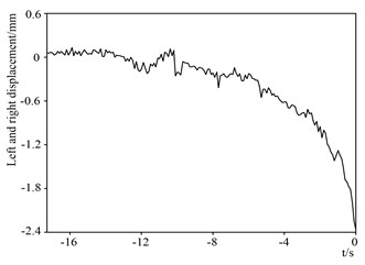
Fig. 11Muzzle torsional displacement
4. Measurement uncertainty analysis
Since the muzzle vibration displacement is directly measured by image processing, Therefore, the main component (class B evaluation) of the standard uncertainty of its single measurement (left and right muzzle vibration displacement) is:
(1) The maximum background noise of the displacement curve obtained after image processing is ±0.025 mm, normal distribution, then the uncertainty introduced by this term is: 0.025/2 = 0.0125 mm;
(2) Subpixel tracking error is 20 %, normal distribution, take the muzzle vibration to 0.8 mm, then the uncertainty introduced by this term is: 0.2 × 0.8 ÷ (2 × 2) = 0.04 mm;
(3) The maximum error of ruler is 0.5mm, uniform distribution, the ruler spacing is 120 mm, take the muzzle vibration to 0.8 mm, then the uncertainty introduced by this term is: 0.5 × 0.8 ÷ (120 × 2 × 31/2) = 0.001 mm;
(4) The error of the local deformation of the muzzle is estimated to be 0.02 mm, normal distribution, then the uncertainty introduced by this term is: 0.02 ÷ (2 × 2) = 0.005 mm;
(5) The image of the camera barrel at the back is not perpendicular to the x-axis, the maximum error is 0.02 mm, normal distribution, then the uncertainty introduced by this term is: 0.02 ÷ (2 × 2) = 0.005 mm;
(6) The maximum error of the marker point is 1 pixel (about 0.5 mm), resulting in a single mark point torsion measurement error of 0.05 mm, vibration displacement test error is 0.1 mm, normal distribution, then the uncertainty introduced by this term is: 0.1 ÷ (2 × 2) = 0.025 mm;
(7) The uncertainty introduced by high-speed camera calibration is 2.2 %, take the muzzle vibration to 0.8 mm, then the uncertainty introduced by this term is: 0.022 × 0.8 ÷ 2 = 0.0088 mm;
Then the total standard measurement uncertainty is: 0.05 mm, extended uncertainty is: take a confidence level of 95 %, 2, the resulting extended uncertainty is:
5. Conclusions
Through the application of vibration displacement measurement method of high elevation muzzle of large-caliber gun, the vibration displacement of the 155 mm gun at the front and rear, up and down and left and right sides of the artillery muzzle at 45° angle is obtained. The uncertainty of the measurement result is about 0.1 mm, and the measurement accuracy fully meets the requirements of the vibration displacement of the muzzle to the measurement system.
As a non-contact test method, it can eliminate the impact of the tube twist on the test results and obtain a more accurate three-dimensional displacement of the muzzle. The test system is not affected by the muzzle shock wave and the vibration of the artillery, and is fully applicable to the three-dimensional vibration displacement test of the large-caliber artillery muzzle. In the small vibration displacement test of weapons and equipment, the test method also has certain advantages and potentials.
References
-
Fang Yu, Qin Junqi, Di Changchun, et al. Research on modeling of a vehicle-mounted automatic mortar and muzzle vibration characteristics analysis. Fire Control and Command Control, Vol. 43, Issue 2, 2018, p. 118-121.
-
Wang Baoyuan, Shao Xiaojun Summarization of the measurement method for muzzle vibration responses. Journal of Gun Launch and Control, Vol. 9, 2010, p. 112-116.
-
Wang Baoyuan, Chen Shunde, Zhou Faming, et al. Experiment methods for gun vibration and launch dispersion. Journal of Gun Launch and Control, Vol. 4, 2010, p. 89-93.
-
Chen Yanhui, Guo Min, He Zongying, et al. Muzzle vibration test method and practice. Journal of Gun launch and Control, Vol. 3, 2010, p. 80-83.
-
Wang Baoyuan, Zhang Pengfei, Chao Hongxiao, et al. Study on measurement technique of muzzle vibration displacement with high-speed digital imaging method. Journal of Test and Measurement Technology, Vol. 28, Issue 5, 2014, p. 413-417.
-
Li Shili, Guo Min, et al. Measurement of tank gun muzzle vibration based on image processing with high sub-pixel precision. Journal of Test and Measurement Technology, Vol. 31, Issue 2, 2017, p. 45-50.
-
Zhao Gang Research on Measuring Method of Large-Caliber Gun Muzzle Vibration. Nanjing University, Nanjing, 2015, p. 50-62.
-
Wu Huimin, Song Chunxia, et al. The study on the characters of the dynamic response of the coupled system of projectile moving in the barrel under ideal state. Journal of Gun Launch and Control, Vol. 4, 2013, p. 92-96.
-
Wang Lili Foundation of Stress Wave. National Defense Industry Press, Beijing, 2005.
About this article

