Abstract
Achieving high firing accuracy of tank on the move is challenging. For improving firing accuracy, better understanding launching dynamic behavior of tank firing on the move is required. This study established a rigid-flexible coupling dynamic model of tank firing on the move. Thereinto, the barrel flexibility was considered based on the FFlex body technology, and the contact-impact algorithm was used to describe the projectile-barrel interaction. With the sinusoid superposition method, a three-dimensional road surface spectrum file considering the coherence of left and right tracks was created. Based on the results obtained in simulation, this study discussed the dynamic behaviors of a tank gun system such as the barrel curvature and the influence of projectile-barrel interaction on firing accuracy of tank firing on the move, in which the factors including projectile type, driving speed and road roughness were taken into consideration. The results indicated that the barrel curvature and the muzzle vibration do not increase simply with the increase of road roughness and driving speed as common sense.
1. Introduction
Firing accuracy of tank on the move is one of the primary objective to evaluate the tank performance. With the continuous improvement of modern tank for high mobility and high muzzle velocity, achieving high firing accuracy of tank firing on the move is challenging. For improving firing accuracy of tank on the move, better understanding launching dynamic behavior of tank gun system on the move is required.
Modern tank gun barrels are long, relatively thin, beam-like hollow cylinders. Their accuracy is influenced by their flexibility, especially under dynamic loading [1]. Very small deflections and rotations of the muzzle end can have a significant influence on the firing accuracy at long ranges. Muzzle motions induced by firing are inevitable, and difficult to control because the launching time scale is the order of milliseconds. Researchers have performed many experimental and numerical studies in order to investigate the effect of the longer gun barrel on the firing accuracy of the tank gun [2]. Bundy [3] described a method that can determine what combination of fundamental mode shapes is most likely to occur. Then, the effect of barrel flexure on gun accuracy could be understood and quantified. Ahmad [4] evaluated the maximum stress of the tank hull based on the finite element method. Gur [5] described a methodology for comparing two types of tank guns regarding their accuracy performances and dynamic behaviors. The findings indicated barrel curvature is the most dominant factor that governs jump error. In addition, for reducing the detrimental effect of the gun barrel vibration on the firing accuracy, Ismail and Peng [6, 7] presented approaches to control the non-linear vibration of barrel by a passive vibration absorber or using piezoelectric materials respectively. In these researches, the barrel non-linear vibration was mainly induced by the interaction with a high-speed moving projectile. However, the main source of vibration in a main battle tank is the running gear system. The ground-induced motion of hull transmitting through the trunnions and gun actuators can be large and has influence on the barrel vibration and firing accuracy. So, investigation on the barrel curvature of tank firing on the move in the paper is useful.
On the other hand, the barrel is a guide rail for the projectile. The motion of the projectile along the curved path of the barrel results in transverse reaction loads which drives the gun motion.
So, the influence of projectile-barrel interaction on firing accuracy of tank firing on the move is complex. Ding [8] proposed a meshing strategy to improve analysis accuracy with respect to the interaction between the worn barrel and the projectile. Liu [9] established the nonlinear dynamic model of the projectile-barrel interaction by considering elastic-plastic properties of the material and analyzed the impact between projectile and barrel. Gerasimov [10] presented approaches to reduce the transverse load on a projectile accelerating in the barrel of a light-gas gun. Researches in these papers and some others [11, 12] are gun launch process at static state. However, the interactions between the tracks and the ground will increase the computation complexity of the projectile-barrel interaction of tank firing on the move. So, it was ignored in most of these dynamic simulation studies [13, 14]. Liu [15] established a dynamic model of tank with flexible barrel, derived the launch dynamic equations and compiled the simulation program of launch dynamics. It was found that flexible barrel had a significant impact on the muzzle elevation angular displacement and the collision force between the projectile and barrel. However, the influences on the muzzle response of projectile type, driving speed and road roughness are not be took into account and need to be put forward further.
In this study, a rigid-flexible coupling dynamic model of tank firing on the move was established by using the FFlex body technology and contact-impact algorithm. Based on the results obtained in simulation, this study discussed the dynamic behaviors of a tank gun system such as the barrel curvature and the influence of projectile-barrel interaction on firing accuracy of tank firing on the move, in which the factors including projectile type, driving speed and road roughness were taken into consideration. The results indicated that the barrel curvature and the muzzle vibration do not increase simply with the increase of road roughness and driving speed as common sense.
2. Road model and tank dynamic model
2.1. Three-dimensional road roughness model
Road roughness represents the deviation degree of the road surface relative to the known ideal base plane. It is the main factor causing hull vibration of tank firing on the move. Therefore, the main point of the modeling is refactoring the road roughness accurately. According to the actual statistical characteristics, the road roughness signal is a stationary Gaussian process [16]. The statistical characteristics are usually given by power spectral density in frequency domain. The power spectral density of the road roughness can be fitted from the following formula [17]:
where is the space frequency. is reference space frequency. is the power spectral density of the reference space frequency and it is road roughness coefficient. is the exponential of frequency. The road roughness was divided into 8 classes by the power spectral density of the road roughness, and the geometric average of road roughness coefficient was shown in Table 1.
The harmonic superposition method was used to refactor the road roughness in the paper. The road roughness can be superimposed by a series of sinusoidal functions with random phases and it can be expressed as [16]:
where and are the variance and frequency of the th sine function component. is length in the road direction. is the evenly distributed random number in [0, 1].
Table 1The classification standard of road roughness
Road class | A | B | C | D | E | F | G | H | |
/(10-6 m3) ( 0.1 m-1) | Upper limit | 8 | 32 | 128 | 512 | 2048 | 8192 | 32768 | 131072 |
Geometric average | 16 | 64 | 256 | 1024 | 4096 | 16384 | 65536 | 262144 | |
Lower limit | 32 | 128 | 512 | 2048 | 8192 | 32768 | 131072 | 524288 | |
The road space frequency was divided into intervals and the corresponding power spectral density value of the central frequency of each interval was used to substitute for the value of the whole range approximately. So can be written as:
Then the 2-dimension random road roughness can be expressed as:
where is the amplitude of the harmonic fluctuation corresponding to the center frequency:
Considering the coherence of left and right tracks, a method [18] to numerically fitting the right wheel could be given:
where is the wheelbase. is the experience value. and are the lower and upper limit of the road space frequency respectively.
The random phase angle of the road roughness function is the main factor causing the difference of excitations between the left and right tracks. According to the Eq. (6), the phase angle coherence of the left and right tracks under road excitation was fitted in Ren et al. [19]:
where is the new generated random number in [0,1].
According to the above Eq. (4), by replacing with , the random road roughness of right track can be represented as:
By replacing with which is the length vertical to the road direction, the random process of the three-dimensional road can be represented as:
Fig. 1The road profile in 2-dimension plot
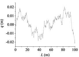
a) B class
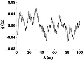
b) D class
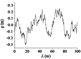
c) F class
According to the above equations, the three-dimensional road roughness model of the 100 m long and 5 m wide road was reconstructed. The code of road surface spectrum was compiled in MatLab. By using the node suture method, the file of the road surface that software RecurDyn can read was generated. At present, the vertical stabilization accuracy of tanks driving on a standard medium rough road with a moderate speed (20 km/h to 25 km/h) was used to evaluate the gun performance. The standard medium rough road is nearly between B and D class. So, B and D class road were used as excitation input to the dynamic model in the paper. The road profile in 2-dimension plot along the road length is shown in Fig. 1.
2.2. Dynamic modeling of tank firing on the move
In tank multibody dynamics model, it is important to include one or more flexible bodies in order to obtain accurate results. The modal method is the common method used in the rigid-flexible coupling dynamics of gun that can reduce a complex meshed finite element to a series of modes. However, model contact with the modal flexible body is not accurately because the associated static correction modes needed for accuracy are not available. FFlex body technology is a new method for working with flexible bodies proposed in RecurDyn [20]. It can define a flexible body by reading a finite element mesh using industry-standard file formats and represents a local deformation due to contact force accurately. Based on the FFlex body technology, the flexible barrel model was established. The barrel was discretized by isoparametric hexahedral elements with a total of 36960 elements and 52073 nodes. It was connected to the breech ring with the interface node. The sketch of the projectile-barrel interaction model is shown in Fig. 2. The contact force was calculated based on penalty function method and the formula [21] is:
where is contact stiffness coefficient, is damping coefficient, is the penetration depth and is the velocity at the contact point. , are the index of stiffness and damping respectively. is the index of notch, which produces the notch damping effect and can avoid the contact force being negative when the penetration is very small.
The contact frictional force can be represented as:
where is the friction coefficient determined by the relative tangential velocity of contact point and is the maximum frictional force.
Fig. 2A sketch of the rigid-flexible model for projectile-barrel interaction
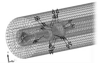
Fig. 3The multi-body system dynamic model of tank firing on the move
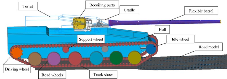
The tank mainly consisted of chassis and firepower part. They were connected with each other by turret race. The chassis consisted of hull, road wheels, support wheels, idle wheel, driving wheel and track shoes. The quality and inertia of other parts were converted to the hull through calculating. The firepower part mainly consisted of the recoiling parts, cradle parts and turret parts. The rotation relationship between cradle and turret was simulated by defining the contact between trunnion and bearing. The torsion spring was used to simulate the contact model of elevating gear and elevating gear arc. The contacts between the barrel and the bushing were defined. The contact force was calculated by user subroutine, which was inserted with application programming interface. Unless stated otherwise, the parts were connected with each other by joints. As shown in Fig. 3, the whole model contained 260 rigid bodies and an FFlex body. The whole system had 158550 degree of freedoms in total.
3. Numerical simulation and analysis
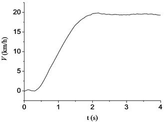
The driving speed of tank is shown in Fig. 4. The tank was at the accelerating stage during the time period of 0-2 s. After the tank reaching an even speed (at about 4 s), the gun barrel resulting force was exerted on the interface node on the aft end face of barrel and the base pressure was exerted on the bottom of the projectile by function to simulate the launch process. The recoil mechanism and recuperator forces were exerted directly on the appropriate location and computed through function, respectively.
Fig. 4The driving speed of tank
3.1. Analysis of barrel dynamic curvature
The barrel curvature data when launching armor piercing projectile were calculated. The length of barrel is 6.8 m and the in-bore time of armor piercing projectile is typically approximately 6.56 ms. 7 points (approximately one point per meter) on the barrel were chosen. The displacements of these points relative to the reference axis were used to describe the barrel curvature. The driving condition parameters are shown in Table 2.
Table 2The parameter settings of the driving conditions
Case | 1 | 2 | 3 | 4 | 5 | 6 |
Speed / (km/h) | 15 | 15 | 15 | 30 | 30 | 30 |
Road class | B | D | F | B | D | F |
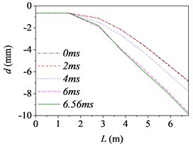
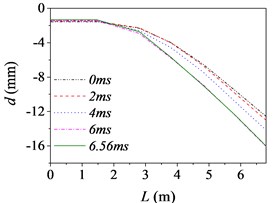
Fig. 5The barrel curvature state diagram
a) Case 1 (15 km/h, B)
b) Case 2 (15 km/h, D)
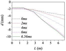
c) Case 3 (15 km/h, F)
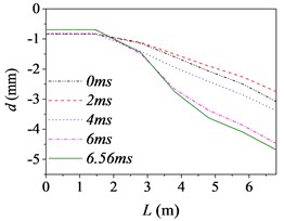
d) Case 4 (30 km/h, B)
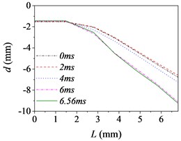
e) Case 5 (30 km/h, D)
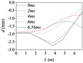
f) Case 6 (30 km/h, F)
Fig. 5 shows the barrel curvature states in the vertical direction at several different times, (approximately every 2 ms during launching) respectively. In Fig. 5(a)-(e), the motion is well developed along the entire barrel length and the barrel bends downward. It matches with common sense and verifies the correctness of the model indirectly. However, the motion in Fig. 5(f) is much more wavelike. That is, the barrel curvature is influenced by driving condition greatly, but it does not increase simply with the increase of road roughness and driving speed as common sense.
The barrel curvature of tank firing on the move consisted of two parts: the curvature for the gravity and the random vibration for the excitations stemming from the ground. When the speed of tank is slow, or the road condition is good, the gravity of barrel is the main cause of barrel curvature. So, the barrel bends downward in the majority of cases. At the same time, the excitations of tank stemming from the ground during driving will transmit to barrel and cause the motion of the barrel. So, the barrel curvature is different, though it bends downward in Fig. 5(a)-(e). The influence on barrel curvature caused by the excitations stemming from the ground has a trend of increase with the increase of road roughness and driving speed. If the driving speed of tank is fast or the road conditions is poor, the influence on barrel curvature caused by the excitations stemming from the ground may be the main cause of barrel curvature and even bigger than that caused by the gravity. So sometimes the barrel curvature is not severe, although tank firing on the move with a high speed and an uneven road, such as the 6th driving condition.
Moreover, the barrel curvature decreases with the increase of the speed of tank in Fig. 5. The changes of the barrel curvature are unordered with the decrease of road roughness. So, we can draw a conclusion that the barrel curvature is more sensitive to the driving speed than road roughness. The difference is also especially obvious in comparing the time histories of the barrel shapes. Through comparing, we can find that the barrel curvature increased with time on the overall trend, because of the increasing of action time.
To sum up, the barrel curvature of tank firing on the move is combined by the curvature for the gravity and the random vibration for the excitations stemming from the ground. Therein, the influence on barrel curvature caused by the excitations stemming from the ground has a trend of increase with the increase of road roughness and driving speed. So, the barrel curvature should be included in any theory of gun barrel motion during firing. When correcting the error of firing accuracy, the barrel curvature state should be measured in real time to ensure the accuracy of the correction.
3.2. Analysis of projectile-barrel interaction
The projectile-barrel interaction influences the trajectory of projecti1e and the muzzle vibration of tank firing on the move. In order to analyze the muzzle vibration influenced by projectile type, the muzzle responses with two different projectiles were calculated, respectively. The road class was D and the driving speed was 20 km/h. The two different projectiles considered in the paper were armor piercing projectile and high explosive projectile. The trial calculation results show that the muzzle responses were different at the initial moment when launching different types of projectiles. In order to eliminate the differences and facilitate comparative analysis, a certain boundary condition needed to be set. In the paper, all the projectiles were loaded in the bore at the initial time of calculation. At the beginning of launch, the simulation script control command was used to disable the unrelated contact force. Then, the differences of muzzle responses at the initial moment when launching different types of projectiles were eliminated successfully.
Fig. 6The muzzle elevation angular velocity
a) The armor piercing projectile
b) The high explosive projectile
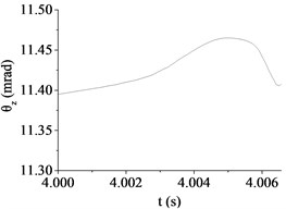
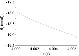
Fig. 7The muzzle elevation angular displacement
a) The armor piercing projectile
b) The high explosive projectile
Fig. 6, 7 show a comparison in the muzzle elevation angular displacement and angular velocity of tank firing on the move. The figures show that after considering the projectile-barrel coupling problem, the muzzle responses are significantly different. The vertical muzzle angular velocities are both increased at the time of the projectile passing muzzle when shooting armor piercing projectile or high explosive projectile. It is easy to find that the muzzle angular displacement and velocity curves are almost overlap within the first half of process that the projectile moving through the bore. With the increase of the projectile velocity, the collision between projectile and barrel wall becomes more intense and the distance between projectile and muzzle becomes short. The influences on the muzzle response of the projectile-barrel coupling become large, so the vertical muzzle angular velocity increases obviously after considering the projectile-barrel coupling problem. Obviously, it is beneficial to the calculation accuracy of the muzzle response after considering the projectile-barrel interaction.
Comparing to the armor piercing projectile, the high explosive projectile has a relatively long in-bore time, approximately 13.4 ms. From Fig. 6(a), (b), it is clear that the high explosive projectile exhibits a more violent dynamic path than the armor piercing projectile, which causes a relatively big angular velocity of muzzle when launching high explosive projectile. This is because when comparing with the armor-piercing projectile, the weight and base pressure of the high explosive projectile are both greater. From Fig. 7(a), (b), since the high explosive projectile is relatively heavy and stiff, the muzzle elevation angular displacement would be expected to be very different from the valve of armor piercing projectile. Though the initial conditions are same, the angular displacement at muzzle-exit are different.
Table 3The absolute value of muzzle elevation angular displacement at muzzle-exit
Projectile type | Armor piercing projectile | High explosive projectile | ||
Projectile-barrel interaction | No | Yes | No | Yes |
(mrad) | 11.37 | 11.41 | 13.50 | 13.75 |
As shown in Table 3, the absolute value of muzzle elevation angular displacement at muzzle-exit is 13.75 mrad when launching the high explosive projectile. However, the value is only 11.41 mrad when launching the armor piercing projectile. The latter reduces 17.02 % than the former, mainly because the high explosive projectile has a relatively long in-bore time than the armor piercing projectile. Obviously, the projectile types have great influence on the muzzle vibration and the firing accuracy of tank firing on the move. When correcting the error of firing accuracy, the projectile type should be taken into consideration.
3.3. Analysis of driving condition
The muzzle responses of tank firing on the move will also be influenced by driving speed and road roughness. In the paper, the dynamic muzzle responses with different driving conditions were calculated respectively when launching armor piercing projectile. Fig. 8 shows the comparison in the muzzle elevation angular displacement of tank firing on the move. The driving condition parameters are shown in Table 4.
Table 4The parameter settings of the driving conditions
Case | 1 | 2 | 3 | 4 | 5 | 6 |
Speed (km/h) | 10 | 20 | 30 | 10 | 20 | 30 |
Road class | B | B | B | D | D | D |
Because the excitations of hull stemming from the ground is random, the muzzle conditions when launching projectiles are different. The initial angular displacements are unordered with the change of driving speed or road roughness in Fig. 8. Through comparing, with the increase of road roughness and driving speed, the change of muzzle elevation angular displacement during projectile moving in bore has a trend of increase. That is, the influence on muzzle vibration will increase with the increase of road roughness and driving speed. It is because the hull stability decreases and the contact between barrel and bushing becomes more violent. However, because of the difference of the initial muzzle conditions when launching projectiles and the randomness of hull vibration caused by road roughness, the influence on the absolute value of muzzle elevation angular displacement at muzzle-exit is not obvious. As shown in Table 5, the absolute value of muzzle elevation angular displacement at muzzle-exit increases with the increase of road roughness. However, the value is uncertain with the increase of driving speed. So, we can draw a conclusion that the absolute value of muzzle elevation angular displacement at muzzle-exit is more sensitive to the road roughness than driving speed.
Fig. 8The muzzle elevation angular displacement
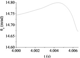
a) Case 1 (10 km/h, B)
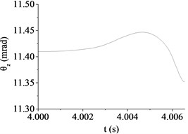
b) Case 2 (20 km/h, B)
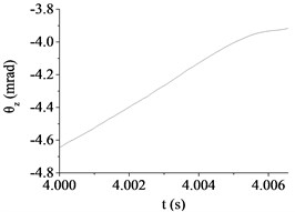
c) Case 3 (30 km/h, B)
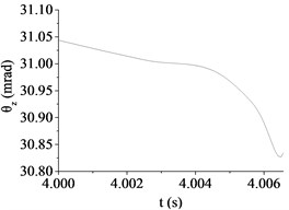
d) Case 4 (10 km/h, D)
e) Case 5 (20 km/h, D)
f) Case 6 (30 km/h, D)
Table 5The absolute value of muzzle elevation angular displacement at muzzle-exit
Road class | B | D | ||||
Speed (km/h) | 10 | 20 | 30 | 10 | 20 | 30 |
(mrad) | 14.67 | 11.35 | 3.92 | 30.84 | 11.41 | 19.15 |
Obviously, the influences of driving speed and road roughness increase the difficulty about improving firing accuracy of tank firing on the move. The fact that the muzzle response is mainly caused by the excitations stemming from the ground which leads to the hull stability deteriorated. Therefore, the research of improving hull stability is beneficial to improve the firing accuracy of tank firing on the move. Moreover, in order to ensure the firing accuracy, it is necessary to select a flat road and low driving speed in the process of actual firing. However, due to the randomness of ground excitation, the rules of influence caused by road roughness and driving speed are not obvious and it is difficult to forecast the muzzle response. So, it had better measure the muzzle response in real-time with the help of synchronized sensor when correcting firing error.
4. Conclusions
A more accuracy dynamic model of tank firing on the move was established in the paper. The flexibility of barrel and the projectile-barrel interaction were considered based on the FFlex body technology and contact-impact algorithm respectively. With the sinusoid superposition method, the three-dimensional road model was reconstructed. The dynamic behavior of tank firing on the move was analyzed in the paper and the main conclusions are as follows:
1) The influence on barrel curvature caused by the excitations stemming from the ground has a trend of increase with the increase of road roughness and driving speed. But the barrel curvature does not increase simply with the increase of road roughness and driving speed as common sense. Obviously, the barrel curvature should be included in any theory of gun barrel motion during firing and the established dynamic model with flexible barrel is more accuracy.
2) It is beneficial to the calculation accuracy of the muzzle response when considering the projectile-barrel interaction. Projectile type has a significant influence on the muzzle response. The high explosive projectile exhibits a more violent dynamic path than the armor piercing projectile. When launching high explosive projectile, the muzzle vibration is relatively bigger than launching armor piercing projectile.
3) The driving conditions also has a significant influence on the muzzle response. The muzzle vibration is mainly caused by the excitation from the ground. The influence on muzzle vibration has a trend of increase with the increase of road roughness and driving speed. But the relationship between the absolute value of muzzle elevation angular displacement at muzzle-exit and driving condition is not certain because of the difference of the initial muzzle conditions when launching projectiles.
This study investigated factors influencing the firing accuracy of tank firing on the move. However, the paper only has a preliminary investigation and it is necessary to verify the established model with more test values. In addition, the stabilizer system was ignored, and it is the focus of the follow-up study.
References
-
Sneck Henry J. Main Battle Tank flexible gun tube disturbance model three segment model. Proceedings of the Tenth US Army Gun Dynamics Symposium, Austin, Texas, 2001, p. 99-106.
-
Dursun T., Büyükcivelek F., Çağrıhan Utlu A review on the gun barrel vibrations and control for a main battle tank. Defence Technology, Vol. 13, 2017, p. 353-359.
-
Bundy M., Newill J., Marcopoli V., et al. A methodology for characterizing gun barrel flexure due to vehicle motion. Shock and Vibration, Vol. 8, Issues 3-4, 2001, p. 223-228.
-
Ahmad S., Kumar V. Structural integrity analysis of a battle tank gun barrel during service. Defence Science Journal, Vol. 65, Issue 1, 2015, p. 83-89.
-
Gur Y., Azulay I., Touati D., et al. Jump error and gun dynamics: a comparison between two types of 120mm smooth-bore tank guns. 23th International Symposium on Ballistics Tarragona, 2007, p. 565-572.
-
İsmail Esen, Koç M. A. Optimization of a passive vibration absorber for a barrel using the genetic algorithm. Expert Systems with Applications, Vol. 42, Issue 2, 2015, p. 894-905.
-
Peng F. S., Ning W., Shu L. S., et al. Study on vibration control of gun tube with intelligent structure. Applied Mechanics and Materials, Vol. 757, 2015, p. 165-169.
-
Ding Chuanjun, Liu Ning, Zhang Xiangyan A mesh generation method for worn gun barrel and its application in projectile-barrel interaction analysis. Finite Elements in Analysis and Design, Vol. 124, 2017, p. 22-32.
-
Liu Jun, Shao Xiaojun, Zeng Zhiyin, et al. The analysis of impact between projectile and barrel in bore. Journal of Gun Launch and Control, Vol. 39, Issue 2, 2018, p. 33-37, (in Chinese).
-
Gerasimov S. I., Erofeev V. I., Kamchatyi V. G., et al. Transverse motion of a projectile in the barrel of a light-gas gun. Russian Engineering Research, Vol. 38, Issue 2, 2018, p. 80-85.
-
Zhou Qizheng, Zhao Yang, Wang Deshi Transverse vibration characteristics of barrels subjected to accelerated moving projectiles during the artillery continuous firing. Journal of Vibration and Shock, Vol. 37, Issue 6, 2018, p. 99-103, (in Chinese).
-
Alexander J. E. Advanced gun system gun and projectile dynamic model results and correlation to test data. Journal of Pressure Vessel Technology, Vol. 134, Issue 4, 2012, p. 669-679.
-
Xie Run, Yang Guolai Dynamic analysis for self-propelled gun on the move with backlash nonlinearity between gear and arc. International Forum on Special Equipments and Engineering Mechanics, Nanjing, 2013.
-
Chen Yu, Yang Guolai Dynamic simulation of tank stabilizer based on adaptive control. Proceedings of the Institution of Mechanical Engineers, Part C: Journal of Mechanical Engineering Science, 2018, https://doi.org/10.1177/0954406218802315.
-
Liu Feifei, Rui Xiaoting, Yu Hailong, et al. Study on launch dynamics of the tank marching fire. Journal of Shanghai Jiaotong University, Vol. 21, Issue 4, 2016, p. 443-449.
-
Wang Hongyan, Wang Qinlong, Rui Qiang, et al. Research on digitized modeling method of riding road of vehicle. Acta Armamentarii, Vol. 37, Issue 7, 2016, p. 1153-1160, (in Chinese).
-
Eiyo F. Effect of Off-Road Surface Roughness on Tyre Performance. Dissertation of Doctor of Philosophy, Montreal, 1989.
-
Bogsjo K. Coherence of road roughness in left and right wheel-path. Vehicle System Dynamic, Vol. 46, Issue 1, 2008, p. 599-609.
-
Ren Hongbin, Chen Sizhong, Wu Zhicheng, et al. Time domain excitation model of random road profile for left and right wheels. Transactions of Beijing Institute of Technology, Vol. 33, Issue 3, 2013, p. 257-259, 306, (in Chinese).
-
Kim S. W. Evaluation of structural deformations of a mechanical connecting unit for oxidizer supplies by thermo-mechanical simulation. Journal of Mechanical Science and Technology, Vol. 30, Issue 10, 2016, p. 4669-4677.
-
Chen Shiye, Pan Yuzhu, Wang Lanzhi, et al. Dynamic optimization design of a projectile-barrel rigid-flexible coupled system based on virtual substance technology. Journal of Vibration and Shock, Vol. 35, Issue 5, 2016, p. 153-158, (in Chinese).
Cited by
About this article

