Abstract
A mechanism of fluid bag shock absorber which could provide axial shock protection under small displacement and small deformation was designed. The finite element model of the mechanism was established in ABAQUS, the different types of loads imposed on the bottom of mechanism when the mechanism worked in different environment were described and the load stiffness matrix was obtained when pressure loads were imposed on the mechanism. The effects of the notch in fluid bag on axial stiffness characteristics were discussed. The results indicate that the flip of inner shell occurs as the axial concentrated load is imposed to the bottom of inner shell and the notch in fluid bag has little effects on the increment of pressure and volume variation of bag. The equivalent axial force generated by pressure loads imposed on the inner shell was calculated, the axial displacement of inner shell as well as increment of bag pressure caused by pressure loads is larger than concentrated load. The effects of different factors affecting the axial stiffness characteristics were discussed. The factor of load type has almost no effects on the axial stiffness variation, and has small impact on the increment of pressure variation of bag; Outer shell appears to be one of the crucial factors affecting the axial stiffness and increment of bag pressure variations; Fluid bag is the key factor determining the axial stiffness characteristics of mechanism, both of the axial displacement of inner shell and increment of bag pressure increase with loads when the pressure loads are imposed on the surface of fluid bag.
1. Introduction
As the increasing requirement of security and reliability of mechanical equipment, different kinds of shock absorbers have been designed to prevent the equipment from rigid collision due to impact load, reduce the vibration and noise, improve the equipment’ s quality and lifespan. Currently there have been a lot of researches about the shock absorbers, such as air springs and hydraulic buffers. Air springs contribute deeply to the improvement of ride comfort and have been widely used in vehicle suspensions and cabin seats [1, 2]. The research proposed by Pak Kin W. studied some alternative factors on the characteristics of the rolling lobe air spring, a numerical model of air spring was built and numerical results show that the newly proposed model is reliable to determine the vertical characteristic and physical dimensions of the rolling lobe air spring [3]. Ziyue Wang and others studied using minimal order observer instead of the pressure sensor to control an air spring type anti-vibration apparatus [4]. Hydraulic buffers have been widely applied in railway vehicle suspension systems for their excellent performance in terms of large capacity and smooth cushioning properties. Some researches focus on the simulation of hydraulic buffer device to study the influencing factors and dynamic characteristics of hydraulic buffer [5-7]. The research proposed by Chen Qiping studied a fluid structure interaction method to analyze the dynamics characteristic between circulation valve and liquid of hydraulic shock absorber, which provides a theoretical foundation for optimizing hydraulic shock absorber in the future [8]. However, since the cost of the air spring is high, hydraulic buffers generally have complicated structure and they cannot generate large loads under small displacement and deformation, thus both of them have their own limitations in practical applications.
Traditional shock absorbers are not suitable for the situation where shock protection is achieved by small displacement and small deformation. Therefore, a new fluid bag which acts as a shock absorber in a mechanism to provide axial shock protection under small displacement and deformation has been developed. The structure of fluid bag is similar to air spring, since the fluid bag is filled with the approximate incompressibility of fluid rather than the compressible gas, thus it can provide axial protection by small displacement and small deformation under large load. The factors affecting the axial stiffness of fluid bag and the performance of axial protection for the mechanism under an axial concentrated load have been discussed. The fluid bag was modeled integrally as ring shape for the convenience of investigating the factors affecting the axial stiffness [9]. As a matter of fact, there is a notch existing in the hoop direction of fluid bag, and there appears a lack of discussion on the notch in fluid bag. Investigation on the effects of the notch in fluid bag on the axial stiffness characteristics of mechanism is therefore of interest. Furthermore, since the mechanism of fluid bag shock absorber works in different environment, different types of loads are imposed on the bottom of mechanism respectively, but there appears lack of discussion on the axial stiffness characteristics of mechanism subjected to different types of loads. The purpose is to investigate the effects of different factors affecting the axial stiffness characteristics of mechanism.
This paper presents a study on the axial stiffness characteristics of a mechanism of fluid bag shock absorber subjected to different types of loads. This is done through several numerical models using Finite Element Method. The equivalent axial force generated by pressure loads imposed on the inner shell has been calculated, and a load corresponding principle has been carried out for the convenience to compare the simulation results of mechanism under different types of loads. This study focuses on the effect of the notch in fluid bag and different factors on the axial stiffness characteristics of mechanism.
2. Introduction of a mechanism of fluid bag shock absorber
2.1. The application of rubber joint
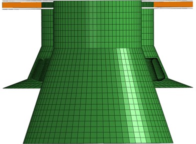
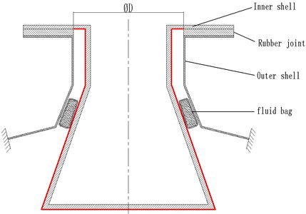
The mechanism of shock absorber is mainly comprised of two parts, one of the parts is rubber joint, and the other part is fluid bag. The diagram of a mechanism is shown in Fig. 1; large axial upward shock loads are imposed on the bottom of mechanism when the mechanism works.
Fig. 1The diagram of mechanism model
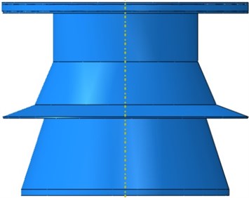
Fig. 2The diagram of rubber joint model
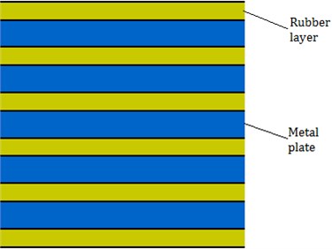
The rubber joint is a laminated rubber-metal spring [10-13], the metal plates and the rubber layers are glued together, large axial static displacement is not allowed otherwise failure may occur in the rubber joint, which resulting in the mechanism fail to work. So it is essential to use a shock absorber with large stiffness for axial protection of the rubber joint. Because the rubber joint is not the focus of analysis, to remain in line with the leading objective of this paper, further complexities associated with truly understanding and modeling the interface phenomenon between rubber and steel in detail were avoided. Instead, an absolute bonding between the rubber and steel plate was assumed [14], the diagram of rubber joint is shown in Fig. 2.
2.2. The application of fluid bag
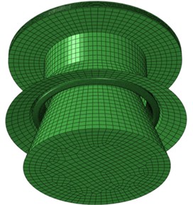
The diagram of fluid bag is shown in Fig. 3; it is a kind of taper ring flexibly sealed container which is filled fully with the approximate incompressible fluid. The real fluid bag does not link up in the hoop direction, there are closed rings on the head and tail ends of fluid bag which are used to be inserted by a hinge pin so as to lock the fluid bag in the mechanism, which also results in a notch existing in the hoop direction of fluid bag. A pressurized tube is connected to a connector and the bottom of fluid bag to achieve charging and pressurizing the fluid bag, the connector is connected to a pressurized liquid charging device at the same time.
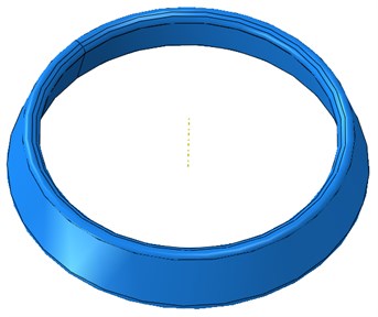
The pressure of fluid bag can be adjusted to the predetermined value, and fluid bag is placed between the inner and outer shell in the mechanism [9], which is able to largely decrease the loads transmitted to the rubber joint by large contact area with the inner and outer shell, the simplified model of fluid bag is shown in Fig. 4.
Fig. 3The diagram of fluid bag
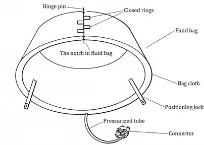
Fig. 4The simplified model of fluid bag
3. The establishment of mechanism of fluid bag shock absorber finite element analysis model
3.1. The finite element model of mechanism
From the research proposed by Ming Zhang, it is found that the curves of axial stiffness and pressure variations have good linearity in experiment results [9]. The linear static analysis method was adopted and the linear finite element models were built and analyzed, the results show that the difference between the simulation and experiment results is small, which demonstrates that the simulations hold water. The mechanism is under small deformation when subjected to working loads, linearity can be observed in the mechanical characteristics of mechanism. Thus it is feasible to adopt the linear formulation of FEM to analyze the mechanism of fluid bag shock absorber.
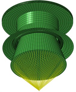
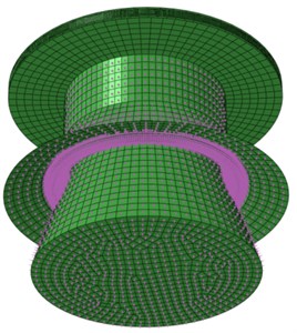
Due to the structure characteristics of mechanism of fluid bag shock absorber, the four node-shell element (S4R in the finite element analysis software-ABAQUS) was used to define the finite element model of bag, inner and outer shell, the eight node-solid element (C3D8 in ABAQUS) was used to define the rubber joint. Suppose during the flow process of fluid in fluid bag, both of the mass and temperature of fluid in bag remain constant. In this study, a three dimension-four node element (F3D4 in ABAQUS) which could be regarded as a volume element was adopted to represent the fluid element, the fluid element shared the same nodes but different element labels with the bag element so as to simulate the coupling between the bag and fluid. A reference node was set for all the fluid elements, and the density, temperature and pressure of fluid in bag were defined with the reference node [9, 15]. Thus the finite element model of mechanism of fluid bag shock absorber was completed, as is shown in Fig. 5.
Fig. 5The finite element model of mechanism
3.2. The simulation of contact
When the fluid bag is compressed, the contact states among inner, outer shell and fluid bag change with its deformation, which rules out the possibility of stress concentration in contact regions. In ABAQUS, this kind of contact is treated as finite-sliding interaction between deformable bodies, where separation and sliding of finite amplitude and arbitrary rotation of the surfaces may arise. Defining possible contact conditions by identifying and pairing potential contact surfaces, the appropriate contact elements are generated automatically. To define a sliding interface between two surfaces, one of the surfaces (the “slave” surface) is covered with ISL elements. The other surface (the “master” surface) is defined as a slide line surface composed of a series of nodes ordered in sequence [16]. Two contact pairs were defined in the paper. The first contact pair, the outer surface of inner shell being the master surface and inner diameter surface of bag being the slave surface, is shown in Fig. 6. The second contact pair, the outer surface of inner shell being the master surface and inner diameter surface of bag being the slave surface, is shown in Fig. 7 [9].
Fig. 6The master surface and slave surface for first contact pair
3.3. The boundary conditions and material properties
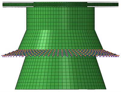
The outer shell of mechanism was fixed to the foundation, a load distributing coupling was set up between a reference node and the bottom surface of inner shell in order to avoid stress concentration when an axial concentrated load is imposed on the bottom of inner shell [9]. The diagram of boundary conditions and load distributing coupling is shown in Fig. 8.
Fig. 7The master surface and slave surface for second contact pair
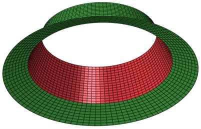
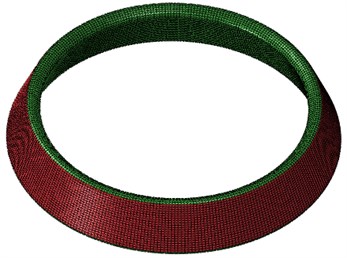
Fig. 8The diagram of boundary conditions and load distributing coupling
The material of steel plate, inner and outer shell is high-strength steel and the bag which filled fully with water is made up of rubber fiber. Suppose the temperature of water is 20 °C, the equivalent material properties are given in Table 1.
Table 1The material properties of model
Material | Density (kN/mm3) | Elastic modulus (MPa) | Possion’s ratio | Bulk modulus (MPa) | Temperature (°C) |
High-strength steel | 7.8×10⁻⁹ | 2.1×10⁵ | 0.3 | ||
Rubber fiber | 1.4×10⁻⁹ | 7.0×10³ | 0.3 | ||
Water | 1.0×10⁻⁹ | 2200 | 20 |
3.4. Introduction of load cases
Since the mechanism of fluid bag shock absorber works in different environment, different types of loads are imposed on the bottom of mechanism respectively.
When a concentrated load is imposed on the bottom of inner shell, the load is imposed to the load coupling reference node in the model, making the load distribute on the bottom surface of inner shell. The bottom of inner shell subjected to a concentrated load is defined as load case one, the diagram of load case one is shown in Fig. 9.
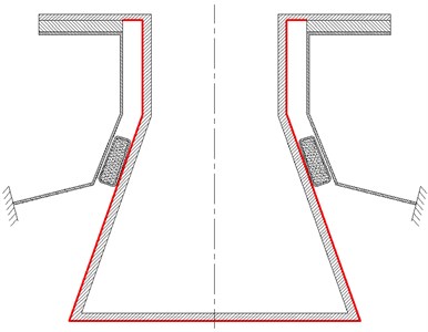
When pressure loads generated by pressurized gas act on the bottom of mechanism, the regions of outer surface of fluid bag, inner and outer shell exposed to gas are all subjected to pressure loads. Pressure load is a kind of uniformly distributed load, and the bottom of mechanism subjected to pressure loads is defined as load case two, the diagram of load case two is shown in Fig. 10.
Under the circumstances of load case two, pressure loads are applied on the deformed structure in geometrically nonlinear analysis. Hence, the equivalent nodal loads are dependent on the nodal displacements. This dependency leads to additional contributions to the Jacobian in the solution procedure. The external virtual work is given as:
where is the surface on which the pressure is applied; is the normal to this surface, pointing into the material; is the virtual displacement field; and is the pressure magnitude.
Fig. 9The diagram of load case one
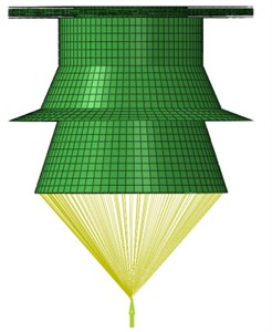
Fig. 10The diagram of load case two
When pressure loads are applied to solid elements used for the rubber joint, which means pressure loads act on the surface in three-dimensional space. Then the expression in Eq. (1) can be rewritten as follows:
where are the current coordinates of a point on the surface, and the surface parametric coordinates are chosen to give the correct sign to through the cross product. The external virtual work is then given by:
and the load stiffness matrix is obtained from:
where, for a solid, .
When pressure loads are applied to shell elements used for the bag, the inner and outer shell, which means pressure loads act on the surface in two-dimensional space. Then the expression in Eq. (1) can be rewritten as follows:
where is a unit vector out of the plane of the model, is the thickness of the two-dimensional solid (which is assumed to be constant), and the surface parametric coordinate is chosen to give the correct sign to through the cross product. The external work is then given by:
and the load stiffness matrix is obtained from the equation:
Thus pressure load stiffness on the surface in three- and two-dimensional space can be obtained [16].
4. The notch in fluid bag affecting the axial stiffness characteristics of mechanism
4.1. The simulation results of mechanism under load case one without the notch in fluid bag
Fluid bag was placed between the inner and outer shell in the mechanism, the bag got filled with fluid: the bag pressure being set to , the pressure was calculated when the fluid bag was in balance. If had not reached the predetermined initial working pressure, would be adjusted until met it [9]. After reaching the predetermined initial working pressure, the loads were imposed on the bottom of mechanism, analyzing the axial stiffness characteristics of mechanism.
When the initial working pressure is set to 2.5 MPa, the fluid bag swells compared to initial state, which results in pushing the inner shell downward. Suppose the initial position of inner shell was its original position, moving upward was defined as positive displacement. Then when the initial working pressure was set to 2.5 MPa and the mechanism worked without the notch in fluid bag, the axial displacement of inner shell was adjusted to –0.987 mm. After reaching the predetermined initial working pressure, the axial stiffness characteristics of mechanism under load case one was analyzed, the results are shown in Fig. 11, Fig. 12 and Fig. 13.
Fig. 11The diagram of axial displacement of inner shell and load case one
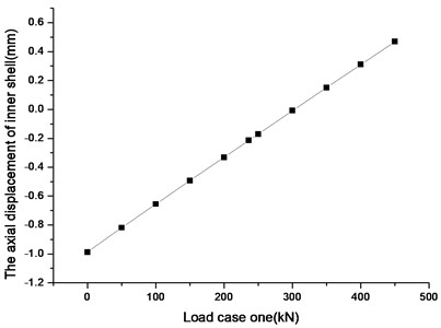
Fig. 12The diagram of increment of bag pressure and load case one
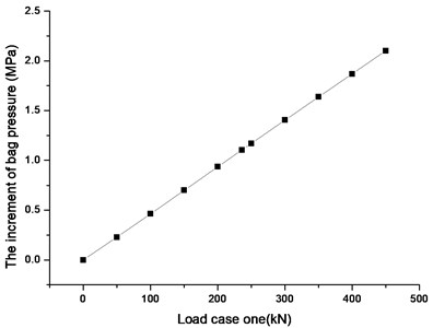
According to Fig. 11 to Fig. 13, as the increasing axial concentrated load is applied to the bottom of inner shell, the curves of axial stiffness, pressure and bag volume variations have good linearity.
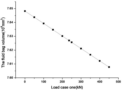
Fig. 13The diagram of bag volume and load case one
4.2. The simulation results of mechanism under load case one with the notch in fluid bag
According to Section 2.2, the real fluid bag does not link up in the hoop direction, but connecting head to tail by inserting a hinge pin into several closed rings, which results in a notch in the hoop direction of fluid bag. In order to analyze the effect of the notch in fluid bag on the axial stiffness of mechanism, a simplified fluid bag model with notch established is shown in Fig. 14. The eight node-solid element (C3D8R in ABAQUS) was used to define the part in notch which impedes fluid bag link up in the hoop direction, the other part of fluid bag with notch as well as material properties was consistent with that of the fluid bag without notch.
Fig. 14The diagram of simplified fluid bag model with notch
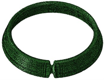
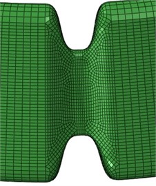
Fig. 15The diagram of four representative points on the inner shell
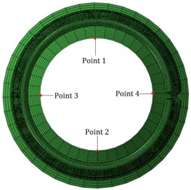
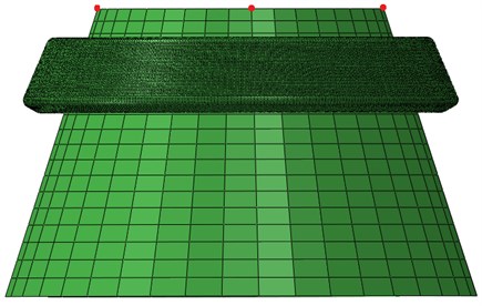
Due to the existence of notch in fluid bag, with the increasing axial concentrated load applied to the bottom of inner shell, lateral deviation and flip may occur in the inner shell. Thus four representative points on the inner shell were chosen as the axial displacement reference points, as is shown in Fig. 15.
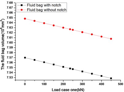
After setting the initial working pressure to 2.5 MPa, load case one was imposed on the bottom of inner shell to analyze the axial stiffness characteristics of mechanism, the results are shown in Fig. 16, Fig. 17, and Fig. 18.
Fig. 16The diagram of axial displacement of inner shell and load case one
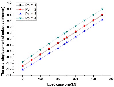
Fig. 17The diagram of increment of bag pressure and load case one
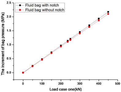
Fig. 18The diagram of bag volume and load case one
According to Fig. 16, the axial displacement of different reference points increases linearly with load, and the axial stiffness variation tendency of different reference points is almost the same. Due to the existence of notch in fluid bag, the inner shell turns around the centerline towards notch in fluid bag as the increasing axial concentrated load is imposed on the bottom of inner shell, which results in the considerable displacement difference between point 4 and point 3, that is because the axial displacement of point 4 equals to the axial displacement of inner shell plus the axial displacement generated by the flip of inner shell, and the axial displacement of point 3 equals to the axial displacement of inner shell minus the axial displacement generated by the flip of inner shell. The axial displacement curves of point 1 and point 2 draw near since they represent the axial displacement of inner shell.
According to Fig. 17, the curve of increment of bag pressure in fluid bag with notch almost coincide with that of increment of bag pressure in fluid bag without notch, indicating that the notch in fluid bag basically has no effects on the increment of bag pressure variation.
According to Fig. 18, since the bag volume of fluid bag with notch is smaller than that of fluid bag without notch when fluid bag is set to the same initial working pressure, it is found that the trend of curve of bag volume in fluid bag with notch is almost the same as that of bag volume in fluid bag without notch and both of curves have good linearity, which indicate that the notch in fluid bag basically has no effects on the bag volume variation.
5. The comparison of simulation results of mechanism under different load cases without the notch in fluid bag
5.1. The equivalent axial force of pressure loads acting on the surface of inner shell
The schematic diagram of mechanism of fluid bag shock absorber model is shown in Fig. 19, the red bold lines represent the regions subjected to pressure loads.
Fig. 19The schematic diagram of mechanism of fluid bag shock absorber model
When pressure loads generated by pressurized gas act on the bottom of mechanism, the regions of outer surface of fluid bag, inner and outer shell exposed to gas are all subjected to pressure loads. Suppose the pressure loads are only imposed on the surface of inner shell as is shown in Fig. 19, then the equivalent axial force generated by pressure loads can be calculated as follows:
where is the diameter described in Fig. 19, is the magnitude of pressure loads, and means the equivalent axial force generated by pressure loads.
Table 2A list of concentrated loads corresponding to pressure loads
Concentrated loads (kN) | Pressure loads (MPa) | Concentrated loads (kN) | Pressure loads (MPa) |
0 | 0 | 250 | 1.05932 |
50 | 0.21186 | 300 | 1.27119 |
100 | 0.42373 | 350 | 1.48305 |
150 | 0.6356 | 400 | 1.6949 |
200 | 0.84746 | 450 | 1.90678 |
236 | 1.0 |
Since the concentrated load is just imposed on the bottom of inner shell, the pressure loads act on much more regions than the concentrated load. Considering the structure characteristics of mechanism, a corresponding principle was carried out to compare the simulation results of mechanism under different load cases, which also helps figure out the effect of pressure loads act on different parts of mechanism on the axial stiffness characteristics in contrast to the concentrated load. The corresponding principle is if the value of concentrated load imposed on the bottom of inner shell in load case one equals to the equivalent axial force generated by pressure loads acting on the surface of inner shell, then it is considered that the concentrated load in load case one is corresponding equivalently to the pressure loads in load case two. Since the diameter described in Fig. 19 actually is 548.1 mm, if the magnitude of pressure loads is 1.0 MPa, with the help of Eq. (8), then equals to 236 kN, thus a list of concentrated loads corresponding to pressure loads is shown in Table 2.
5.2. The comparison of simulation results of mechanism under different load cases without the notch in fluid bag
As is mentioned in Section 4.1, the fluid bag without notch was placed between the inner and outer shell in the mechanism, when initial working pressure was set to 2.5 MPa, the axial displacement of inner shell was adjusted to –0.987 mm. After reaching the predetermined initial working pressure, the axial stiffness characteristics of mechanism under load case two has been analyzed, the results are shown in Fig. 20 and Fig. 21.
Fig. 20The diagram of axial displacement of inner shell and load case two
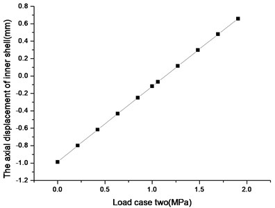
Fig. 21The diagram of increment of bag pressure and load case two
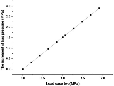
Fig. 22The diagram of axial displacement of inner shell and axial load
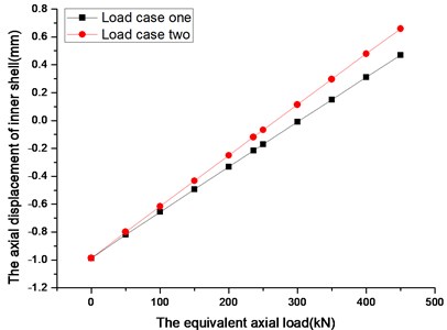
Fig. 23The diagram of increment of bag pressure and axial load
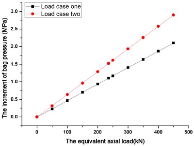
According to Fig. 20 and Fig. 21, the curves of axial stiffness and increment of bag pressure variations have good linearity as the increasing pressure loads are imposed on the bottom of mechanism.
According to Section 5.1, a load corresponding principle is carried out and the concentrated loads in load case one corresponding to the pressure loads in load case two are listed in Table 2. Comparing the simulation results of mechanism under load case one obtained in Section 4.1 with those of mechanism under load case two, plotted by the value of equivalent axial force on the horizontal axis, as is shown in Fig. 22 and Fig. 23.
In Fig. 22 and Fig. 23, the curves of axial stiffness and increment of bag pressure variations caused by load case two is larger than the corresponding curves caused by load case one, which indicates that the axial displacement of inner shell as well as increment of bag pressure caused by pressure loads is larger than concentrated load.
6. The factors resulting in the different simulation results of mechanism under different load cases
6.1. The factor of load type affecting the axial stiffness characteristics of mechanism
According to the load corresponding principle mentioned in Section 5.1, the concentrated loads in load case one equal to the equivalent axial force generated by pressure loads imposed on the surface of inner shell. Though the same effects of axial forces generated by different types of loads were imposed respectively on the bottom of inner shell, it was still unknown whether the axial stiffness characteristics of mechanism under different types of loads were the same.
The schematic diagram of mechanism subjected to load case one is shown in Fig. 24, the arrow means the concentrated load. Adjusting the pressure loads to the surface of inner shell, the mechanism loaded in this way is defined as situation one. The schematic diagram of mechanism subjected to situation one is shown in Fig. 25, the red bold lines represent the regions subjected to pressure loads.
Fig. 24The schematic diagram of mechanism under load case one
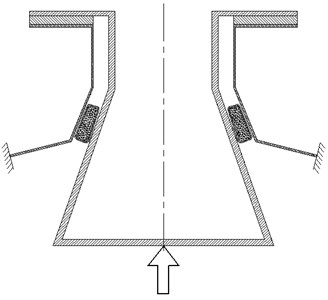
Fig. 25The schematic diagram of mechanism under situation one
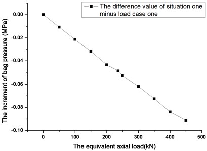
The results of mechanism under situation one and load case one are shown in Fig. 26 and Fig. 28, the difference value results of situation one minus load case one are shown in Fig. 27 and Fig. 29, plotted by the value of equivalent axial force on the horizontal axis.
According to Fig. 26, both of the curves almost coincide with each other, and Fig. 27 shows that the difference value curve of axial stiffness variation has bad linearity with loads though the difference value is too small when compared to the real value, indicating that load type has basically no effects on the axial stiffness variation when the same effects of axial forces generated by different types of loads imposed on the bottom of inner shell.
According to Fig. 28 and Fig. 29, both of the curves of pressure variation and difference value pressure variation have good linearity along with increasing axial loads. The corresponding difference value of increment of bag pressure decreases with the equivalent axial load, which indicates that the increment of bag pressure is smaller when mechanism is under pressure loads. Owing to larger scope regions that pressure loads act on, though both of concentrated load and pressure loads are imposed on the bottom of inner shell, there is more severe shrinkage deformation occurs in the radial direction of inner shell, which provides more space for the expansion of fluid bag, resulting in the less increment of bag pressure. Thus the factor of load type has effect on the increment of bag pressure variation, the larger equivalent axial force act on the inner shell, the less increment of bag pressure that pressure loads do.
Fig. 26The diagram of axial displacement of inner shell and axial load
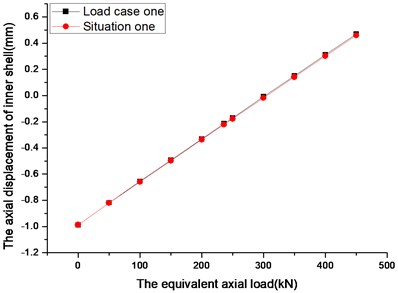
Fig. 27The diagram of axial displacement and axial load
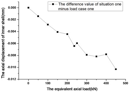
Fig. 28The diagram of increment of bag pressure and axial load
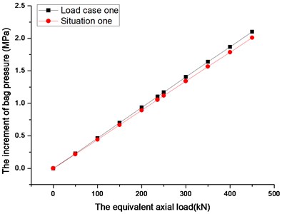
Fig. 29The diagram of increment of bag pressure and axial load
6.2. The factors of fluid bag and outer shell affecting the axial stiffness characteristics of mechanism
According to Section 6.1, the simulation results of mechanism under situation one is obtained. Adjusting the pressure loads to the surface of inner shell and fluid bag, the mechanism loaded in this way is defined as situation two. Similarly, adjusting the pressure loads to the surface of inner and outer shell, the mechanism loaded in this way is defined as situation three. The schematic diagram of mechanism subjected to situation two is shown in Fig. 30, the schematic diagram of mechanism subjected to situation two is shown in Fig. 31, the red bold lines represent the regions subjected to pressure loads.
The results of mechanism under different scope of pressure loads are shown in Fig. 32 and Fig. 34, the difference value results are shown in Fig. 33 and Fig. 35, plotted by the pressure loads on the horizontal axis.
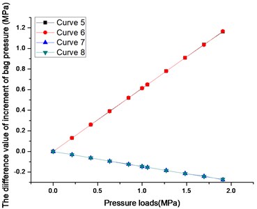
According to Fig. 32 and Fig. 34, the axial stiffness characteristics of mechanism under different scope of pressure loads are different. Considering the scope regions of pressure loads in situation one, situation two, situation three and load case two are different, the effect of pressure loads act on the surface of outer shell and fluid bag on axial stiffness characteristics of mechanism can be obtained by the way of subtraction.
Curve 1 in Fig. 33 and curve 5 in Fig. 35 are the difference value results of situation two minus situation one, which almost coincide with curve 2 and curve 6 of difference value results of load case two minus situation three. And from the pressure loads scope regions of situation one, situation two, situation three and load case two, it is found that both of the difference value results of situation two minus situation one and load case two minus situation three equal to the condition that only the surface of fluid bag in mechanism is subjected to pressure loads. Similarly, curve 3 and curve 7 as well as curve 4 and curve 8 represent the effect of pressure loads act on the surface of outer shell on axial stiffness characteristics of mechanism, both of them almost coinciding with one another respectively demonstrate the simulations hold water.
Fig. 30The schematic diagram of mechanism under situation two
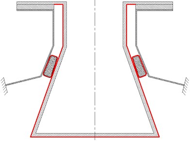
Fig. 31The schematic diagram of mechanism under situation three
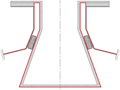
Fig. 32The diagram of axial displacement of inner shell and axial load
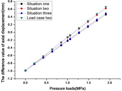
Fig. 33The diagram of axial displacement and axial load
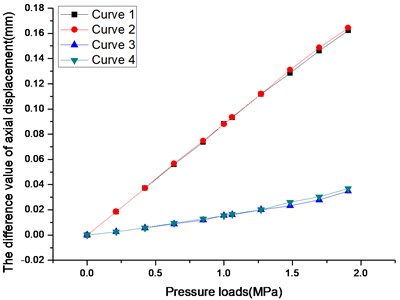
Thus according to Fig. 33, the larger pressure loads are imposed on fluid bag as well as outer shell surface, the more axial displacement of inner shell will be adjusted. According to Fig. 35, the increment of bag pressure increases with loads when the pressure loads are imposed on the surface of fluid bag, and the corresponding increment of bag pressure decreases with loads on the occasion that the pressure loads are imposed on the surface of outer shell.
When the pressure loads are imposed on the surface of fluid bag, fluid bag is not in balance any more since volume shrink occurs to increase pressure to offset the external force, thus the increment of bag pressure increases with loads. And the mechanism needs to re-adjust to a new equilibrium state due to the volume shrink of fluid bag, which results in increasing the axial displacement of inner shell.
When the pressure loads are imposed on the surface of outer shell, which makes the outer shell deform, and the deformation trend is making outer shell become warped upwards and expand in the radial direction. Due to the deformation of outer shell, there is more space available for fluid bag which is placed between in inner and outer shell to expand, which results in the volume inflation of fluid bag to decrease the bag pressure and increasing the axial displacement of inner shell to enter a new equilibrium state.
Fig. 34The diagram of increment of bag pressure and axial load
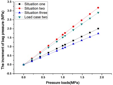
Fig. 35The diagram of increment of bag pressure and axial load
6.3. The comparison of factors affecting the axial stiffness characteristics of mechanism
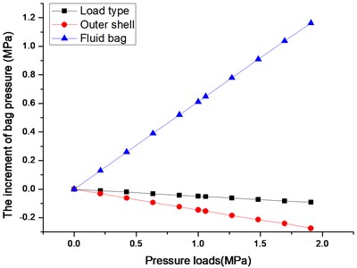
According to Section 6.1 and Section 6.2, the different factors affecting the axial stiffness characteristics of mechanism are discussed. The comparison of factors affecting the mechanism axial stiffness characteristics is shown in Fig. 36 and Fig. 37, plotted by the pressure loads on the horizontal axis.
Fig. 36The diagram of axial displacement and pressure loads
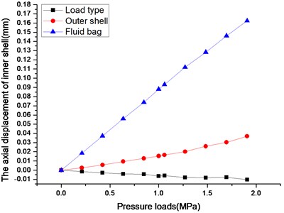
Fig. 37The diagram of increment of bag pressure and pressure loads
According to Fig. 36, the factor of load type has basically no effects on the axial stiffness variation, which means if the same effects of axial forces generated by different types of loads are imposed respectively on the bottom of inner shell, the axial displacement of inner shell is almost the same. The factor of fluid bag has the most significant effect for the axial stiffness variation.
According to Fig. 37, load type has small impact on the increment of bag pressure, both of the factors of load type and outer shell decrease the increment of bag pressure, and fluid bag is the key factor determining the increment of bag pressure since the bag pressure maintains growth when the pressure loads are imposed on the bottom of mechanism, which is consistent with the simulation result that the curve of increment of bag pressure variation caused by load case two is larger than the corresponding curves caused by load case one according to Section 5.2.
Therefore, it is indicating that fluid bag is the key factor determining the axial stiffness characteristics of mechanism of fluid bag shock absorber.
7. Conclusions
1) A mechanism of fluid bag shock absorber is designed for the axial protection of rubber joint and the structure of rubber joint and fluid bag is introduced. The finite element model of the mechanism is established, the different types of loads imposed on the bottom of mechanism when the mechanism works in different environment are described and the load stiffness matrix is obtained when pressure loads are applied to the mechanism.
2) The effects of the notch in fluid bag on axial stiffness characteristics of mechanism are discussed. Due to the existence of notch in fluid bag, the flip of inner shell occurs as the increasing axial concentrated load is imposed on the bottom of inner shell, but it basically has no effects on the increment of pressure and volume variations of bag.
3) The equivalent axial force generated by pressure loads imposed on the surface of inner shell is calculated, and a load corresponding principle is carried out for the convenience to compare the simulation results of mechanism under different types of loads. The results show that the axial displacement of inner shell as well as increment of bag pressure caused by pressure loads is larger than concentrated load.
4) The effects of different factors affecting the axial stiffness characteristics of mechanism are discussed. Load type has almost no effects on the axial stiffness variation, and has small impact on the increment of pressure variation of bag; Outer shell appears to be one of the crucial factors affecting the axial stiffness and increment of bag pressure variations, the axial displacement of inner shell increases slightly and the increment of pressure decreases with pressure loads; Fluid bag is the key factor determining the axial stiffness characteristics of mechanism, both of the axial displacement of inner shell and increment of bag pressure increase a lot with loads when the pressure loads are imposed on the surface of fluid bag.
5) The mechanism of fluid bag shock absorber is under small deformation when subjected to current range of working loads, linearity can be obviously observed in the mechanical characteristics of mechanism. With the increase of working loads imposed on the bottom of mechanism, the mechanical characteristics of mechanism may alter during the process, which will bring about nonlinearity and perhaps require further improvements in the analysis methods, it will be a research aspect in the future.
References
-
Shimozawa K., Tohtake T. An air spring model with non-linear damping for vertical motion. Quarterly Report of RTRI, Vol. 49, Issue 4, 2008, p. 209-214.
-
Zhang Liguo, Zhang Jiazhong, Jia Liping, Huang Wenhu, Zhang Xuewei Future and development of air springs. Journal of Vibration and Shock, Vol. 26, Issue 2, 2007, p. 146-151, (in Chinese).
-
Pak Kin W., Zhengchao X., Jing Z., Tao X., Feng H. Analysis of automotive rolling lobe air spring under alternative factors with finite element model. Journal of Mechanical Science and Technology, Vol. 28, Issue 12, 2014, p. 5069-5081.
-
Ziyue W., Wakui S., Nakamura Y. Control of an air spring type anti-vibration apparatus using minimal order observer. International Journal of Advanced Mechatronic Systems, Vol. 6, Issues 2-3, 2015, p. 84-97.
-
Haisu D., Liu X. The simulation and study of buffer device of hydraulic cylinder. Manufacturing Engineering and Automation Ii, Pts 1-3., Vol. 591, Issue 593, 2012, p. 561-564.
-
Peng S.-J., Zhou C., Yu C.-G. The numerical simulation of three-dimensional dynamic-mesh flow field of a hydraulic buffer. Advanced Materials Research, Vol. 588, Issue 589, 2012, p. 1264-1268.
-
Pang M., Wu R.-M., Xie M.-X. Simulation and experiment study of hydraulic buffer of track vehicle. Proceedings of the International Conference on Computational Intelligence and Software Engineering, 2009, p. 1-5.
-
Chen Q.-P., Shu H.-Y., Fang W.-Q., He L.-G., Yang M.-J. Fluid structure interaction for circulation valve of hydraulic shock absorber. Journal of Central South University, Vol. 20, Issue 3, 2013, p. 648-654.
-
Ming Z., Rui J., Hong N. Analysis of stiffness characteristics of a new fluid bag for axial shock protection. Journal of Vibroengineering, Vol. 17, Issue 2, 2015, p. 587-601.
-
Putra A., Norfarizan S., Samekto H., Salim M. A. Static analysis of a laminated rubber-metal spring using finite element method. Materials, Industrial, and Manufacturing Engineering Research Advances 1.1, Vol. 845, 2015, p. 86-90.
-
Salim M. A., Putra A., Thompson D., Ahmad N., Abdullah M. A. Transmissibility of a laminated rubber-metal spring: a preliminary study. Applied Mechanics and Materials, Vol. 393, 2013, p. 661-665.
-
Salim M. A., Putra A., Abdullah M.A. Analysis of axial vibration in the laminated rubber-metal spring. Materials, Industrial, and Manufacturing Engineering Research Advances 1.1. Vol. 845, 2014, p. 46-50.
-
Ma Y., Liang Z., Hong W., Zhang D., Jie H. Theoretical and experimental steady-state rotordynamics of an adaptive air film damper with metal rubber. Journal of Sound and Vibration, Vol. 332, Issue 22, 2013, p. 5710-5726.
-
Amin A. F. M. S., Bhuiyan A. R., Hossain T., Okui Y. Nonlinear viscosity law in finite-element analysis of high damping rubber bearings and expansion joints. Journal of Engineering Mechanics, Vol. 141, Issue 6, 2015, p. 1-11.
-
Xu Yanmin, Hao Wei. Analysis on static mechanical properties of air spring based on ABAQUS. China Rubber Industry, Vol. 62, Issue 1, 2015, p. 41-44, (in Chinese).
-
ABAQUS Theory Manual, Version 6.10, Dassault Systèmes Simulia Corporation, Providence, RI, 2010.
About this article

