Abstract
In this paper, we study the coupling dynamic characteristic of a single mass vibration machine driven by two eccentric rotors rotating oppositely. According to the coordinate of rotor flux, we deduce the electromagnetic torque of an induction motor in the steady state operation. From three ways of numerical analysis, model simulation and experiment, we discuss the coupling dynamic characteristic by using the actual parameters of this vibration machine. The results show that when the synchronization condition is satisfied, not only the vibration synchronization transmission can be achieved, but also the synchronization motion of the two motors with different power supply frequencies also can be achieved. The phase of the bigger mass-radius product lags behind that of the smaller one, the phase of the bigger distance between the rotation center of eccentric rotor and the mass center of the vibration rigid body lags behind that of the smaller one, and the phase difference decreases with increasing the synchronization velocity. We present a new method that adjusting the power supply frequencies of the two motors to make the vibration system with different structure parameters carry out the 0 phase difference, and its feasibility is verified by experiment.
1. Introduction
The self-synchronization vibration machine is widely used in petroleum, coal, metallurgy, chemical industry, food, etc. [1, 2], such as vibration conveyer and vibration screen. This type vibration machine driven by two eccentric rotors (ERs, also called exciter) is currently the most widely used vibration machine.
Huygens [3] first found the self-synchronization phenomenon in mechanical system by experiment that two pendulum clocks hung on the same beam. Blekhman [4-9] first proposed the self-synchronization theory of vibration machine driven by two ERs with nonlinear theory.
The mathematic methodology on dealing with self-synchronization are mainly the method of direct motion separation [4-9] and the averaging method of small parameters [1, 2, 10-14]. The former method has been proved to be useful and descriptive in establishing the conditions of existence and stability of self-synchronization in the vibration system. The later method selected the phase difference among ERs as the variable to simplify the analytical method for establishing the conditions of existence and stability of self-synchronization. The method was developed and generalized by scholars, who converted the synchronization of ERs to a problem on the existence and stability of 0 solutions for the average differential equations of small parameters over the average period.
There are also scholars who applied numerical analysis to solve the self-synchronization questions. Zhao et al. [10-14] applied the method of Four-order Rouge-Kutta to perform the simulation of the synchronization process of the vibration system. They discussed the effects of the system parameters on the condition of implementing frequency capture and the stability condition of the synchronization operation, which provided some references for the structural design of self-synchronization vibration machine. Balthazar et al. [15, 16] analyzed the non-linear phenomenon of self-synchronization and synchronization in pre-resonance and resonance region between a number of unbalanced dc motors inter acting with their flexible structural frame foundation response. Rumyantsev et al. [17] gave some comments on the non-linear dynamics of vibration transport machines by the numerical simulation. Yasuhiro [18, 19] applied shooting method to solve the displacement response curve of the vibration system to judge whether the system achieve synchronization. Miklos [20, 21] applied numerical simulation to study the coupling dynamic characteristic of self-synchronization, which makes it possible to produce vibrations with independently adjustable frequency and amplitude.
These above studies greatly deepen the understanding of self-synchronization, and put the self-synchronization research advance to a new level. Existing literatures have discussed self-synchronization from the aspect of energy transfer, and have also explained the synchronization process by numerical method. However, there are many problems have not been solved satisfactorily in the classic theory of self-synchronization, such as the vibration system can still maintain the synchronization operation when the power of a motor is cut off, and the vibration system is how to achieve the synchronization operation when the system parameters are not equal or same, etc. Moreover, the motor characteristics, and the frequency capture of the vibration system in the experiment is lack.
With the development of engineering technology, the technology of variable voltage and variable frequency (VVVF) is applied in the vibration machine. For example, we can adjust the vibration frequency or conveying speed by VVVF for different types of materials. In order to obtain the more accurate analysis results of self-synchronization, the effects of the motor parameters should be taken into account because the rotational velocities, the electromagnetic torques, and the currents of the motors will be changing in the synchronization process.
It is well known that the stronger ability of synchronization, the better symmetry of the vibration system parameter in many literatures. In fact, it is difficult to guarantee the symmetry because the limit of assembly level and processing precision, such as different physical parameter of the motor, the unequal structure parameter. Since the phase difference lead to the change of motion trace of the vibration machine, and only 0 phase difference, the machine can carry out the maximum efficiency and move in three directions, such as the linear vibration conveyer.
Base on the above questions of self-synchronization, we carry out the several works in this paper. First, we find the change rules of the phase difference with changing the parameters of the vibration system. Second, we discuss the coupling dynamic characteristic with different synchronization velocity. Lastly, we propose a new method to adjust the phase difference.
This paper is organized as follows. Section 2 gives the experimental model and theory results. Section 3 shows numerical results. Section 4 establishes simulation model. Section 5 presents the experiment results. Finally, we summarize our conclusion at the end of this paper.
2. Theory analysis
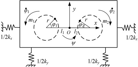
Fig. 1 illustrates the dynamic model of the vibration system, in which springs are connected to a rigid frame. The two vibration motors are symmetrically installed in the vibration rigid body rotating in the opposite direction to excite the vibration system. The frame is a fixed frame, and its origin is the equilibrium point of centroid of the vibration rigid body. The motions of the vibration rigid body are vibrations in - and - directions, denoted by and , and swing about its centroid, denoted by . Each eccentric rotors rotates about its spin axis, denoted by and . Using Lagrange’s equations, and letting the , , , and as the generalized coordinates, we obtain the motion differential equations of the vibration system described by the forms [10-14]:
where , , ; is the mass of the vibration rigid body; is the eccentric mass of the rotor ; is the distance between the rotational centre of the rotor and the mass centre of the vibration rigid body; is called the equivalent rotating radius of the vibration system about the centroid of the vibration rigid body; is the equivalent eccentric radius of the rotor ; , and are the constants of springs, and , and are the damping constants in -, - and -directions, respectively; is the moment of inertia of the eccentric rotor ; is the damping coefficients of the motor axes; are the electromagnetic torques of the motor; and denote and , respectively; Above mentioned, .
Fig. 1Dynamic model of the vibration system
For motor system, the mathematical model of an induction motor is a high-order, nonlinear and strong coupling multivariable system. When the motor operates in the steady state, the flux linkage is usually considered as a constant [22]. Letting the synchronization rotating coordinate of the rotor flux linkage as the reference coordinate, the electromagnetic torque of motor can be expressed as:
where:
and is the number of pole pairs; is the rotor flux linkage; is - axis stator current; is the stator resistance and is the rotor resistance; is the stator inductance, is the rotor inductance and is the mutual inductance; is the synchronous electric angular velocity and is the rotor electric angular velocity; is the phase voltage.
Then, the electromagnetic torque of motor can be express into another form, which is the function of and :
where:
If the variation coefficient of mechanical angular velocity of motor’s rotor is during the steady state operation of the vibration system, i.e., . Applying the first-order Taylor expression around , we can obtain the electromagnetic torque of motor in the steady state as follow:
where:
Base on the dimensionless coupling equation (also called frequency capture equation), and the rule of trigonometric function, we can obtain the synchronization condition as follow [10-14]:
where is called the synchronization torque (also called the torque of frequency capture), is the kinetic energy of eccentric rotor is the synchronization velocity of two motor, is the difference between the residual electromagnetic torques of the two motors, and , other parameters show in Appendix A.
We define ratio value between the synchronization torque and the load torque that the vibration system acts on the two motors as the coefficient of synchronization ability(CSA), . The greater CSA, the stronger the ability of synchronization of the vibration system:
When the vibration system operates in steady state, the load torques that it acts on the two motors are expressed as follows:
When the vibration system operates in the state of vibration synchronization transmission, we assume that power supply of motor 2 is cut off, , and the synchronization velocity is . So the condition of vibration synchronization transmission is expressed as follow:
The load torques of motor 1 with two work condition are expressed as follows:
where is the load torque of motor 1 when power supply of motor 2 is cut off and is the load torque of motor 1 when power supply of motor 2 continuously run.
We can obtain the difference of load torque between the two above conditions from Eq. (9), Because only motor 1 offers energy for vibration synchronization transmission, the synchronization velocity of vibration synchronization transmission state is slightly lower than that of two motor are supplied power at same time.
To sum up, the condition of vibration synchronization transmission must satisfy Eq. (8) and must satisfy the condition the load torque of the motor is less than the rated torque of that.
3. Numerical analysis of coupling dynamic characteristic
If the structure parameters are symmetric, the phase difference is 0, , and the load torques of the two motors are same, . But in fact, the physical parameters of the two motors and the structure parameters are not same or equal, so there is the transition process that the vibration system operates from de-synchronization to synchronization when the synchronization condition is satisfied. Next, our discussions all satisfy the synchronization condition.
If the masses of two ERs are not equal, we assume and the mass ratio . According to Eq. (7), we find that the first item in Eq. (1) is greater than that in Eq. (2). We assume the parameters of the two motors are same, . If the two motors operate in the synchronization state, their load torques must be equal, The synchronization reason is that the load torques of the two motors are equal due to the adjustment of the coupling sine function item .
Fig. 2 shows that the phase difference between two ERs of different masses changes with the synchronization velocity. The closer masses of two ERs, the smaller the phase difference. Since is the function of , the mass of ER 2 is smaller leads to the load torque act on motor 2 is smaller. To maintain synchronization state, the vibration system adjusts the value of the phase difference to balance the difference between the load torques of the two motors. It can be seen that since the synchronization torque increases with increasing the synchronization velocity, the phase difference also decreases according to Eq. (5).
Fig. 2Phase difference changes with synchronization velocity
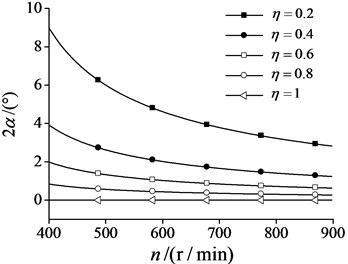
Fig. 3Synchronization torque changes with synchronization velocity
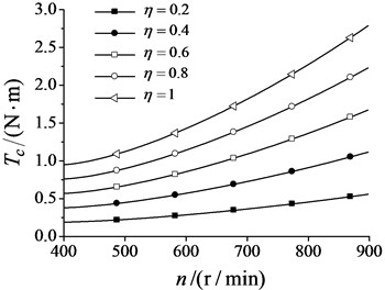
In the same way, since the synchronization torque is the function of the synchronization velocity, it increases with increasing the synchronization velocity as shown in Fig. 3. The closer masses of two ERs, the bigger the synchronization torque.
From Eq. (6) we can know that CSA is the function of the mass ratio and the cosine item of the phase different , and they belong to the denominator. CSA increases with increasing the synchronization velocity as shown in Fig. 4. The closer masses of two ERs, the bigger CSA.
Since the electromagnetic torque of the two motors are not equal with different motor parameters, , the difference between the residual electromagnetic torques of the two motors is not equal to 0, and the phase difference is not equal to 0. We assume the electromagnetic torque of motor 1 is greater than that of motor 2, and the mass of ERs are equal, . Since the adjustment of the coupling sine function item , the load torques of two motor are not equal, . The rotational velocity of motor 1 decreases with increasing its load torque, and that of motor 2 increases with decreasing its load torque at the same time. Base on the above coupling process, the vibration system operates in the steady state of a certain the phase difference.
From the above analysis, we can know that there must be a certain phase difference whether the structure parameters or motor parameters are not equal. By applying this coupling dynamic characteristic of the vibration system, we can make the vibration system carry out a certain motion with a certain phase difference. We also can obtain the 0 phase difference by adjusting power frequencies of the two motors to produce different electromagnetic torques when the structure parameters are not equal.
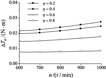
Fig. 5 shows the difference between the electromagnetic torques of the two motors(DET) when the 0 phase difference is produced by applying the above method. Since the load torque is the function of the synchronization velocity, DET increases with increasing the synchronization velocity. The closer masses of two ERs, the smaller DET.
Fig. 4Coefficient of synchronization ability changes with synchronization velocity
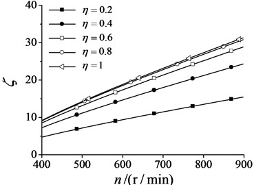
Fig. 5Electromagnetic torque difference changes with synchronization velocity
4. Numerical simulation model of the vibration system
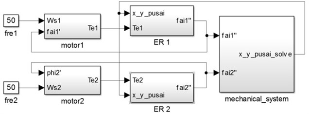
Based on the dynamic model of the vibration system and the electromagnetic torque formula of the induction motor, the simulation model of the single mass vibration system driven by two ERs is established by using the MATLAB/SIMULINK software. Fig. 6 shows the simulation model, the modules of motor1 and motor2 are built according to Eq. (3), the modules of ER 1 and ER 2 are built according to the last two formulas in Eq. (1), and the mechanical system module is built according to the first three formulas in Eq. (1).
Fig. 6Simulation model of the vibration system
Next, we will analyze the synchronization processes of the vibration system under different conditions. The actual parameters of the vibration machine in this paper are, 300 kg, 4 kg, 35 kg∙m2, 154000 N/m, 29000 N/rad, 270 N∙s/m, 34 N∙s/rad, 0.0001, 0.5 m, 0.05 m, 3, 25.4 Ω, 1.7 H, 1.15 H, 220 V.
4.1. Numerical simulation under different motor parameters
In this section, we will analyze the effects of the motor parameters on the synchronization process. Fig. 7 shows the parameter charts of the synchronization process under different motor parameters.
During the initial period in Fig. 7(a), the initial power frequencies of motor 1 and motor 2 are both 50 Hz, and motor 2 starts later 3 seconds than motor 1. Because motor 1 launches and motor 2 stops, the phase difference quickly increase, finally it periodic changes in (–180°,180°) in Fig. 7(b). After motor 2 starts, the synchronization velocity is close to 996 r/min in steady synchronization state. During the process of motor 2 tracing motor 1, due to the reduction of the velocity difference between the two motors, the phase difference also gradually reduce, and finally the two motors carry out synchronization motion with the 0 phase difference. This proves that the initial phase and velocity don’t affect the final motion state of the vibration system.
Fig. 7Parameters charts of the synchronization process under different motor parameters: a) The rotational velocities of the two motors, b) the phase difference, c) the electromagnetic torques of the two motors, d) Vibration in vertical x-direction, e) vibration in horizontal y-direction, f) vibration in swing ψ-direction
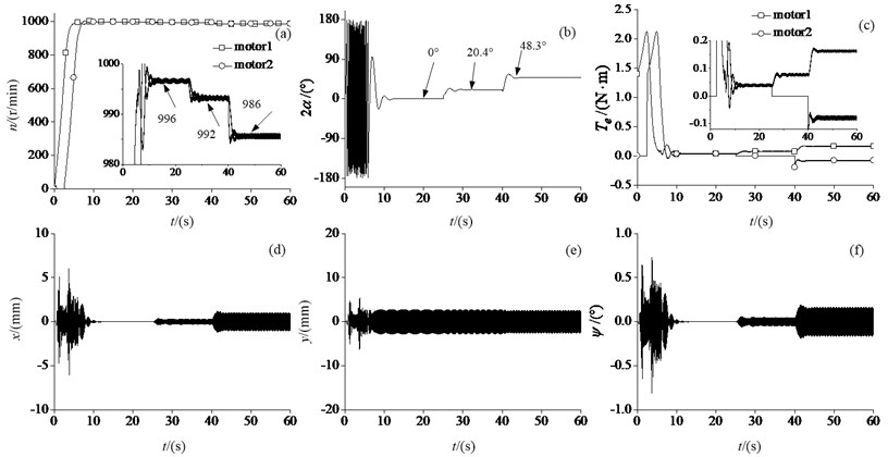
When the power of one motor is cut off during the process of the steady synchronization motion of the two motors, the vibration system continually operates in a new steady synchronization state. This phenomenon is called vibration synchronization transmission [1]. When the power of motor 2 is cut off at the 25 seconds, the synchronization velocity of the two motors rapidly decreases, and finally it is close to 992 r/min, the phase difference is about 21.5°. Vibration synchronization transmission has the following characters: before the disconnection of power the two motors have the exact same velocity, and after those until a new synchronization state is achieved, the velocities of the two motors are the same again but little lower than that before power disconnection, while the phase difference will increase but still maintain a fixed value.
The different physical parameters of the two motors and the fluctuation of the power can affect the rotational velocities of the two motors in steady state. When the power of motor 2 is connected and its power frequency is set to 49 Hz at the 40 seconds, the synchronization velocity is close to 986r/min and the phase difference is about 48.7°, which satisfy the synchronization condition because the phase difference is less than 90°. From last two typical cases, we can know that as long as satisfy the synchronization condition, the synchronization motion of the two motors can be achieved.
From Fig. 7(c), the actual velocities of the two motors are increasing because the increases of their electromagnetic torques during the initial period. After the rotational velocities of the two motors reach the actual rated velocities, their electromagnetic torques gradually decrease. When the rotational velocities of the two motors are close to equal, the vibration system achieves the synchronization motion with the effect of the synchronization torque. Since the adjustment function of the synchronization torque, the load torque of motor 1 is increased to decrease its velocity, and the load torque of motor 2 is decreased to catch up with motor 1, which results in a gradual reduction of the phase difference. When the rotational velocity of motor 2 is faster than motor 1, their load torques have a reverse change. Since the damping torques , the electromagnetic torques of the two motors are not equal to 0 in the steady state. From Fig. 7(a), we can find that when the vibration system operates in steady synchronization state, the rotational velocities and the electromagnetic torques of the two motors are not strictly the exact equal, but vary in a small range. During the process of the vibration synchronization transmission, because only motor 1 drives the vibration system after motor 2 is cut off, the electromagnetic torque of motor 1 becomes greater than that of motor 1 when the two motors working together. In the same way, because the rotational velocity of motor 1 with 50 Hz power frequency is greater than that of motor 2 with 49 Hz power frequency, the electromagnetic torque of motor 1 increases again with increasing its load torque. Meanwhile, the electromagnetic torque of motor 2 becomes a negative value because the function of the synchronization torque. The synchronization velocity of the two motors is greater than the rotational velocity of stator magnetic field of motor 2 with 49 Hz power frequency. In this case, we prove that the existence of the synchronization torque.
From Fig. 7(d)-(f), it can be fairly seen that when the time from 0 second to 10 seconds, the vibrations in the vertical, horizontal and swing directions experience a great transient process of oscillation because the working frequency of the vibration system passes its resonance region. After the steady synchronization operation, the phase difference is eventually reduced to 0, meanwhile, the vibrations in the horizontal and swing directions also converge to 0 gradually, finally only the vibration in the vertical direction remains. At the time, the vibration system achieves self-synchronization. The vibrations in the horizontal and swing directions increase with increasing the phase difference under last two cases.
4.2. Numerical simulation under different structure parameters
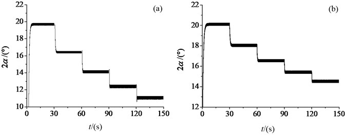
As shown in Fig. 8(a), we adjust the mass of ER 1 to 40 %. the phase differences are 19.7°, 16.5°, 14.3°, 12.4° and 11.1° under the different power frequencies 30 Hz, 35 Hz, 40 Hz, 45 Hz and 50 Hz, respectively. As shown in Fig. 8(b), we adjust the distance between the rotational centre of ER 1 and the mass centre of the vibration rigid body to 0.1 m. the phase differences between the two exciters are 20.1°, 17.9°, 16.6°, 15.4° and 14.6° under the different power frequencies 30 Hz, 35 Hz, 40 Hz, 45 Hz and 50 Hz, respectively. From the two typical cases, it is concluded that when the masses of ERs are not equal, the phase of the bigger mass lags behind that of the smaller one. When the distances between the rotational centers of ERs and the mass center of the vibration rigid body are not equal, the phase of the bigger distance lags behind that of the smaller one. Due to the moments of inertia of ERs increase with increasing the synchronization velocity, the phase difference reduces with increasing the synchronization torque. Because the change of the mass of ER directly affects its moment of inertia, the changing amplitude of the phase difference of the different masses is greater than that of the different distances.
Fig. 8Phase difference under different structure parameters: a) the different masses of two ERs, b) the different distances of two ERs
4.3. Numerical simulation under different power frequencies of the two motors
According to the change rules of the phase difference in Section 4.2, we can judge which one of two ERs is the leading phase from the sign of the phase difference value when there is the phase difference. According to the actual status to choose whether to increase the power frequency of the phase lagging motor or decrease that of the phase leading one.
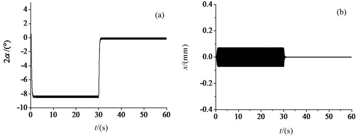
As shown in Fig. 9(a), when the distance between the rotational centre of ER 2 and the mass centre of the vibration rigid body is adjusted to 0.4 m, and the power frequencies of motor 1 and motor 2 are both 45 Hz, the phase difference is about -8.5° in the steady synchronization state. At the 30 seconds, the power frequency of motor 1 is set to 45.25 Hz, while the phase difference tends to 0 in the steady synchronization state. Fig. 9(b) shows the change of the vibration in -direction. From these typical cases, it is proved to be an effective method that the load torques of the two motors aren’t equal because the different structure parameters, which can be balanced by the different electromagnetic torques, finally the vibration system achieve the self-synchronization with the 0 phase difference.
Fig. 9Electromechanical coupling process under different power frequencies: a) the phase difference, b) vibration in horizontal x-direction
5. Experimental verification
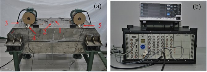
Fig. 10(a) shows the mechanical composition of the vibration machine, which consists of the two vibration motors, the vibration rigid, the four groups of spring and the support base. Fig. 10(b) shows the data signal collecting devices, the signals of the vibrations in the horizontal, vertical and swing directions, and the rotational velocities of the two motors are collected by B&K vibration testing. Meanwhile, the signal of the root mean square of motor 1 stator current is collected by HIOKI PW3335 power meter. Numbers 1-3 represent the testing positions of the acceleration sensors, and numbers 4-5 are velocity sensors in Fig. 10(a).
Fig. 10Experimental equipment a) vibration machine, b) data signal collecting devices
5.1. Experiment under different motor parameters
Fig. 11 shows the experimental results with the same schemes of numerical simulations in Section 4.1. The synchronization velocities of the two motors are close to 995 r/min, 991 r/min and 984 r/min under these three typical cases, and the phase differences are about 2.9°, 20.3° and 46.5°, respectively, which are close to the simulation results. The vibration machine due to machining and assembling can’t achieve high precision synchronization with the 0 phase difference, but it can be achieved the 0 phase difference in theory.
From Fig. 11(a), it is seen that the fluctuation of the velocity curves of the two motors with same power frequencies are highest, that of the two motors with different power frequencies is the second, and that of the vibration synchronization transmission is the smallest. This phenomenon also can be observed in Fig. 11(b). The reasons are that when there is a phase difference because of the external disturbance, the synchronization torque will join in the distribution of the load torques, which acts the driving torque on the phase lagging motor to increase its velocity and acts the load torque on the phase leading motors to decrease its velocity. Because the synchronization torque is smaller with a smaller phase difference, the changes of the rotational velocities of the two motors become frequent in the steady synchronization state. After the power of motor 2 is cut off, the fluctuation of the rotational velocities is slow because only one motor to drive the vibration system. During the last case, the synchronization torque always acts the load torque on motor 1 with higher power frequency, and acts the driving torque on motor 2 with lower one.
Fig. 11Experimental results under different motor parameters: a) the rotational velocities of the two motors, b) the phase difference, c) the current curve of motor 1’s stator, d) vibration in vertical x-direction, e) vibration in horizontal y-direction, f) vibration in swing ψ-direction
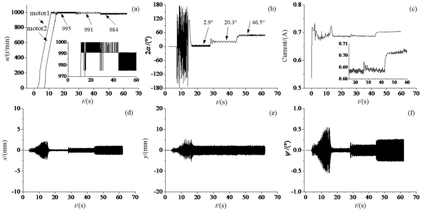
Fig. 11(c) shows the root mean square of stator current of motor 1. Due to the load torque of motor 1 is bigger at the beginning of power supply, there is a peak value on the current curve, and the current begins to decrease after motor 1 rotating. At 7 s, the current again exist a peak value because the power of motor 2 is supplied to increase the load torque of motor 1. Before the moment synchronization motion is achieved, the current once again exist a peak value because the phase of motor 2 lags behind that of motor 1. The synchronization torque acts the load torque on motor 1, which increases the current of motor 1. After the moment synchronization motion is achieved, the current curve becomes smooth, which illustrates the vibration system operates in the steady synchronization state because the load torque of motor 1is close to constant. From these three cases, it is seen that current value of the leading phase motor increases with increasing the phase difference, and current curve is smooth under the synchronization motion. According to the change of current, we can know that the change of the electromagnetic torque of the motor in vibration system. By observing the change of the current curve of the motor’s stator to study the self-synchronization is a good way.
Fig. 11(d)-(f) show the vibrations in the vertical, horizontal and swing directions. Due to the phase difference is not equal to 0, the vibrations in the horizontal and swing directions are existent. It is also seen that only the 0 phase difference, the machine can carry out the vibration in the vertical direction without others. It is beneficial to obtain the maximum excitation force.
To sum up, we can obtain the actual coupling dynamic characteristic of the synchronization process from this set experiment. The fluctuation of the velocity curves and the phase difference curves, we can know the existence of the synchronization torque. Moreover, the current reflect directly the change of the electromagnetic torque, which clearly illustrates the synchronization process.
5.2. Experiment under different structure parameters
We test two sets of different structure parameters to verify the correctness of simulation conclusions. One, we adjust the exciting force of ER 1 to 40 % by adjusting the overlap angle of the eccentric lumps, and the exciting force of ER 2 to 100 %. In fact, not only the mass of ER changes but also the equivalent radius changes with adjusting the overlap angle of the eccentric lumps. Another, the installation position of motor 1 is moved to the center of the vibration rigid. Form the comparison results between these two sets tests and simulation results of Section 4.2 in the Table 1, we can know that the change rules of the phase difference are same, which can provide the basis for engineering design, such as the inlet of screen needs the bigger exciting force and the discharge end of that needs the smaller exciting force.
Table 1Data comparison
Power frequency | Unequal masses of two ERs | Unequal positions of two ERs | ||
Simulation | Experiment | Simulation | Experiment | |
30 Hz | 19.7° | 20.9° | 20.1° | 20.7° |
35 Hz | 16.5° | 16.5° | 17.9° | 20.5° |
40 Hz | 14.3° | 14.0° | 16.6° | 18.7° |
45 Hz | 12.4° | 12.5° | 15.4° | 18.2° |
50 Hz | 11.1° | 11.6° | 14.6° | 17.4° |
5.3. Control 0 degree phase difference
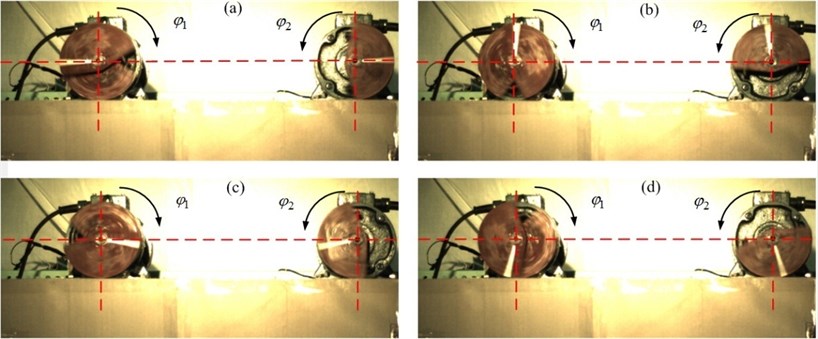
From the analysis of the Chapter 3 and Section 4.3, we have obtained numerically the 0 phase difference by applying the coupling dynamic characteristic. Next, we will verify the correctness of the method. We adjust the exciting force of ER 1 to 40 %, and that of ER 2 to 100 %. We adjust the distance between the rotational centre of ER 1 and the mass centre of the vibration rigid body to 0.4 m. Fig. 12 shows phases recorded by high-speed camera with same power frequency 50 Hz. the phase difference in Fig. 12 is about 27°. Fig. 13 shows phases recorded by high-speed camera with different power frequency, the power frequency of motor 1 is 49.6 Hz and that of motor 2 is 50 Hz. the phase difference in Fig. 13 is about 0°.
This group experiment good prove the feasibility of our method. It is helpful to engineering application to achieve a certain phase difference, such as the vibration machine can carry out several motion trace without changing the structure parameters.
Fig. 12Phases recorded by high-speed camera with same power frequency
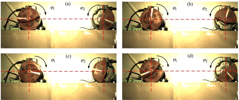
Fig. 13Phases recorded by high-speed camera with different power frequency
6. Conclusions
Taking a single mass vibration machine driven by two ERs rotating oppositely as the object, we study the coupling dynamic characteristic of self-synchronization from the three ways of numerical analysis, model simulation and experiment result.
Based on the simulation and experiment, it is concluded that when the synchronization condition is satisfied, the vibration synchronization can be achieved, and that of the two motors under different power frequencies also can be achieved. When the mass-radius products of two ERs are different, the phase of the bigger mass-radius product lags behind that of the smaller one. When the distances between the rotational centers of two ERs and the mass center of the vibration rigid body are different, the phase of the bigger distance lags behind that of the smaller one. The phase difference decreases with increasing the synchronization velocity with the above two cases. The above conclusions were verified by experiment.
We proposed a method that the vibration system carries out a certain motion with a certain phase difference with adjust the power frequencies of the two motors when synchronization condition is satisfied. The experiment results and numerical simulations proved that this method is useful and feasible. Moreover, the several typical cases of simulation and experiment can provide the basis for the adjustment of the phase difference, which is helpful to engineering application.
References
-
Wen B. C., Zhang H., Liu S. Y., et al. Theory and Techniques of Vibration Machinery and Their Applications. Science Press, Beijing, 2010.
-
Wen B. C., Fan J., Zhao C. Y., et al. Vibration Synchronization and Controlled Synchronization in Engineering. Science Press, Beijing, 2009.
-
Huygens C. Horologium Oscilatorium. Paris, France, 1673.
-
Blekhman I. I. Self-synchronization of vibrators in some types of vibrational machines. Inzhenerny Sbornik, Vol. 16, 1953, p. 49-72, (in Russian).
-
Blekhman I. I. Synchronization in Science and Technology. ASME Press, New York, 1988.
-
Blekhman I. I., Fradkov A. L., Nijmeijier H., et al. On self-synchronization and controlled synchronization. System and Control Letters, Vol. 31, 1997, p. 299-305.
-
Blekhman I. I. Vibrational Mechanics. World Scientific, Singapore, 2000.
-
Blekhman I. I., Fradkov A. L., Tomchina O. P., et al. Self-synchronization and controlled synchronization: general definition and example design. Mathematics and Computers in Simulation, Vol. 58, 2002, p. 367-384.
-
Blekhman I. I., Sorokin V. S. On the separation of fast and slow motions in mechanical systems with high-frequency modulation of the dissipation coefficient. Journal of Sound and Vibration, Vol. 329, 2010, p. 4936-4949.
-
Zhao C. Y., Zhu H. T., Wang R. Z., et al. Synchronization of two non-identical coupled exciters in a non-resonant vibration system of linear motion, part 1: theoretical analysis. Shock and Vibration, Vol. 16, Issue 5, 2009, p. 505-516.
-
Zhao C. Y., Zhu H. T., Wang R. Z., et al. Synchronization of two non-identical coupled exciters in a non-resonant vibrating system of linear motion, part 2: numeric analysis. Shock and Vibration, Vol. 16, Issue 5, 2009, p. 517-528.
-
Zhao C. Y., Zhao Q. H., Zhang Y. M., et al. Synchronization of two non-identical coupled exciters in a non-resonant vibration system of plane motion. Journal of Mechanical Science Technology, Vol. 25, Issue 1, 2011, p. 49-60.
-
Zhang X. L., Zhao C. Y., Wen B. C. Theoretical and experimental study on synchronization of the two homodromy exciters in a non-resonant vibrating system. Shock and Vibration, Vol. 20, 2013, p. 327-340.
-
Zhang X. L., Wen B. C., Zhao C. Y. Vibratory synchronization transmission of two exciters in a super-resonant vibrating system. Journal of Mechanical Science and Technology, Vol. 28, Issue 6, 2014, p. 2049-2058.
-
Balthazar J. M., Palacios J. L., Reyolando M. B. Some comments on the numerical simulation of self-synchronization of four non-ideal exciters. Applied Mathematics and Computation, Vol. 164, 2005, p. 615-625.
-
Balthazar J. M., Palacios J. L., Reyolando M. B. Short comments on self-synchronization of two non-ideal sources supported by a flexible portal frame structure. Journal of Vibration and Control, Vol. 10, 2004, p. 1739-1748.
-
Rumyantsev S., Tarasov D. Numerical Simulation of Non-linear Dynamics of vibration transport machines in case of three independently rotating vibration exciters: recent advances in applied mathematics. Proceedings of the American Conference on Applied Mathematics (AMERICANMATH 10), Harvard University, Cambridge, USA, 2010, p. 191-194.
-
Yasuhiro B., Tomoki O., Takahiro K. Development of a generation mechanism of synchronous vibration suitable for hand-held vibrating tools: investigation of an impact model with two oscillators. Journal of System Design and Dynamics, Vol. 5, Issue 6, 2011, p. 1361-1370.
-
Yasuhiro B., Takahiro K., Tomoki O. Development of a tamping rammer using self-synchronization phenomena. 14th Asia Pacific Vibration Conference, Vol. 5, 2011, p. 1473-1482.
-
Miklo A., Szabo Z. Mechanical synchronization in dual-rotor vibroactuator. Journal of Applied Mathematics and Mechanics, Vol. 13, 2013, p. 41-42.
-
Miklo A., Szabo Z. Simulation and experimental validation of the dynamical model of a dual-rotor vibrotactor. Journal of Sound and Vibration, Vol. 334, 2015, p. 98-107.
-
Chen J. Mathematical Model and Speed Adjustment System of Alternating Motors. Defense Press, Beijing, 1989.
About this article

This study was supported by the National Natural Science Foundation of China 51375080.
Xiaozhe Chen conducts the work for simulation and experiment analysis and paper writing; Xiangxi Kong contributes to experiment data; Jingxi Dou is responsible for the paper examination and proofreading; Yunshan Liu presides over languages embellish; Bangchun Wen grasps the macroscopic direction of the paper and offer technical guidance for programming.
