Abstract
A novel type of hybrid ultrasonic motor using longitudinal and torsional vibration modes is presented, which has four side panels uniformly distributed along the circumference of the stator cylinder. There is rectangle piezoelectric ceramics (PZTs) based on effect bonded on both sides of each side panels, which can be used to convert the first bending vibration mode of the side panels into the second torsional vibration mode of the stator when the exciting voltage is applied. Meanwhile, there are rectangle PZTs based on effect bonded on the surfaces of the stator cylinder between every two side panels, which can be used to excite the first longitudinal vibration mode of the stator. The simulation results using finite element method (FEM) software Workbench reveals the suitable polarization arrangement of PZTs and the final designed structure of the motor. The appearance size of the prototype is 28.2 mm×28.2 mm×68 mm, while the outer diameter of the stator cylinder is 20 mm. The major vibration and mechanical characteristics of the prototype have been measured. The working frequency of the prototype measured in experiment is around 43.12 kHz, which is consistent with the numerical results. When operating voltage of 350 Vp-p is applied, the no-load speed of the prototype is 103 rpm and the stalling torque is 48 mN·m.
1. Introduction
Ultrasonic Motors (USMs) [1-3] have been developed as a new concept of motors since the 1980’s. It utilizes the vibration of the elastic body in the ultrasonic frequency band and the converse piezoelectric effect of piezoelectric materials. The mechanical movement and torque are obtained by means of the friction contact force between the stator and rotor or slider. Since USMs developed by Sashida were commercialized [4], this new concept motor aroused the interest of researchers [5-7]. As the most successful commercial application of USMs, it is widely used in the precision micro-robots. In 1988, a new series of USMs for the precision micro-robots were proposed by K. Ragulskis [8].
USM using longitudinal-torsional hybrid vibration (LTUM) is a significant type of ultrasonic motors [9-13]. The longitudinal and torsional vibrations are combined to generate the elliptic motions of particles on a driving surface. The rotor is driven by the friction force between the stator and rotor. While the motor operates, the contact area between the stator and rotor covers the whole end surface of the stator, which allows the motor to yield greater output torque. The research on LTUM also can be traced back to 1980’s. Ueha have developed some types of LTUMs since 1988, such as a type of LTUMs which took advantage of large deformation of stack vibration in combination with the torsional vibrator and a type of LTUM using sandwich piezoelectric stator to substitute for multi-layer piezoelectric stator. Since 1992, Tomikawa has carried out numerous studies on the main types of LTUMs [14]. There are also some research achievements on LTUM in China in the last 15 years. For most types of LTUMs mentioned above, the torsional vibration piezoelectric ceramic (PZT) based on effect is used for exciting the shear vibration of the stator, which is polarized along circumference direction. However, the application of the torsional vibration PZT is limited by complex processing techniques and expensive in construction. In 1998, a LTUM using mode conversion whose torsional vibration is converted from longitudinal vibration has been proposed by Tsujino [15], and just longitudinal vibration PZT is used in this type of LTUM, but this type of LTUM can only rotate in a fixed direction.
In order to reduce the cost and expand the usable range of the LTUM, a new concept for designing the LTUM with no torsional vibration PZT and bidirectional rotation is presented in this paper. Based on the concept, a novel type of LTUM is proposed, which has four side panels uniformly distributed around the stator cylinder. There are rectangle PZTs based on effect bonded on both sides of each side panel, which can be used to convert the first bending vibration mode of the side panels into the second torsional vibration mode of the stator when the exciting voltage is applied. But at the same time, there are rectangle PZTs based on effect bonded on the surfaces of the stator cylinder between every two side panels, which can be used to excite the first longitudinal vibration of the stator.
2. Constructions
The novel type of LTUM mentioned above contains a stator and two rotors, as shown in Fig. 1. It is composed of the stator, rotors, shaft and pro-pressure devices. There are the same rotor structures on the both sides of the motor. The rotors are pressed on the driving surface of the stator by the pro-pressure devices through the shaft. The pro-pressure device is composed of the silicone rubber, clamp and nuts. There are friction materials bonded on the driving surfaces of the rotors, which consists of 10 % Al2O3, 10 % pressure thermit welding (PTW) and 80 % Epoxy resin (Ep). The thickness of the friction material is about 20 m and it is useful for increasing the torque of the motor and driving the rotors more stably. The silicone rubber has super non-linear elastic characteristics during a vibration cycle [16], which is much better to obtain stable output torque and shorten axial dimension of the motor than using the coil spring.
Fig. 1Construction of the novel type of LTUM with side panels
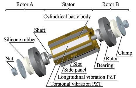
The stator is composed of a cylindrical basic body, four side panels uniformly distributed around the cylindrical basic body, and rectangle PZTs based on effect bonded on both sides of each side panel and on the surfaces of the stator cylinder between every two side panels, which are named as torsional vibration PZT and longitudinal vibration PZT, separately. When the torsional vibration PZTs are excited by AC voltage with suitable frequency, the first bending vibration mode of the side panels is obtained, which can be converted to the second torsional vibration mode of the stator; and when the longitudinal vibration PZT are excited by AC voltage with suitable frequency, the first longitudinal vibration mode of the stator is obtained. There are four bump structures on both the end surfaces of the stator, which are cut off flush with the four side panels and used for driving the rotors pressed on them.
There are two bearings set in the inner end surfaces of the stator, which are used to support the shaft, and the rotors are pressed on the end surfaces of the stator through the shaft. The rotor is composed of nuts, clamp, silicon rubber spring and the rotor base, the nut is screwed to the end of the shaft and used to press the clamp and the silicon rubber spring for controlling the magnitude of preload between the stator and rotor.
Phosphor bronze is chosen for the cylindrical basic body and the four side panels. Piezoelectric ceramic material used in the motor is PZT-8H. 45 steel (45#) is used for the rotor and shaft. Teflon is used for the bearing. The relevant material properties are list in Table 1.
Table 1Material constants
Material | PZT-8H | Phosphor bronze |
Density (kg/m3) | 7650 | 8850 |
Poisson’s ratio | 0.31 | 0.34 |
Elastic modulus (×109 N/m2) | 117 | |
Piezoelectric constant (C/m2) | ||
Mechanical quality factor, | 800 | |
Electromechanically coupling factor, | 0.6 |
3. Operation principles
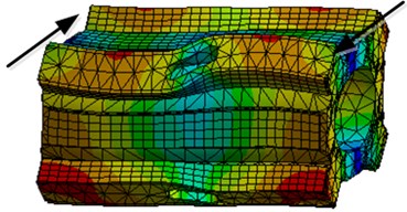
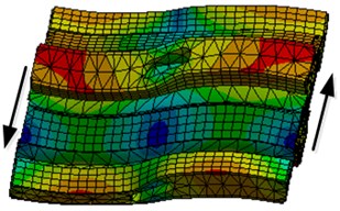
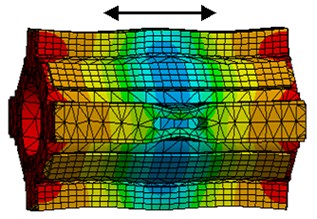
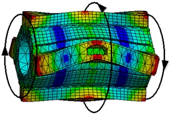
The first longitudinal and the second torsional vibration modes of the stator are employed to driving the rotors, as shown in Fig. 2.
Fig. 2Vibration modes of the stator
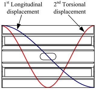
Fig. 3Distribution of the polarization directions of the PZTs
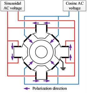
As the cylindrical basic body and the side panels vibrate as a whole, the first longitudinal vibration mode of the stator is excited by the longitudinal vibration PZT and the second torsional vibration mode of the stator is converted from the first bending vibration of the side panels exited by the torsional vibration PZT. The distribution of the polarization direction of the piezoelectric ceramics are shown in Fig. 3, the longitudinal vibration PZTs are bonded on the surfaces of the stator cylinder between every two side panels which are polarized along radial direction, and the torsional vibration PZTs are bonded on both sides of each side panel which are polarized along the circumference direction, however, each pair of the torsional piezoelectric ceramics on each side panel has same polarization direction.
Taking one side panel as an example, when a sinusoidal AC voltage with the nature frequency of the second torsional vibration mode is applied to both torsional vibration PZTs on the side panel, one of the torsional vibration PZT will extend while the other will contract simultaneously, then the side panel will present the first bending vibration mode. In this way, all the side panels are working together to excite the second torsional vibration mode of the stator, which is converted from the first bending vibration modes of the side panels. When a cosine AC voltage at the same frequency is applied to the longitudinal vibration PZTs, the first longitudinal vibration mode of the stator will be excited. Due to the orthogonal propagation of the first longitudinal and the second torsional vibration modes in the stator, the particle on the two driving surfaces of the stator generate symmetric elliptical motions which can be used to drive the rotors.
4. Simulations and analysis
There are some key points in the design of the motor. First, the nature frequencies of the first longitudinal vibration mode and the second torsional vibration mode should be as same as possible. Second, in order to obtain good characteristics, the particle vibration amplitude of the first longitudinal vibration mode and the second torsional vibration mode must be optimized. Since the longitudinal amplitude supports the output torque of the motor and the torsional amplitude controls the speed of the motor, the longitudinal and torsional amplitudes should be maximal simultaneously in the design. Third, the frequencies of the non-working interference vibration modes should keep away from that of the working modes. The structural parameters of the stator are shown in Fig. 4. In the design, the diameter is set as 20 mm and the diameters are decided by the bearing used in the motor. The simulation of the stator is carried out by FEM software Workbench.
Fig. 4Structure of the stator
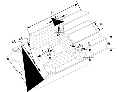
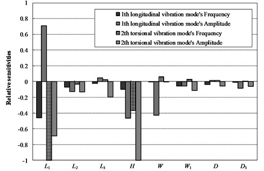
In order to solve the problem of frequency consistency, some structure parameters of the stator which influence the operation frequency greatly are chosen firstly by sensitivity analysis. From Fig. 4, the whole stator has twelve structure parameters, among which the sizes of , , and are fixed, that is, the diameter of the cylindrical basic body and bearing bore are fixed. Therefore, only eight structure parameters , , , , , , , and are selected to carry out the sensitivity analysis. The initial values of structural parameters of the stator are shown in Table 2, by which the FEM model can be established. When applied 100 Vp-p voltage on the PZT pieces and each parameter perturbs by 10 % of itself, the relative sensitivity of the frequencies and the amplitudes of the particle on the end surface of the stator for the longitudinal and torsional vibration modes can be solved, as shown in Fig. 5. According to the results in Fig. 5, the frequencies and the amplitudes of the working modes are mainly under the influence of the height , , and the width of the side panel. Thus, , , and can be chosen as the design parameters to solve the problem of frequency consistency, and the effects of these sizes on the amplitudes are also considered.
The final designed structural parameters of the stator listed in Table 3 are determined by simulation. The natural frequency of the first longitudinal vibration mode calculated in FEM software Workbench is 43.259 kHz and that of the second torsional vibration mode is 43.21 kHz, the difference of them is acceptable. The prototype is manufactured and the size of the prototype is 28.2 mm×28.2 mm×68 mm.
Table 2Initial values of structural parameters of stator (unit: mm)
Parameter | ||||||||||||
Value | 30 | 8 | 6 | 20.2 | 3 | 20 | 12 | 5 | 5.6 | 4 | 5 | 3 |
Table 3Final designed structural parameters of stator (unit: mm)
Parameter | ||||||||||||
Value | 40 | 12 | 6.6 | 20.2 | 3.5 | 20 | 12 | 6 | 5.6 | 4.1 | 5 | 3 |
Fig. 5Relative sensitivities of the frequencies and the amplitudes for the longitudinal and torsional vibration modes
The simulation results show that there are four vibration modes at frequencies from 40 kHz to 45 kHz, as shown in Fig. 6. It can be found that the first two modes are the non-working interference vibration modes, and the frequency difference from the working vibration modes is about 1.2 kHz, which is far enough for the motor to work properly.
5. Experiments
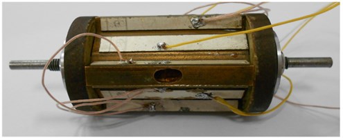
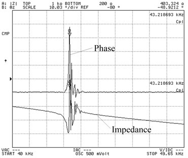
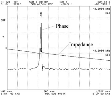
Based on the motor design mentioned above, the prototype has been manufactured, as shown in Fig. 7. The appearance size of the prototype is 28.2 mm×28.2 mm×68 mm, while the outer diameter of the stator cylinder is 20 mm. The working resonance frequencies of the prototype are measured by precision impedance analyzer Agilent 4294A with driving voltage 0.5 V0-p. The result is shown in Fig. 8. It shows how the impedance and phase of the stator change when the frequency varies from 40 to 50 kHz. Fig. 8(a) and (b) show a dip of the impedance and the phase peak at around 43.2 kHz.
Fig. 6Vibration modes at frequencies from 40 kHz to 45 kHz
a) 42.038 KHz
b) 42.040 KHz
c) 43.210 KHz
d) 43.259 KHz
Fig. 7The prototype of the motor
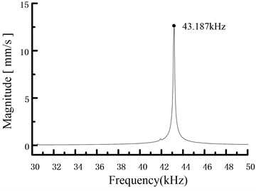
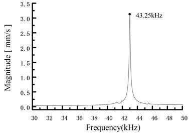
The frequency response of the stator is measured by using a PSV-300F-B Doppler laser vibrometer, as shown in Fig. 9. The comparison between the experimental results and the calculation results by the FEA software Workbench is shown in Table 4. It shows that there is little difference between the calculation frequency and the actual frequency mainly because of two reasons. First, the metal elastic body and the PZTs are taken as a whole in modal analysis while actually the PZTs are bonded on the metal elastic body. Second, the discontinuity of materials and machining tolerance result in the difference. However, the difference can be decreased further by optimal design of the stator in future work.
Table 4Calculation results and experimental results of the stator modal frequency (unit: Hz)
Operation modes | Calculation results | Experimental results | Differences |
First longitudinal mode | 43210 | 43187 | 13 |
Second torsional mode | 43259 | 43250 | 9 |
Differences | 49 | 63 |
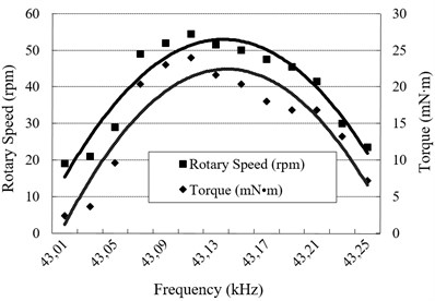
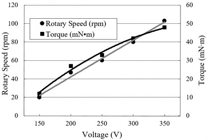
The important mechanical characteristics of the prototype are how the output performance changes according to the driving frequency and voltage amplitude. Fig. 10(a) shows how the rotor’s rotation speed and torque change when the driving frequency varies from 43.01 to 43.13 kHz at 200 Vp-p operating voltage. Fig. 10(b) shows the change in the rotation and the torque when the driving voltage amplitude varies from 150 to 350 Vp-p at a constant frequency 43.12 kHz. It can be seen that the no-load rotation speed can reach 103 rpm and the stalling torque can reach 48 mN·m. The results show that the rotation speed and torque increase roughly in proportion to the driving voltage amplitude.
Fig. 8Frequency characteristics of the impedance and the phase: a) The longitudinal vibration PZTs are excited, b) the torsional vibration PZTs are excited
a)
b)
Fig. 9Frequency response of the stator
a)
b)
Fig. 10a) Relationship between the output performance and the frequency at 200 Vp-p voltage, b) relationship between the output performance and the voltage at 43.12 kHz
a)
b)
6. Conclusion
A novel type of LTUM is presented, which has four side panels uniformly distributed along the circumference of the stator cylinder. The construction of the motor is proposed. The operation principle is also discussed, the second torsional vibration mode of the stator is converted from the first bending vibration mode of the side panels, and the first longitudinal vibration and second torsional vibration mode of the stator are all excited by rectangle PZTs based on effect. The simulation is carried out by using FEM software Workbench, the results reveals the suitable polarization arrangement of PZTs and the sensitivity analysis is presented, the final designed structural parameters of the stator are obtained. The appearance size of the prototype is 28.2 mm×28.2 mm×68 mm, while the outer diameter of the stator cylinder is 20 mm. The major vibration and mechanical characteristics of the prototype have been measured. The working frequency of the prototype measured in experiment is around 43.12 kHz, which is consistent with the numerical results. When operating voltage of 350 Vp-p is applied, the no-load speed of the prototype is 103 rpm and the stalling torque is 48 mN·m.
References
-
Kurosawa M., Ueha S. High speed ultrasonic linear motor with high transmission efficiency. Ultrasonics, Vol. 27, Issue 1, 1989, p. 39-44.
-
Hagedorn P., Wallaschek J. Travelling wave ultrasonic motors, part 1: working principle and mathematical modelling of the stator. Journal of Sound and Vibration, Vol. 155, Issue 1, 1992, p. 31-46.
-
Morita T., Kurosawa M., Higuchi T. An ultrasonic micromotor using a bending cylindrical transducer based on PZT thin film. Sensors and Actuators A, Vol. 50, Issue 1, 1995, p. 75-80.
-
Sashida T. Trial construction and operation of an ultrasonic vibration driven motor. Oyo Butsiuri, Vol. 51, Issue 6, 1982, p. 713-718.
-
Fleischer M., Stein D., Meixner H. New type of piezoelectric ultrasonic motor. IEEE Transactions on Ultrasonics, Ferroelectrics and Frequency Control, Vol. 36, Issue 6, 1989, p. 614-619.
-
Ohnishi O., Myohga O., Uchikawa T., Tamegai M., Inoue T., Takahashi S. Piezoelectric ultrasonic motor using longitudinal-torsional composite resonance vibration. IEEE Transactions on Ultrasonics, Ferroelectrics, and Frequency Control, Vol. 40, Issue 6, 1993, p. 687-693.
-
Bao X. Q., Ounaies Z., Varadan V. K., Varadan V. V. Active noise-control using piezoelectric actuator for a machine. Smart Materials, Vol. 2189, 1994, p. 211-223.
-
Ragulskis K. M., et al. Vibromotors for Precision Microrobots. Hemisphere Publishing Corporation, 1988.
-
Kurosawa M., Nakamura K., Ueha S. Numerical-analysis of the property of a hybrid transducer type ultrasonic motor. IEEE Proceedings of Ultrasonics Symposium, Vols. 1-3, 1990, p. 1187-1190.
-
Kurosawa M., Ueha S. Hybrid transducer type ultrasonic motor. IEEE Transactions on Ultrasonics, Ferroelectrics and Frequency Control, Vol. 38, Issue 2, 1991, p. 89-92.
-
Tsujino J., Takeuchi M., Koshisako H. Ultrasonic rotary motor using a longitudinal-torsional vibration converter. IEEE Proceedings of Ultrasonics Symposium, Vols. 1-2, 1992, p. 887-892.
-
Tsujino J., Suzuki Yasojima R. H. Load characteristics of ultrasonic rotary motor using a longitudinal-torsional vibration converter. IEEE Proceedings of Ultrasonics Symposium, Vols. 1-2, 1996, p. 377-382.
-
Nakamura K., et al. An optimum design for the hybrid transducer ultrasonic motor in symmetrical structure. IEEE Proceedings of Ultrasonics Symposium, Vol. 1, 1998, p. 703-706.
-
Tomikawa Y., et al. Some constructions and characteristics of rod-type piezoelectric ultrasonic motors using longitudinal and torsional vibrations. IEEE Transactions on Ultrasonics, Ferroelectrics and Frequency Control, Vol. 39, Issue 5, 1992, p. 600-608.
-
Tsujino J., Ueoka T. Vibration characteristics of one-dimensional longitudinal-torsional converter with multiple slitted parts. IEEE Proceedings of Ultrasonics Symposium, Vol. 1, 1998, p. 723-728.
-
Tsujino J., Suzuki A. Load characteristics of ultrasonic motor with a longitudinal-torsional converter and various nonlinear springs for inducing static pressure. IEEE Proceedings of Ultrasonics Symposium, Vols. 1-2, 2001, p. 545-550.
Cited by
About this article

The work was supported by National Natural Science Foundation of China (Grant No. 51205203), the Fundamental Research Funds for the Central Universities (No. 56XCA15001).
