Abstract
Ultrasonic horns are used in the ultrasonic-assisted milling and cutting tools. However, the interaction with tool end vibrations deteriorates the horn performance. In this study, the amplification coefficients and vibration node locations of an ultrasonic horn were determined via the 1D wave theory and optimized by the tool load effect account. By arranging spiral grooves at the straight part of the ultrasonic horn, a longitudinal-torsional modal converter was introduced. This made it possible to convert longitudinal vibrations into longitudinal-torsional coupled ones by the superposition of incident and reflected longitudinal waves with reflected transverse ones at grooves. Orthogonal L9 (33) tests with parameters of spiral grooves as variables were designed and conducted, and longitudinal-torsional ratios (LTR) of the milling tool end under different conditions were assessed using the commercial ANSYS software package. The in-depth analysis of simulation results implies that the LTR values are controlled by the following influence factors in the decreasing order: helical angle, number of grooves, and groove width. Single-factor tests indicate that LTR exhibits an initial drop and a further rise with the helical angle, attaining its minimal value at 30°; it drops with the number of grooves n, and remains practically unchanged with the groove width variation. Finally, the vibration tests of the proposed horn with the optimized parameters corroborated its feasibility and demonstrated its excellent performance in the ultrasonic-assisted milling tool application.
1. Introduction
As a key functional component in ultrasonic vibration units, the ultrasonic horn is mainly responsible for the amplitude amplification and energy concentration [1, 2]. The horn vibration characteristics are assessed based on the wave theory, while particular solutions are determined by the respective boundary conditions. Such characteristics of ultrasonic horns as the amplification coefficients and node displacements are investigated by the modal analysis. Currently, common configurations of ultrasonic horns include the exponential, step-like, Gaussian, Fourier, catenary, coned, cosine, and clip types [3, 4]. Based on the cross-sectional shapes, horns can be classified as (i) single and (ii) cascade composite ultrasonic horns [5]. Moreover, based on the vibration modes, horns can be subdivided into longitudinal, torsional, flexural, and combined vibration types, which are also referred to as longitudinal bending, longitudinal-torsional, crankle, and double bending types [6, 7].
At present, various designs of ultrasonic horns are available for a wide range of applications, and their further modification is being substantiated by multiple scholars [8, 9]. For instance, Liang et al. determined the equivalent four-end network variables of cosine ultrasonic horns based on a study of cosine transition section of a step-like horn [10]. Zhao et al. deduced the equivalent circuits of coned and exponential transition sections of step-like composite horns, their respective frequency equations, and amplification coefficient equations based on the fundamental principles of four-end networks [11]. Yang et al. designed coned transition step-like horns using the equivalent circuit method and provided the local resonance substantiation [12]. Rani et al. investigated the characteristics of cylindrical, step-like, Gaussian, catenary, and Bessel horns using the ANSYS software, as well as explored the temperature distribution for Bessel horns in the plastic welding process [13]. Feng et al. performed the modal analysis of coned transition step-like horns using the Inventor (free mechanical design and 3D CAD) software and obtained the results, which made it possible to improve the horn efficiency and optimize its design [14]. Lai et al. used the Autodesk Algor Simulation software to simulate the performance of cascade horn systems, which approach was also found quite effective for the horn design and accuracy optimization [15]. Mori et al. simulated a short column vibrator by the apparent elasticity method as applied to vibrations of homogeneous solid cylinders, and obtained the numerical simulation results, which were highly consistent with the available experimental data [16]. Ren et al. investigated 2D and 3D coupled vibrations of various piezoelectric vibrators using the apparent elastic method and proposed the resonance frequency equation for vibrators [17, 18]. Lin [19] derived longitudinal vibration frequency equations for a number of single horns and performed the design calculations of horns with rectangular sections.
Currently, the horn design is based on the half-wave and zero-load, with the adjustment performed on the basis of practical considerations. However, in the machining tool operation practice, horns receive input excitations from the transducer and are connected to the machining tools, the excitation of which may interfere with the horn ultrasonic vibrations. To fully consider the effects of the above ultrasonic vibrations on the machining tool performance and use the results obtained for enhancing the ultrasonic machining accuracy, this study is focused on the design of longitudinal-torsional ultrasonic step-like horns with tool loads under single excitation, as well as on the optimization of horn geometric parameters using ANSYS software. The ultrasonic system, comprising the proposed horn connected to transducer and milling tools, was installed in the material processing center, and the experimental results corroborated an excellent vibration performance of the proposed horn design.
2. Calculations of vibrations of step-like horns connected to milling tools
According to the 1D ultrasonic wave equation, milling tools are reduced to loads acting on the horn, whereas the materials of the horn and milling tools are considered homogeneous and isotropic [20, 21]. With disregard of the mechanical losses and transverse vibrations, the equation for axial vibration waves in a step-like horn can be reduced to the following form:
where is the displacement of a particle in the horn, is the horn cross-sectional area, is the circular wave number and, while is the speed of medium longitudinal wave in the horn (), is the circular frequency, is the abscissa of a point, is the horn elastic modulus, and is the horn density.
Fig. 1 shows the configuration of the step-like horn with the milling tool, whose general-type vibrations are described by the following equation:
Among them, , is area, , and are the acoustic impedance of Ⅰ, Ⅱ, Ⅲ. and are supposed to be the stress distribution function of the horn.
The milling tool was installed at the location corresponding to length , and its resonance frequency can be derived via Eq (3):
Substitution of Eq (4) into Eq (3) yields:
Insofar as the horn is connected to the transducer at one end, its diameter at this end is equal to that of the transducer ( 30 mm). At the other end, the horn is connected to the tool with the M19 nut of internal diameter of 19 mm. Therefore, the small end diameter of the horn () and the selected rose cutter diameter () are equal to 19 and 8 mm, respectively.
Fig. 1Stepped horn with tool
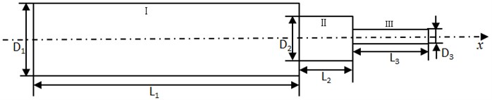
Considering the consistency of the horn and ultrasonic tool system, it is defined that + 3/4 and the transition of and is arc-shaped. Therefore, the flange connected to the ultrasonic tool system was set at 1/4 . Fig. 2 depicts the horn dimensions.
Fig. 2Basic size of horn
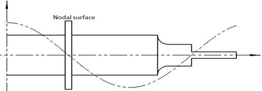
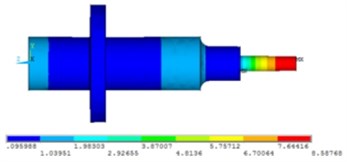
Based on the designated vibration system parameters depicted in Fig. 3, the vibration system model was elaborated using Pro/Engineer 3D CAD software (which product was recently renamed to PTC Creo) by Parametric Technology Co. (US). The boundary conditions was set at 1/4 (nodal surface). The modal analysis was performed by introducing the entity model into the ANSYS commercial software package with the finite elements of Solid 186 type. After meshing, the numerical simulation model was conducted and longitudinal vibration modes for the frequency range from 32 to 38 kHz were obtained, as shown in Fig. 4.
Fig. 3Three-dimensional model
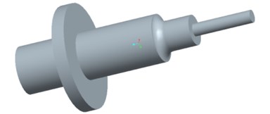
Fig. 4Displacement nephogram of horn
Generally, horns are made of metallic materials, including various steels, brass, aluminum, and titanium alloys. On the one hand, titanium alloys exhibit excellent mechanical properties but are limited by high cost and poor machinability. On the other hand, aluminum alloys are cost-effective and have good mechanical characteristics but have poor resistance to corrosion under ultrasonic cavitation conditions, Steels and brass are cost-effective and easy to process but exhibit severe material losses during their processing. Therefore, the grade 45# medium-carbon steel in cylindrical blanks was selected for the proposed horn manufacturing [22]. Table 1 summarizes its physical parameters.
Table 1The physical properties of 45# steel
Material | Density (Kg/m3) | Elasticity modulus (GPa) | Sound velocity (m/s) | Poisson ratio |
45#Steel | 7800 | 210 | 5170 | 0.28 |
Insofar as flanges and arc-shaped transition sections were found to cause variations in the cylindrical step-like coupled vibration mode of the initial vibration system, the extension of the milling tool was tuned, the locations of displacement nodes were adjusted, and the displacements of flanges and joints were minimized via the modal analysis, in order to reduce the energy losses/heat dissipation during the vibration process.
The numerical results on displacements obtained via ANSYS were obtained in the dimensionless (i.e., normalized by unit displacement) form. The interpretation of the modal simulation results revealed that the frequency of longitudinal vibration modal was 35.145 kHz, the larger end displacement was 3 μm, the milling tool displacement was 8 μm, and the amplification coefficient was 2.67, which fully satisfied the machining tool requirements.
3. Design of longitudinal-torsional horn
3.1. Mechanism of vibration mode conversion of longitudinal-torsional vibration horns
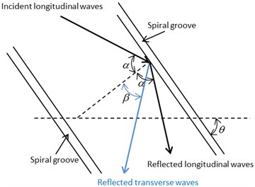
The modal conversion of spiral grooves is depicted in Fig. 5. By developing spiral grooves on the straight part, such effects as the superposition of incident longitudinal waves, reflected longitudinal waves, and reflected transverse waves at grooves can be achieved, resulting in the horn longitudinal-torsional coupled vibrations. Herein, the reflection angle of reflected longitudinal waves was , the reflection angle of reflected transverse waves was , and the spiral angle of groove was . According to the Snell law:
where is Poisson’s ratio of the material for making horn, and are speeds of the horn longitudinal and transverse waves, respectively.
Fig. 5Diagram of the conversion mechanism
Assume that force acting at the horn input end is split in the groove into the axial () and tangential () components:
According to the torsional vibration theory, tangential forces lead to torsional vibrations, whose torque can be assessed as follows:
where is the horn radius, is the cross-sectional area of the horn (), is the infinitesimal radius of any area, is the infinitesimal area of any area (), is the tangential force in the groove unit area:
As soon as propagating longitudinal waves reach the spiral groove, the reflected longitudinal and transverse waves are generated. Hence, the respective longitudinal-longitudinal (LL) and longitudinal-torsional (LT) mechanical conversion coefficients can be derived as follows:
3.2. Size optimization for longitudinal-torsional vibration horns
In this study, spiral incision characteristics were applied to the straight part of the horn. To facilitate processing and improve the flange rigidity, the starting point of spiral incision was shifted inwards by 5 mm, as shown in Fig. 6(a).
Fig. 6Model and simulation of optimized horn
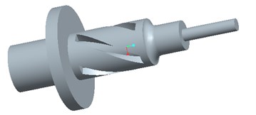
a) Three-dimensional model
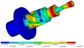
b) Displacement nephogram of horn
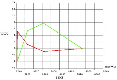
The proposed model was incorporated into the ANSYS commercial software package, and the modal analysis was performed to obtain the plot of displacements, as shown in Fig. 6(b). Modal simulation results showed that the resonant frequency was 34.914 kHz. As seen from the above figure, the milling tool end followed the radial direction and its displacement increased gradually, exhibiting typical torsional vibrations. Points at the milling tool edge in the -axis vicinity were identified and plotted as red dots in Fig. 7, while relative displacements of these points in and directions under different modes were obtained and exported into the time post-processing module, as shown in Fig. 8.
Fig. 7Position of extracted node
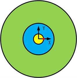
Fig. 8Displacement of node in Y and Z axis
To investigate the effects of spiral groove parameters, including helical angle (), groove quantity (), and groove width () on the ultrasonic vibration behavior, the (33) orthogonal tests were designed (see Table 2) with displacements of the milling tool end edge in and directions. Here the longitudinal-torsional ratio (LTR) of milling tools () was used as the evaluation indicator. In Table 2, , and were the average values of the sum of each test index, respectively. was variance.
Table 2Arrangement of orthonormal experiment on horn structure
Number | / ° | / mm | ||
1 | 30 | 2 | 2 | 0.31 |
2 | 30 | 4 | 3 | 0.23 |
3 | 30 | 6 | 4 | 0.21 |
4 | 45 | 4 | 4 | 0.28 |
5 | 45 | 6 | 2 | 0.65 |
6 | 45 | 2 | 3 | 0.78 |
7 | 60 | 6 | 3 | 4.76 |
8 | 60 | 2 | 4 | 1.02 |
9 | 60 | 4 | 2 | 1.33 |
0.75 | 2.11 | 2.29 | – | |
1.72 | 1.85 | 5.77 | – | |
7.12 | 5.62 | 1.51 | – | |
Range / | 6.37 | 3.77 | 4.26 | – |
Factors in the order | > > | |||
The optimized parameters are: 30°, 4, 6 mm.
The effect of on LTR was investigated for 4 and 6 mm (see Fig. 9(a)). As observed, LTR decreased and then increased with the helical angle and attained the minimal value at 30°. Therefore, the torsional oscillation component was maximized at 30° under the particular conditions.
The effect of the number of grooves on LTR was investigated at 30° and 6 mm (see Fig. 9(b)). As observed, LTR dropped with an increase in n, and exhibited a saturation at > 4. Hence, the torsional oscillation increased with . In practical cases, however, the material removal rate increased with at constant helical angle and groove width . In order to ensure a sufficient rigidity of the horn, was set to 4.
The impact of the groove width on LTR was investigated for the optimized values 4 and 30° (see Fig. 9(c)). As observed, has negligible effect on LTR. For practical considerations, was set to 6 mm, which ensured a sufficient horn rigidity.
Using the above parameters ( 4, 30°, and 6 mm), a spiral groove-type horn, as well as its joints, internal/external screw threads, and bores, were designed and manufactured.
Fig. 9Influence of parameters on the ratio of longitudinal and torsional
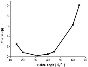
a) Helical angle
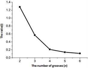
b) Number of grooves
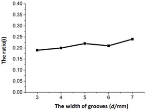
c) Groove width
4. Horn acoustic performance
In theoretical calculations and finite element modal analysis, the size and performance of horn and its connection to transducer and milling tool are assumed to be perfect. In practical cases, however, such factors as acoustic speed and energy loss at the joints/connections may induce deviations from the model calculations. Hence, the experimental verification of the developed horn was found expedient and was successfully realized in this study.
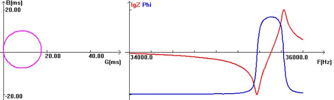
Fig. 10 shows the results obtained by impedance analyzer (BANRY PV70A by AM Solutions Co.) The experimental resonance frequency was 35.476 kHz, which differed from the numerical simulation result of 34.914 kHz by less than 2 %. The experimental dynamic resistance was 56.9 , and the quality factor was 835.
Fig. 10Impedance analysis of the horn
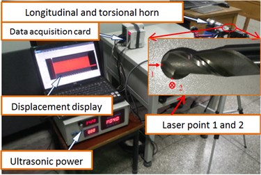
Insofar as horn output amplitude is the key indicator of the ultrasonic system performance, its accurate measurement and control is a pre-requisite for the horn testing.
The horn output amplitude was assessed using a displacement laser sensor (LK-G10 by KEYENCE Co. Ltd.). By employing the non-contact triangular measurement method, this sensor measures the object displacement via the reflected light motion. As shown in Fig. 11, the longitudinal and torsional vibration amplitudes of the rose cutter were obtained at Points 1 and 2, respectively.
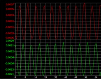
Fig. 12 shows different ultrasonic amplitudes obtained by tuning the ultrasonic generator frequency at the resonance frequency to control the output current.
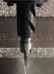
As observed, the longitudinal and torsional amplitude increased linearly with the current, and their ratio was maintained at 0.25, which was consistent with the simulation results obtained. The acoustic system was installed at the material processing center and connected to the ultrasonic generator. The vibration mode of milling tools was determined based on the ultrasonic cavitation. Fig. 13 shows the atomization testing. The spray was distributed with the ball center as the center. Therefore, it can be concluded that the tool exhibits a reliable vibration mode and meets the design requirements.
Fig. 11Measuring point of ultrasonic amplitude
a)
b)
Fig. 12Results of amplitude
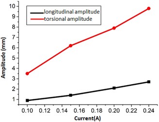
Fig. 13Atomization on edge of cutter
5. Conclusions
1) The amplification coefficient and vibration node of the horn were determined based on theoretical calculations and optimization based on the finite element simulation of the vibration system consisting of the horn and milling tools. Based on the size of step-like horns, longitudinal vibrations were converted into longitudinal-torsional coupled vibrations by developing spiral grooves on the horn straight part.
2) Orthogonal tests with parameters of spiral grooves as variables were designed, and the longitudinal-torsional ratio (LTR) of milling tool end under different conditions were obtained using ANSYS. The analysis of simulation revealed that LTR is controlled by such geometry factors as the helical angle , number of grooves , and groove width in the decreasing order.
3) Single-factor tests revealed that LTR dropped and then rose with the helical angle (with the minimal value attained at 30°), decreased with the number of grooves , and remained practically unchanged with the groove width variation.
4) The developed ultrasonic system with the optimized horn was tested at the material processing center and exhibited a stable performance as applied to longitudinal-torsional ultrasonic milling tools, which ensured an adequate ultrasonic cavitation processing.
References
-
Lin Zhongmao The Principle and Design of Ultrasonic Horn. Science Publishing Company, Beijing, 1987.
-
Asami T., Miura H. Study of ultrasonic machining by longitudinal-torsional vibration for processing brittle materials-observation of machining marks. Physics Procedia, Vol. 70, 2015, p. 118-121.
-
Shamoto E., Moriwaki T. Elliptical vibration cutting. Annuals of CIPR, Vol. 43, Issue 1, 1994, p. 35-38.
-
Zhou Guang-Ping Analysis of longitudinal-flexural and torsional-flexural complex-mode vibrations of ultrasonic vibration systems. Acta Acustica, Vol. 26, Issue 5, 2001, p. 438-439.
-
Wang Cuiying, Ya Gang, Wang Yue Dynamic analysis of the composite horn in ultrasonic shot peening. Machinery Design and Manufacture, Vol. 3, 2011, p. 216-218.
-
Al-Budairi H., Lucas M., Harkness P. A design approach for longitudinal-torsional ultrasonic transducers. Sensors and Actuators A-physical, Vol. 198, 2013, p. 99-106.
-
Liu Yao, Zhang Xiaolei Theoretical design of the composite horns. Journal of Electric Power, Vol. 27, Issue 5, 2012, p. 535-540.
-
Tang Jun, Zhao Bo Stability analysis of the separated longitudinal-torsional composite ultrasonic milling. Acta Armamentarii, Vol. 36, Issue 7, 2015, p. 1318-1325.
-
Cardoni A., Harkness P., Lucas M. Ultrasonic rock sampling using longitudinal-torsional vibrations. Physics Procedia, Vol. 3, 2010, p. 125-134.
-
Liang Zhaofeng, Lin Shuyu Stepped type ultrasonic horn with transitional section of cosine type. Journal of Shaanxi Normal University (Natural Science Edition), Vol. 31, Issue 4, 2003, p. 32-35.
-
Zhao Fuling, Feng Dongju, Guo Dongming Design of horn using four-end network method. Acta Acustica, Vol. 6, 2002, p. 554-558.
-
Yang J. J., Fang Z. D., Wei B. Y. Theoretical explanation of the “local resonance” in stepped acoustic horn based on four-end network method. Journal of Materials Processing Technology, Vol. 209, 2009, p. 3106-3110.
-
Roopa Rani M., Rudramoorthy R. Computational modeling and experimental studies of the dynamic performance of ultrasonic horn profiles used in plastic welding. Ultrasonics, Vol. 53, 2013, p. 763-772.
-
Feng Dongju, Zhao Fuling, Xu Zhanguo Modal analysis of ultrasonic horn using the Inventor software. Applied Acoustics, Vol. 29, Issue 1, 2010, p. 69-73.
-
Lai Yinan, Liu Xiangdong, Luo Jianwei Analyzing ultrasonic horn system by finite element method. Journal of Harbin University of Science and Technology, Vol. 6, Issue 1, 2001, p. 50-52.
-
Mori E., Itoh K., Imamura A. Analysis of a short column vibrator by apparent elasticity method and its application. Ultrasonic International Conference Proceedings, 1977, p. 262-267.
-
Ren Shuchu Multidimensional coupled vibration of piezoelectric vibrators (I) pure piezoelectric vibrators. Acta Acustica, Vol. 8, Issue 3, 1983, p. 147-158.
-
Ren Shuchu Multidimensional coupled vibration of piezoelectric vibrators (II) composite piezoelectric vibrators. Acta Acustica, Vol. 8, Issue 5, 1983, p. 272-279.
-
Lin Shuyu, Zhang Fucheng A study to the resonant frequency of ultrasonic horns with large rectangular cross-section. Acta Acustica, Vol. 17, Issue 6, 1992, p. 451-455.
-
Tang Jun, Zhao Bo A new longitudinal-torsional composite ultrasonic milling system with a single excitation. Journal of Vibration and Shock, Vol. 34, Issue 6, 2015, p. 57-71.
-
Nath C., Rahman M., Neo K. S. A study on ultrasonic elliptical vibration cutting of tungsten carbide. Journal of Materials Processing Technology, Vol. 209, 2009, p. 4459-4464.
-
Yuan Yiquan Ultrasonic Transducer. Nanjing University Press, Nanjing, 1992.
Cited by
About this article

This research was supported by National Natural Science Foundation of China (51675164 and 51475148).
