Abstract
With the developing of ultrasound technology and expending of it’s application scope, new requirements for the structure and the energy radiation of the transducer are presented. A reasonable design and manufacture of the transducer ensures that the energy can be transmitted with minimal loss. Based on the longitudinal vibration equation, a sandwich piezoelectric transducer which can be used in the field of precision machining, medical and other fields is designed and simulated in this paper. Different from the ordinary transducer, the front cover of this transducer is also a horn which can amplify the output amplitude compared to an equal section circular bar. ANSYS15.0 is used to calculate and analyze the transducer model with using HyperMesh (HM) software to generate the mesh to ensure the quality of the mesh. The finite element analysis software can calculate the transducer modal and harmonic response, and the results can be used to compare with theoretical design. The design frequency of the transducer is 20 kHz, the error between the simulation and the theoretical value is less than five percent, the result obtained by ANSYS is very close to the theoretical design.
1. Introduction
Transducer is one of the most important components in the ultrasonic vibration equipment, which plays an important role in the whole system. In 1917, French physicist Paul Langevin made a sandwich ultrasonic transducer with natural piezoelectric quartz to explore the submarine under the sea. Nowadays, ultrasonic vibration transducer is applied in many fields. In particular, the application in mechanical processing can improve the processing quality and the processing range. The application of ultrasonic vibration is different in different occasions, due to the output amplitude of the transducer is generally very small, it can be amplified by a horn to meet the needs of different amplitude.
There are many kinds of ultrasonic transducers. According to the material and energy conversion, ultrasonic transducer can be divided into piezoelectric, electric, electromagnetic, capacitive and other types. Piezoelectricity-based transducers are widely used, especially in ultrasonic sensors and actuators [1]. Piezoelectric transducers can complete the energy conversion and transmission though converting electrical signals into sound signals, or converting sound signals into electrical signals. Piezoelectric ceramic is the core component of piezoelectric transducer. According to the requirement of the transducer, the number of piezoelectric ceramics and the type of piezoelectric ceramics can be selected.
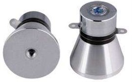
Fig. 1Ultrasonic transducer
2. Composition and design of piezoelectric transducer
2.1. Main components of the transducer
The piezoelectric transducer is mainly composed of a back cover, piezoelectric ceramics, electrode plates and a front cover. These components are connected together by a bolt, so the piezoelectric transducer is also known as sandwich piezoelectric transducer. The role of the front cover is to ensure that most of the energy generated by the transducer can be efficiently longitudinal radiation from the front face of the front cover to ensure the efficiency of vibration processing [2].
Front cover is generally made of light metal or alloy, titanium alloy is used in this paper. The main part of back cover is to guarantee the energy would be minimum lost to improve the forward radiation power of transducer. The most critical part of the piezoelectric transducers is piezoelectric materials, piezoelectric materials are the core of the application and development of sandwich piezoelectric transducers. Sandwich-type piezoelectric ultrasonic transducers primarily work in low-frequency ultrasonic ranges, requiring higher power, efficiency and vibration displacement. The vibration frequency and amplitude of each component must be tuned to that of the whole transducer, which creates a very demanding task [3].
2.2. Longitudinal vibration equation
The vibration equation and its solution are the theoretical basis of the transducer design.
Fig. 2Longitudinal vibration of a rod with arbitrary cross section.
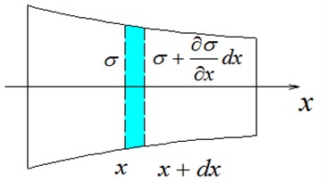
According to Newton’s law, the equation of longitudinal vibration of variable cross section bar can be determined:
In the case of simple harmonic vibration, Eq. (1) can be replaced by Eq. (2):
Eq. (2) is the one dimensional longitudinal vibration equation of thin section with variable cross section. is wave number and , is sound velocity.
When the cross section is uniform, , Eq. (2) can be changed to Eq. (3):
Through the general solution of the equation and the boundary conditions, the size of each part of the transducer can be calculated.
2.3. Design and calculation of transducer
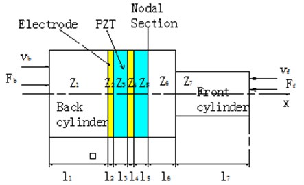
The component of the transducer is shown in Fig. 3. Different materials and shapes of back cover and front cover have different effects on the amplitude. The design object of the front cover which is a stepped cylinder is to get larger shape factor and magnification. Usually the back cover of the transducer is made of a heavy metal, and the front cover is made of a lighter weight metal which ensures that the energy generated by piezoelectric ceramics can be maximized to be passed to the front face. Commonly used front cover materials are aluminum alloy, titanium alloy. Aluminum alloy front cover can get high transmission efficiency, but due to the low mechanical strength, the front cover would be easily cracking and screwing slide wire. The comprehensive performance of titanium alloy is great, though the price is high and hard to process [4]. The front cover is titanium alloy and the back cover is 45 steel in this design.
Fig. 3Schematic of transducer
Because the electrode thickness is very small, it can be considered that 0, then get the frequency equation according to the solution of Eq. (3) and the boundary condition.
Frequency equation on the left side of the nodal section:
Frequency equation on the right side of the nodal section:
Based on the working frequency 20 kHz and two slices of PZT, a transducer is designed and calculated in this paper. The final design of the material and dimensions of the transducer parts are shown in Table 1.
Table 1Final design of the material and dimensions of the transducer parts
Component | Dimension parameter | ||
Diameter (mm) | Length (mm) | ||
Back cover | 50.00 | 36.74 | |
PZT | 50.00 | 5.00 | |
Front cover | Large End-face | 50.00 | 15.00 |
Small End-face | 35.00 | 54.40 | |
By changing the shape and size of the front and back covers and rationally designing the thickness of the piezoelectric ceramics, the optimized design of the piezoelectric ultrasonic transducer can be completed to meet the requirements of different working environments [5]. The amplitude can be further magnified by a horn which can eventually be applied to the tool or the workpiece.
3. Simulation of ultrasonic transducer
3.1. Finite element model of transducer
The transducer model is established according to the design dimension in the 3D software, then the finite element grid is divided in the HM which is a software with powerful capabilities in graphics processing [6]. A regular grid can guarantee the accuracy of the finite element simulation results, firstly, segment the model according to its features, this step is mainly to divide the horn, finally shown as Fig. 4(a). Then, divide grid in large end and small end face respectively, shown as Fig. 4(b), finally the high-quality grid of the whole model could be divided.
Fig. 4Meshing process
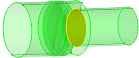
a)
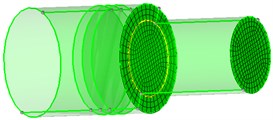
b)
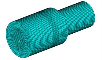
Import the data of finite element model into ANSYS and obtain the 3 order vibration modes in the set frequency range of the transducer by the modal analysis. The finite element model is shown as Fig. 5.
Fig. 5Grid model
3.2. Modal analysis
Designed structure can be model analysis using finite element analysis codes ANSYS, and the results will effectively estimate vibration specific of structure in order to optimize structure design [7]. Before the finite element analysis, it is necessary to define these parts, front cover and back cover material parameters are shown in Table 2. PZT needs to be defined dielectric constant, piezoelectric constant and elastic constant in ANSYS15.0.
Table 2Front cover and back cover material parameters of the designed structure
Material | Elasticity modulus / GPa | Density / (kgm-3) | Poisson’s ratio | Sound velocity / (ms-1) |
45 steel | 215 | 7800 | 0.28 | 5250 |
Ti alloy | 110 | 4500 | 0.34 | 4950 |
When the transducer finite element model is established, the corresponding constraints are applied to the model, transducer can be analyzed. The finite element analysis is based on the second type piezoelectric equation, that is, applying 0 voltage to the piezoelectric ceramic face to make it in short circuit. In this process, the Block Lanczos method is adopted, and the sparse matrix direct solver is used to extract the iteration of the model [8].
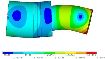
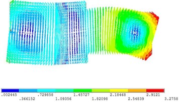
Fig. 6Vibration mode of frequency 19250 Hz
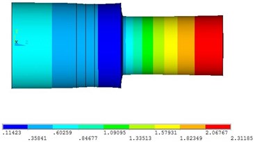
a)
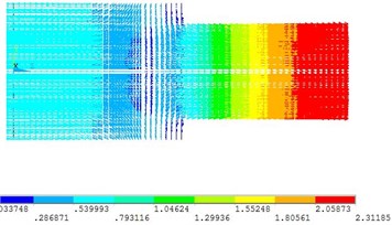
b)
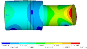
Fig. 7Vibration mode of frequency 21105 Hz
a)
b)
Fig. 8Vibration mode of frequency 21197 Hz
a)
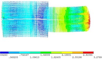
b)
Since the design frequency is 20 kHz, the frequency range selected in the analysis is 18-22 kHz. According to the result, the transducer in 1 modal is in the longitudinal vibration state, every particle’s displacement is in the axial direction and for 2 and 3 modals are in a bent state. At this point, there resonance frequency of transducer is 19250 Hz. Compared with the design data, the error is just about 3.75 % which proves the design is correct. In the first mode, the front-end face of the transducer is the maximum displacement surface, and the displacement of the section is zero.
3.3. Harmonic response analysis
Harmonic response analysis is mainly used to analyze whether the ultrasonic vibration system tool resonates at the natural frequency of the system, and in the resonance conditions, the maximum amplitude of the tool can meet the actual processing needs. Thus, judging the entire ultrasound vibration system design is reasonable or not [9]. Based on the electric-structure coupling model, harmonic response simulation is used in the ultrasonic transducer, the modal superposition method is used for the harmonic response analysis [10]. Harmonic response analysis for the transducer should be taken to calculate the amplification coefficient. Apply 300 V alternating voltage on the face of PZT and the harmonic response curves as shown in Fig. 9, Fig. 10. Fig. 9 shows the center point displacement of the transducer’s front-end face and Fig. 10 shows the center point displacement of the transducer’s back face.
Fig. 9Amplitude frequency response curve of transducer front end-face
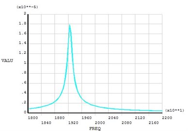
Fig. 10Amplitude frequency response curve of transducer back end-face
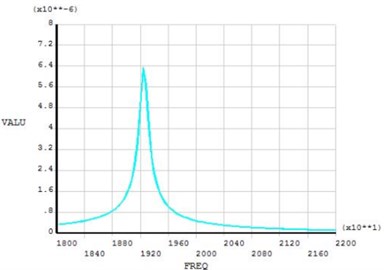
When the frequency is 19250 Hz, the harmonic response amplitude of the front and back end of the transducer reaches the maximum value. From the curves, the longitudinal amplitude of front face is 18 μm and the amplitude of back face is 6.4 μm under the excitation of 19250 Hz. The amplitude of front face is 2.8 times of back face.
4. Applications
In practical applications, the corresponding tools can be added to the front end of the horn according to the requirements. Fig. 11(a) shows the application of transducer in the field of mechanical processing, the piezoelectric transducer transforms the electric energy into vibration and the vibration can be used to process hard or brittle materials to achieve good results. Fig. 11(b) shows the application of piezoelectric transducer in the medical field; the phacoemulsification handle can be used for cataract surgery with many excellent effects.
Fig. 11Application of transducer
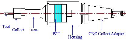
a) Ultrasonic vibration spindle
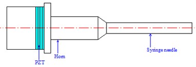
b) Phacoemulsification handle
5. Conclusions
Based on the longitudinal vibration equation, the transducer is designed and analyzed by ANSYS in this paper, Through the simulation analysis of the modal, natural frequency and vibration mode of the transducer is obtained. Transducer would be longitudinal vibration in 19250 Hz, which was very close to the design. The finite element software plays an important role in structural design, the design structure can be optimized directly. The combination of finite element software and theoretical design has a guiding significance for practical application.
References
-
Piao Chunguang, Jin O. K. Vibration characteristics of an ultrasonic transducer of two piezoelectric discs. Ultrasonics, Vol. 74, 2017, p. 72-80.
-
Feng Xianglin Design and simulation of 1/2 wavelength sandwich piezoelectric ceramic ultrasonic transducer. Dual Use Technologies and Products, 2012.
-
Parrini L. New technology for the design of advanced ultrasonic transducers for high-power applications. Ultrasonics, Vol. 41, Issue 4, 2003, p. 261-269.
-
Zhongmao Lin The Principle and Design of Ultrasonic Horn. Science Press, Beijing, 1985.
-
Hossack J. A., Auld B. A. Improving the characteristics of a transducer using multiple piezoelectric layers. IEEE Transactions on Ultrasonics Ferroelectrics and Frequency Control, Vol. 40, Issue 2, 1993, p. 131-139.
-
Frijlink M. E., Torp H. Simulation of acoustic fields from arbitrary transducer stacks using a FEM transducer model and nonlinear wave propagation. Ultrasonics Symposium, 2009, p. 2340-2343.
-
Yang Kang, Han T. The application of Ansys in model analysis. Journal of Jiamusi University, 2005, p. 103-108.
-
Li Xun, Zhang D. Ultrasonic elliptical vibration transducer driven by single actuator and its application in precision cutting. Journal of Materials Processing Technology, Vol. 180, Issues 1-3, 2006, p. 91-95.
-
Li Denghua The Analysis of cymbal transducer’s harmonic response based on 1-3 piezocomposite. Ferroelectrics, Vol. 405, 2010, p. 161-167.
-
Fan X., Ma S., Zhang X., et al. Simulation analysis of piezoelectric ceramic chip PZT based on Ansys. Piezoelectrics and Acoustooptics, Vol. 36, Issue 3, 2014, p. 416-420.
Cited by
About this article

