Abstract
The authors are developing multi degree of freedom micro spherical ultrasonic motor using wire stator for vascular endoscope. Spherical ultrasonic motor with 20 times model is used to confirm the driving characteristics as experimental equipment. Wire stator is designed by assuming the introduction to a vascular endoscope and transient response analysis is performed by the finite element method compared with 20 times model. In this study, the authors improve new support structure on waveguide and investigate new influence of the attenuation of the traveling wave transmitted on the wire stator by analyzing and changing the condition of the model. In the future, the authors will measure the amplitude of the wire stator by experiment and verify the accuracy of the simulation.
Highlights
- Spherical ultrasonic motor
- Wire stator
- Support structure
- Finite element method
- Transient response analysis
1. Introduction
Coronary artery disease caused by arteriosclerosis is a major causes of death as heart disease in world. Vascular endoscope can be used to observe the coronary artery, which has been developing fast such as enabling a visualization of coronary artery. State of diseased parts in blood vessel can be captured with naked eye by vascular endoscope and information can be obtained as three-dimensional color image. However, since vascular endoscope is very small, it is impossible to mount a multi degree of freedom actuator into the camera. For this reason, the lens cannot be driven in any direction, and it is difficult to obtain a precise image about the lesion on the inner wall of the blood vessel. To solve this problem, the authors are developing multi degree of freedom micro spherical ultrasonic motor using wire stator for vascular endoscope, which can drive camera in any direction.
In previous study, spherical ultrasonic motor with 20 times model is used to confirm the driving characteristics as experimental equipment. Wire stator is designed by assuming the introduction to a vascular endoscope and transient response analysis is performed by the finite element method compared with 20 times model. In addition, influence of the attenuation of the ultrasonic vibration transmitted on the wire stator with or without support structure by analyzing and changing the condition of the model is investigated. In this study, new support structures on waveguide are improved and new influence of attenuation is investigated by improved support structure and different vibration direction.
2. Spherical ultrasonic motor using wire stator
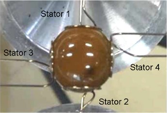
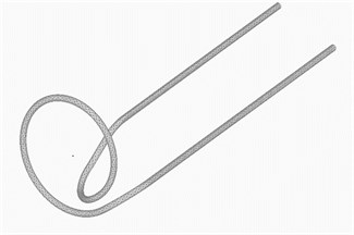
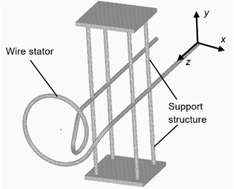
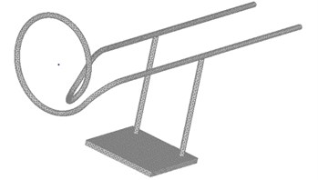
The schematic diagram of spherical ultrasonic motor using wire stator is shown in Fig. 1. The motor is composed of a Langevin transducer as ultrasonic vibration source, a wire stator for transmitting ultrasonic vibration, and a spherical rotor rotated by vibration. In previous study, polycarbonate is used for the spherical rotor and SUS304 is used for the wire stator as the material of the motor. One-axis spherical ultrasonic motor is shown in Fig. 2. When ultrasonic vibration is applied to one end of the wire stator, a traveling wave is generated toward the other end, and the surface of the wire stator performs elliptical motion in the direction opposite to the traveling wave. The spherical rotor receives frictional force at the contact surface with the wire stator due to elliptical motion and rotates in the direction opposite to the traveling wave. By making two pairs of wire stators to hold the spherical rotor, it becomes two-axis drive as shown in Fig. 3. In the wire stators, there are two waveguides inside and outside of coil. The direction of the traveling wave can be changed by the connection method of the Langevin transducer, and the rotation direction of the rotor can be reversed. In addition, by simultaneously connecting both waveguides, it is possible to generate a standing wave that does not affect the driving. The main feature of the spherical ultrasonic motor using wire stator is that the number of parts is small, the structure is simple, and it is suitable for miniaturization.
Fig. 1Schematic diagram of spherical ultrasonic motor
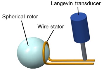
Fig. 2One-axis spherical ultrasonic motor using wire stator
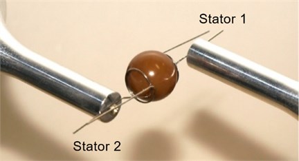
Fig. 3Two-axis spherical ultrasonic motor using wire stator
3. Analysis of equivalent model
3.1. Analysis of actual size wire stator
The wire stator used in previous study is approximately 20 times as large as the size of the vascular endoscope. The waveguide, which is the part of transmitting vibration of the wire stator, is 30 mm. In this study, an actual size wire stator with the assuming introduction to a vascular endoscope is designed as shown in Fig. 4. The dimensions of actual size wire stator model and 20 times model used for experiment in previous study are shown in Table 1. A transient response analysis for these two wire stator models is performed by the finite element method and the output is compared. The finite element model of actual size wire stator is shown in Fig. 5. The finite element model of experiment wire stator used in previous study is shown in Fig. 6. In these two models, a displacement input is made to the node at one end of the wire stator in the conditions as shown in Table 2, and the displacement of the node of the coil part, which is the contact part with the spherical rotor, is carried out. In addition, Femap with NX Nastran is used for finite element analysis.
Fig. 4Actual size wire stator
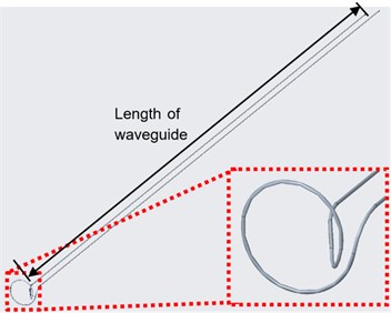
Table 1Size of wire stator
Experiment model | Actual size model | |
Wire diameter [mm] | 0.5 | 0.03 |
Outside diameter of wire [mm] | 10 | 0.5 |
Length of waveguide [mm] | 30 | |
Table 2Simulation conditions
Experiment model | Actual size model | |
Input waveform | Sine pulse | |
Frequency [kHz] | 24.6 | |
Amplitude [m] | 0.01 | 5×10⁻⁴ |
Simulation time [s] | 0.03 | |
Sampling time [s] | 5.0813×10⁻⁶ | |
Fig. 5Analysis model of actual size wire stator
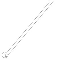
Fig. 6Analysis model of experiment wire stator
3.2. Analysis result of actual size wire stator
The displacement in the coil part of wire stator is obtained by analysis from 0.0025 s to 0.003 s. The result of the assuming dimension of the introduction to a vascular endoscope is shown in Fig. 7. The result of the 20 times model used for experiment is shown in Fig. 8. Each waveform is sine wave, and there is no phase difference. As a result, it is considered that the evaluation of the 20 times model can be applied to the actual size wire stator.
4. Analysis model of wire stator with support structure on waveguide
4.1. Analysis of wire stator with support structure on waveguide
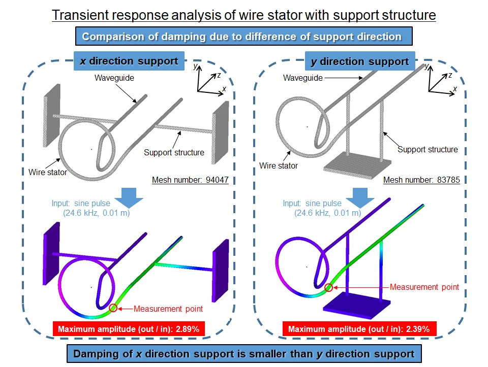
Since the length of vascular endoscope catheter is approximately 2 m, it is necessary to support the waveguide when a spherical ultrasonic motor is introduced. A support structure is added to the model of the wire stator used in previous study as shown in Fig. 9. Transient response analysis is performed by the finite element method. The influence of attenuation by adding support structure is investigated. The material of the support structure is SUS304, which is similar to the material of wire stator. The diameter of the rod-like part is the same as the wire stator, which is 0.5 mm. The displacement input is performed in the conditions shown in Table 2. As shown in Fig. 9, the direction perpendicular to the support rod and the waveguide is defined as direction, and the direction parallel to the support rod is defined as direction, and the traveling direction of the traveling wave is defined as direction. The direction displacement in the node of the coil part is carried out when the displacement input is performed in two directions of and .
Fig. 7Amplitude of coil part (actual size model)
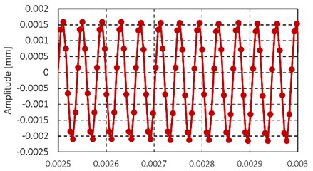
Fig. 8Amplitude of coil part (experiment model)
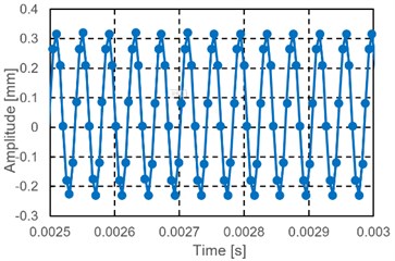
Fig. 9Analysis model of wire stator with support structure
4.2. Analysis result of wire stator with support structure on waveguide
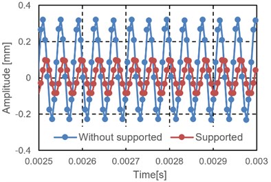
The analysis results from 0.0025 s to 0.003 s for the displacement input in and direction are shown in Fig. 10 and Fig. 11. As shown in Fig. 10, the amplitude in the coil part of the wire stator with support structure on waveguide is 0.058 mm, and the amplitude in the coil part of the wire stator without support structure on waveguide is 0.081 mm. From this result, when the displacement input is performed in the direction perpendicular to the support rod, the influence on the amplitude of the support appears as a decrease of 27.3 %. Moreover, as shown in Fig. 11, the amplitude in the coil part of the stator with support structure on waveguide is 0.091 mm and the amplitude in the coil part of the stator without support structure on waveguide is 0.27 mm. From this result, when the displacement input is made in the direction parallel to the support rod, the influence on the amplitude of the support appears as a decrease of 66.8 %. Comparing these two results, the amplitude is decreased by 39.5 % when displacement input is performed in direction rather than in direction. The reason for this result is that excitation in direction is difficult because the support structure is not easily bent due to the structure and the amplitude is suppressed by direct support. The amplitude in the coil part is greatly different by the displacement input direction. Attention to the model without the support structure, it is found that the displacement output in direction input is approximately 3 times larger than in direction input without support structure. This is due to the 90° bending structure when the wire stator moves from the waveguide to the coil part. By this structure, the amplitude of the traveling wave is 90° and the amplitude in direction is the amplitude in direction, and the amplitude in direction will be the amplitude of radial direction of the coil part.
Fig. 10Amplitude of coil part (x direction input)
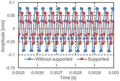
Fig. 11Amplitude of coil part (y direction input)
From the above, it can be confirmed that the vibration transmitted to the coil part varies depending on the direction of the displacement input made to the tip with the same support structure. In addition, more attenuating appears as the traveling wave close to parallel to the support structure. It can be confirmed that the output changed by the direction of displacement input to the tip whether or not there is the support structure.
5. Improvement of wire stator model with support structure on waveguide
5.1. Analysis model of improved wire stator with support structure on waveguide
It is clarified that the amplitude in direction is greatly decreased with the support structure added in Section 4.2. Based on the result, new support structure is designed, which can hardly inhibit the amplitude in direction.
The model of improved support structure on waveguide is shown in Fig. 12. In Section 4.2, it is considered that the vibration in the perpendicular direction to the pillar part of the support structure is not easy to be attenuated, so that the support structure is added in the perpendicular direction to direction, that is direction. In addition, in order to arrange the conditions other than the support direction, the model is made from a partial pillar of the support structure used in Section 4. This is the model added the support structure in direction as shown in Fig. 13. In the two models, the displacement input is performed in the conditions shown in Table 2 and a transient response analysis is performed. The input direction is only in direction.
Fig. 12Improved wire stator model (x direction support)
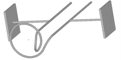
Fig. 13Improved wire stator model (y direction support)
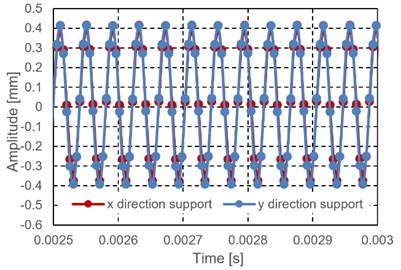
5.2. Analysis result of improved wire stator model with support structure on waveguide
In the two models, the analysis results are from 0.0025 s to 0.003 s shown in Fig. 14 when the displacement input is made in direction. In the improved fixing method, there is almost no difference in the attenuation due to the difference in support direction as shown in Fig. 14. As a result, it is considered that the difference of the amplitude attenuation in the displacement input direction in Section 4.2 is not the influence of the support direction but the rigidity of the whole structure. From the above, the improved support structure supports the waveguide from any direction, and the improved support structure can hardly inhibit the vibration, which is suitable.
Fig. 14Amplitude of coil part (x and y direction support)
6. Conclusions
In this study, the authors have concluded as follows.
1) The authors have designed and made an ultrasonic motor using wire stator for experiment and designed the wire stator by assuming the introduction to a vascular endoscope.
2) The authors have made transient response performed by the finite element method for the model of the wire stator with improved support structure, and it is possible to clarify that attenuation is affected by improved support structure and different vibration direction.
References
-
Mizuno K. Angioscopic evaluation of coronary plaque and thrombus. Japanese Journal of Thrombosis and Hemostasis, Vol. 8, Issue 3, 1997, p. 236-241.
-
Takesue N., et al. Position control methods of spherical ultrasonic motor. Proceedings of IEEE/RSJ International Conference on Intelligent Robots and Systems, 2010, p. 3061-3066.
-
Sashida T., Kenjo T. An Introduction to Ultrasonic Motors. Oxford University Press, Oxford, 1993.
-
Purwanto E., Toyama S. Control method of a spherical ultrasonic motor. Proceedings of IEEE/ASME International Conference on Advanced Intelligent Mechatronics, 2003, p. 1321-1326.
-
Mashimo T., Awaga K., Toyama S. Development of a spherical ultrasonic motor with an attitude sensing system using optical fibers. Proceedings of IEEE International Conference on Robotics and Automation, 2007, p. 4466-4471.
-
Yano T., Maeno T. Spherical motor. Journal of the Robotics Society of Japan, Vol. 21, Issue 7, 2003, p. 740-743.
About this article

