Abstract
The purpose of this study is to develop a miniature motor for directional adjustment of a vascular endoscopic camera. Spherical ultrasonic motor not affected by magnetic fields is used in the miniature motor. The characteristic of spherical ultrasonic motor is that one motor has multi degree of freedom in rotational direction. Wire is used as stator to realize miniaturization of the motor, so it is called miniature spherical ultrasonic motor using wire stators. Firstly, the pressing force between a stator and a spherical rotor is discussed, which is important for developing a miniature spherical ultrasonic motor using wire stators. As a result, it can be clarified that there is an optimum value for the pressing force. Secondly, the starting torque is investigated, which is one characteristic of the miniature spherical ultrasonic motor using wire stators. The relationship between the frequency and amplitude of the applied AC voltage and the starting torque is clarified. Finally, the control method of the rotational direction of a miniature spherical ultrasonic motor using wire stators is discussed. A PWM control method is proposed to control the rotational direction of an ultrasonic motor. In this PWM control, traveling wave and standing wave generated on a wire stator are used. Experimental results show that the proposed method is effective.
1. Introduction
The ischemic heart disease caused by arteriosclerosis occupies higher cause of death in the world. Arteriosclerosis is caused by stenosis of the vascular lumen due to the hardening of blood vessels and the accumulation of plaque by aging. Angiography and intravascular ultrasound have been used for the examination and observation of the blood vessel. Vascular endoscope [1-4] technically improved has been used in the medical field in the 1980s. For comparison with angiography and intravascular ultrasound, it can be indicated that vascular endoscope is effective [5-7]. As the advantages of the vascular endoscope, there are three dimensional blood vessel surface, full color, and high resolution. As the disadvantage of the vascular endoscope, it can be mentioned that it is difficult to intercept blood flow and observe the blood vessel wall. In addition, it is difficult to photograph the lesion of the wall in the center of the image in the existing vascular endoscopic camera in the observation of the blood vessel lumen. In order to carry out the correct diagnosis, it can be desired to photograph the lesion in the center of the image.
In this study, the purpose is to develop a miniature motor for directional adjustment of a vascular endoscopic camera. Spherical ultrasonic motor [8-10] not affected by magnetic fields is used in the miniature motor. The characteristic of spherical ultrasonic motor is that one motor has multi degree of freedom in rotational direction. Wire is used as stator to realize miniaturization of the motor, so it is called miniature spherical ultrasonic motor using wire stators. The purpose of this study is to obtain the basic characteristics of a miniature spherical ultrasonic motor using selected wire stators. It can be also proposed that the PWM control method applied to control the rotational direction is effective after validation.
2. Spherical ultrasonic motor using wire stator
2.1. Ultrasonic motor
Ultrasonic motor is an actuator driven by mechanical vibration in ultrasonic field. The ultrasonic motor is composed of a rotor and a stator, and piezoelectric elements are attached to the metal elastic body in the stator. According to the driving principle of the ultrasonic motor, it can be driven by the contact between the stator vibration surface and the part of the rotor, so rotational motion can be realized by simple mechanism. Therefore, it is suitable for miniaturization and lightening compared with other motors such as DC motor.
In this study, the spherical ultrasonic motor using wire stators is a kind of the traveling wave type ultrasonic motor. In the traveling wave type ultrasonic motor, the traveling wave is generated when AC voltage with 90° phase difference is applied to the piezoelectric elements of the stator. By this traveling wave, the point on the metal elastic surface performs elliptical motion. By pressing the rotor to the stator, an elliptical motion is transmitted to the rotor by friction and the driving force is obtained. This elliptical motion is opposite to the traveling direction of the traveling wave, so the rotor moves in the direction opposite to the traveling direction of the traveling wave.
2.2. Spherical ultrasonic motor
The spherical ultrasonic motor is composed of one rotor and three stators as shown in Fig. 1. The rotor is spherical and the material is resin. The stator has an annular shape with piezoelectric elements attached to a metal elastic body with comb teeth. The tiny vibration using electrostriction phenomenon of piezoelectric element is obtained by applying AC voltage in ultrasonic field to piezoelectric element, and the traveling wave propagates in the vibration medium on the stator surface. This elliptical motion is transmitted to the spherical rotor by friction.
Features of a spherical ultrasonic motor are listed below. The collision operation between the rotor and the stator is continuous, so the spherical ultrasonic motor has little abrasion compared with other ultrasonic motors. Switching between forward rotation and reverse rotation can be made by changing the traveling direction of the traveling wave. In addition, the rotor and the stator are always pressurized by a leaf spring, so the force acting between the rotor and the stator is kept constant at the time of the stationary state or low rotation of the rotor. Therefore, there is a holding force without the braking mechanism in the stationary state and without the power supply, and large torque is obtained at low rotation.
2.3. Spherical ultrasonic motor using wire stators
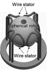
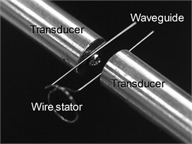
The spherical ultrasonic motor using wire stators developed in this study uses a wire as a stator instead of an annular stator of a spherical ultrasonic motor described in Section 2.2. The schematic diagram of spherical ultrasonic motor using wire stators is shown in Fig. 2. The spherical ultrasonic motor using wire stator is composed of one spherical rotor, four wire stator with waveguides, and an ultrasonic vibration source.
The spherical ultrasonic motor using wire stator has spiral shape, and the wire has a function as a stator. The driving principle is similar to the coil type ultrasonic motor [11]. The traveling wave is generated by adding ultrasonic vibration to the integrated waveguide and the wire stator. Elliptical motion of a wire stator surface rotates the spherical rotor.
Four wire stators are arranged in two sets, and each set of wire stators is arranged to face each other across a spherical rotor. The axes connecting the center of the stators face to face are respectively defined as axis and axis. The force is respectively generated by rotating a spherical rotor around each axis in two sets of wire stators. Two degree of freedom of rotation is obtained by the synthesis of rotational vector. The degree of freedom required for driving the vascular endoscopic camera is two degree of freedom.
Fig. 1Photograph of spherical ultrasonic motor
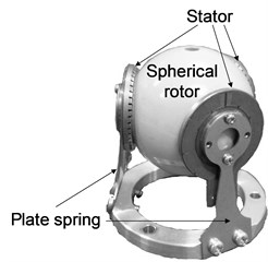
Fig. 2Schematic diagram of spherical ultrasonic motor using wire stators
2.4. Shape of wire stator
In the previous study [12], two types of ring and spiral types have been proposed as stator shapes of spherical ultrasonic motor using wire stators as shown in Fig. 3. The ring type stator shown in Fig. 3(a) has a structure in which the waveguide is extended from a ring type wire. As the advantage of ring type, it can be miniaturized for its simple structure. In addition, it is also advantageous that the non-uniformity of the contact surface can hardly occur as the a spherical rotor is supported by one loop. On the other hand, as the disadvantage of ring shape, the driving force is declined by the decrease of the contact surface.
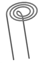
Fig. 3Schematic diagram of wire stator
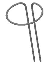
a) Ring type
b) Spiral type
The spiral type stator shown in Fig. 3(b) has a structure in which the waveguide is extended from the spiral wire. As the advantage of spiral type, the loop supporting the spherical rotor increases, so the contact surface increases and the driving force is improved. In addition, one end of the waveguide is located at the center of the stator, so it is also advantageous that the pressing force can be applied. On the other hand, the spiral is not suitable for miniaturization due to the large numbers of loops.
In consideration of the above, the spiral type stator approximately one spiral is used in this study as shown in Fig. 4. The wire stator used in the experiment is shown in Fig. 4(a). The wire stator is stainless steel (SUS304), the maximum diameter is 10 mm, and the wire diameter is 0.5 mm. The length of the waveguide is 30 mm. Asymmetry of shape is considered, and two types of left and right spirals are designed. In addition, there are two waveguides in the outside and inside wire stators. By changing the waveguide connected with the vibration source, the direction of traveling wave changes, and the rotational direction of the spherical rotor can be reversed. In this study, the case where the vibration source is connected to the outside waveguide is forward rotation as shown in Fig. 4(b), and the case where the vibration source is connected to the inside waveguide is reverse rotation as shown in Fig. 4(a).
Fig. 4Wire stator of single spiral
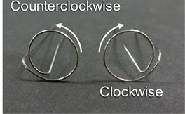
a) Winding pattern
b) Connection of forward rotation
c) Connection of reverse rotation
3. Pressing force of spherical ultrasonic motor using wire stators
3.1. Relationship between pressing force and pressing distance
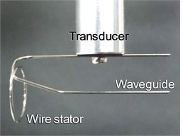
The experimental equipment shown in Fig. 5 is prepared to investigate the relationship between the pressing force and the pressing distance. The experimental equipment is composed of an X stage and a spherical ultrasonic motor. A load cell is attached to the X stage. The spherical ultrasonic motor is composed of one spherical rotor, one wire stator, and one vibration source. The waveguide of wire stator is located at the tip of a fixed vibration source.
Fig. 5Experimental equipment of pressing force measurement
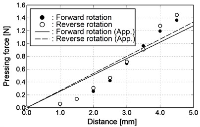
One part of the spherical rotor is in contact with the wire stator, and the other part is in contact with the X stage. The X stage is pressed against the spherical rotor while measuring the distance using a micrometer, and the output voltage of the load cell for the pressing distance is recorded. The relationship between the pressing force and the pressing distance in the case where the wire stator of forward rotation connection and reverse rotation connection is used as shown in Fig. 6. Large difference due to the connection state cannot be seen, so the pressing distance is converted to the pressing force using the following approximate straight line:
where is the pressing force, and is the pressing distance.
Fig. 6Relationship between pressing distance and pressing force
3.2. Experimental method on pressing force and rotational speed
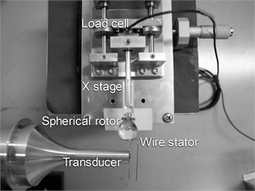
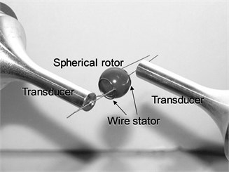
The experimental equipment shown in Fig. 7 is used to investigate the optimum pressing force. The experimental equipment is composed of a spherical ultrasonic motor, an stage, a waveform generator (WF1974, NF Corporation), and an amplifier (BA4825, NF Corporation). The spherical ultrasonic motor is one axis, which is composed of one spherical rotor, two wire stators, and two Langevin transducers of vibration source. The material of the spherical rotor is polycarbonate and the diameter is 15 mm. The waveguide of wire stator is located at the tip of the Langevin transducer. One part of the Langevin transducer is fixed, and the other part is located on the stage so that the position can be changed.
Fig. 7Experimental equipment of rotational speed measurement
The AC voltage with amplitude and frequency control is sent from the waveform generator to the amplifier, and the voltage is applied to the Langevin transducer vibrating the wire stator. The vibration frequency is 24.6 kHz equal to the resonant frequency of the Langevin transducer. In addition, the position where the spherical rotor contacts the wire stator (pressing force = 0 N) is assumed to be 0 mm as the reference point of the pressing position. The micrometer of the stage is applied to move one wire stator in parallel at 0.1 mm intervals, and the rotational speed is measured with increasing pressing force. The measuring range of the rotational speed of the spherical rotor, which can be held properly by the wire stator, is from 2.0 mm to 4.0 mm. Through the above operation, the amplitude of the AC voltage is changed from 10 Vp-p to 70 Vp-p at 10 Vp-p intervals, and forward rotation and reverse rotation are respectively carried out. The pressing distance is converted to the pressing force by the approximate straight line from Eq. (1). The rotational speed is obtained from the video taken by the video camera.
3.3. Experimental result on pressing force and rotational speed
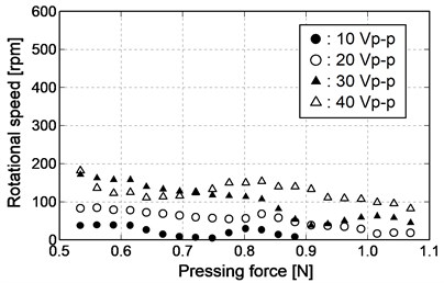
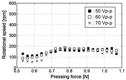
The measuring results of the rotational speed with respect to the pressing force in the case where the method of mounting the wire stator is forward rotation are shown in Fig. 8. The number of measuring points is small in the case where the amplitude of AC voltage is 10 Vp-p, as the rotation stops before pressing to the specified position. As shown in Fig. 8(a), the rotational speed increases uniformly when the amplitude of AC voltage is increased from 10 Vp-p to 40 Vp-p. In addition, the rotational speed decreases with increasing the pressing force. As shown in Fig. 8(b), the rotational speed decreases slightly with the pressing force in the range of 0.7 N or less when the amplitude of AC voltage is increased from 50 Vp-p to 70 Vp-p. However, the rotational speed increases with the pressing force in the range of 0.7 N or more. In addition, the rotational speed decreases with increasing pressing force.
Fig. 8Relationship between pressing force and rotational speed (forward rotation)
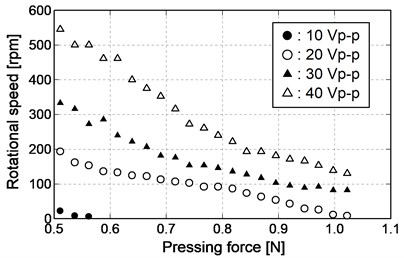
a) 10 Vp-p-40 Vp-p
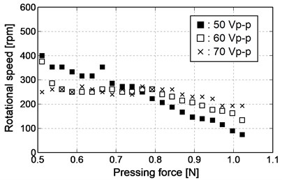
b) 50 Vp-p-70 Vp-p
Fig. 9Relationship between pressing force and rotational speed (reverse rotation)
a) 10 Vp-p-40 Vp-p
b) 50 Vp-p-70 Vp-p
On the other hand, the measuring results of the rotational speed with respect to the pressing force in the case where the method of mounting the wire stator is reverse rotation are shown in Fig. 9. The number of measuring points is small in the case where the amplitude of AC voltage is 10 Vp-p, as the rotation stops before pressing to the specified position. As shown in Fig. 9(a), the rotational speed increases uniformly when the amplitude of AC voltage is increased from 10 Vp-p to 40 Vp-p. In addition, the rotational speed tends to decrease, but it tends to increase in the middle when the pressing force is increased. As shown in Fig. 9(b), the rotational speed decreases slightly with the pressing force in the range of 0.7 N or less when the amplitude of AC voltage is increased from 50 Vp-p to 70 Vp-p. However, the change of the rotational speed is small with the pressing force in the range of 0.7 N or more. In addition, the rotational speed tends to decrease first and then increase when the pressing force is increased in the range of 0.7 N or less. However, the fluctuating of the rotational speed decreases when the pressing force is increased in the range of 0.7 N or more.
Comparing with Fig. 8 and Fig. 9, it can be seen that the rotational number and tendency are different between forward rotation and reverse rotation. It can be considered that the difference of the rotational number and tendency is caused by the fixed position of the stator with waveguide. The first contact is inside of the spiral when the wire stator is made to approach the spherical rotor. In the case of forward rotation in which the outside waveguide is connected, the pressing force is transmitted uniformly to the inside in order to press the spherical rotor from the outside of the stator. On the other hand, in the case of reverse rotation in which the inside waveguide is connected, the pressing force is transmitted non-uniformly to the outside in order to press the spherical rotor from the inside of the stator. Therefore, it can be considered that the distribution of the friction force transmitted from the wire stator to the spherical rotor is different between forward rotation and revere rotation. Then, both waveguides are used when the wire stator is pressed against the spherical rotor.
In this study, it can be assumed that a miniature spherical ultrasonic motor is used for the vascular endoscope. The actual waveguide is longer than the experimental equipment and the attenuation of the traveling wave is expected, so the output can be as large as possible. Therefore, the amplitude of the voltage is approximately 40 Vp-p in forward rotation, and it is suitable when the pressing force is approximately 0.5 N. The amplitude of the voltage is approximately 60 Vp-p in the case of reverse rotation, and it is suitable when the pressing force is approximately from 0.7 N to 0.8 N.
4. Starting torque of spherical ultrasonic motor
4.1. Measuring method of starting torque
In order to measure the starting torque, the weights are attached to the spherical rotor of the experimental equipment through a string as shown in Fig. 7. The Langevin transducer with resonant frequency of 24.6 kHz is used as the ultrasonic vibration source.
In this experiment, the starting torque of the spherical rotor is respectively measured for both forward rotation and reverse rotation by changing the frequency and amplitude of the applied AC voltage. The load of the weights is mounted to the motor without driving from 1000 mg, the load is reduced by 10 mg, and the starting torque is calculated from the load when the spherical rotor begins to rotate. Firstly, the applied voltage of the Langevin transducer is fixed to 40 Vp-p, and the starting torque is measured by changing the applied frequency from the resonant frequency by 0.005 kHz. Secondly, the applied frequency of the Langevin transducer is fixed to 24.6 kHz, which is the same as the resonant frequency, and the starting torque is measured by changing the applied voltage from 10 Vp-p to 70 Vp-p by 10 Vp-p.
4.2. Experimental result on starting torque
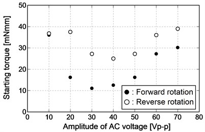
The starting torque is shown in Fig. 10 when the frequency is changed. The starting torque is maximum regardless of the rotational direction when the applied frequency is the resonant frequency of the Langevin transducer. In addition, the starting torque decreases when the applied frequency leaves the resonant frequency. The starting torque is shown in Fig. 11 when the amplitude of the voltage is varied. The starting torque is high when the amplitude of the voltage is small, and the starting torque decreases from 20 Vp-p in forward rotation and from 30 Vp-p in reverse rotation. However, after the starting torque decreases, the starting torque becomes higher again as the amplitude of the voltage increases.
The influence of the friction force is considered as the cause of the tendency as shown in Fig. 11. The vibration at the surface of the wire stator decreases when the amplitude of the voltage is small. It can be considered that the static friction force between the wire stator and the spherical rotor acts and the starting torque increases. On the other hand, the vibration at the surface of the wire stator becomes large when the amplitude of the voltage is large. It can be considered that the dynamic friction force between the wire stator and the spherical rotor acts and the starting torque decreases. However, the reason for the starting torque increasing again after decreasing is that the vibration at the surface of the wire stator becomes larger when the amplitude of the voltage increases in the range of the dynamic friction force and the cause of the increase of the friction force is considered to be the increase of the contact part with the spherical rotor.
Fig. 10Relationship between frequency of AC voltage and starting torque
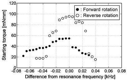
Fig. 11Relationship between amplitude of AC voltage and starting torque
5. PWM control of rotational direction
5.1. Application of PWM control on spherical ultrasonic motor
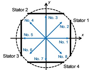
Two degree of freedom drive of spherical ultrasonic motor using wire stators is made by synthesizing the driving forces of two sets of axes when the waveguide is connected vertically to the vibration source. In the previous study [12], the rotational direction is controlled in eight directions by synthesizing the driving forces of forward rotation and reverse rotation with the same size. The rotational direction of the eight directions by synthesizing the driving forces is shown in Fig. 12 and Table 1. In this study, a control method to obtain the rotational direction in all directions is proposed. With synthesizing the driving forces of two sets of axes, the rotational direction changes according to the difference of the driving forces when the difference is given to the driving forces. A method to increase or decrease the amplitude of the traveling wave generated on the one axis is considered as a method of giving the difference to the driving forces. However, the friction force between the wire stator and the spherical rotor increases with the smaller amplitude and prevents driving, so it is not suitable for the control of the rotational direction. In this study, the PWM control method used in the control of an electromagnetic motor is applied to an ultrasonic motor. Using this method, it is possible to change the driving force transmitted to the spherical rotor without changing the friction force between the wire stator and the spherical rotor.
Fig. 12Schematic diagram of rotational direction
PWM control used in an electromagnetic motor is a method of controlling the output of an electromagnetic motor by switching the constant voltage on and off. A constant period of on and off of a pulse sequence is made from the input of a constant voltage, and an arbitrary voltage proportional to the pulse width of on is obtained by rapid periodic switch. The driving principle is different between an ultrasonic motor and an electromagnetic motor, so it is difficult to use the same principle. Therefore, two application methods are considered. The first method is to control the voltage of the wire stator by switching the AC voltage on and off applied to the ultrasonic vibration source like the electromagnetic motor. The second method is to switch the standing wave without driving force to the traveling wave and the spherical rotor on the wire stator. In the former, it can be concerned that the friction force between the wire stator and the spherical rotor increases at the timing when the voltage turns off. In this study, the latter method is focused on.
Table 1Driving direction and rotational direction
No. | Driving direction | Rotational direction | |
Stator 1 and 3 | Stator 2 and 4 | ||
1 | Without driving force | Forward | Right |
2 | Forward | Forward | Upper right |
3 | Forward | Without driving force | Upper |
4 | Forward | Reverse | Upper left |
5 | Without driving force | Reverse | Left |
6 | Reverse | Reverse | Lower left |
7 | Reverse | Without driving force | Lower |
8 | Reverse | Forward | Lower right |
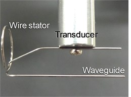
How to switch the traveling wave and the standing wave on the wire stator is explained. One wire stator has two waveguides, so vibration sources are connected to respective waveguide. The connection between the vibration source and the waveguide is shown in Fig. 13. The traveling wave is generated on the wire stator in forward rotation when the vibration source connected to the outside waveguide is operated. The traveling wave is generated on the wire stator in reverse rotation when the vibration source connected to the inside waveguide is operated. Traveling waves are synthesized on the wire stators to generate the standing wave when two vibration sources are operated simultaneously. Therefore, the traveling wave and the standing wave can be switched by the operation state of the vibration source.
The driving force is obtained by the duty ratio proportional to the time in which the traveling wave occurs in the period of generating the traveling wave and the standing wave when the input on state of PWM control is the traveling wave and the off state is the standing wave. One vibration source connected to the wire stator constantly generates traveling waves, while the other vibration source vibrates by the duty ratio. In addition, the standing wave dose not generate a friction force against the spherical rotor, so the driving of the spherical rotor is not prevented by the increase of the friction force.
Fig. 13Connection between transducer and waveguide
5.2. Experimental method of rotational direction using PWM control
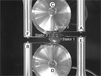
An experimental equipment shown in Fig. 14 is used to control the rotational direction of spherical ultrasonic motor using wire stators in order to investigate the effectiveness of PWM control. The spherical ultrasonic motor using wire stators is composed of one spherical rotor, four wire stators, and ultrasonic vibration sources. The Langevin transducer with resonant frequency of 24.6 kHz is used as an ultrasonic vibration source. Here, in order to control the rotational direction from No. 1 (Right) to No. 2 (Upper right) in Table 1, the vertical wire stators are connected with vibration sources, and the horizontal wire stators are connected with two vibration sources. In addition, the vibration sources are allocated by the alphabet from A to F. The vibration sources from A to D are connected to the outside waveguide of the wire stator, and the vibration sources of E and F are connected to the inside waveguide of the wire stator.
The output in forward rotation is synthesized so that the spherical rotor rotates upwards when the vibration sources from A to D are running. The standing wave is generated in the horizontal wire stators and the vertical output is affected and the spherical rotor rotates in the right direction when all the vibration sources are running from A to F. The horizontal output is regulated by the PWM control by the running time of the vibration sources of E and F, and the spherical rotor rotates by changing the rotational direction between the upper right and the right. The vibration sources of E and F output respectively from the same waveform generator to synchronize the output timing.
The amplitude and frequency of the AC voltage applied to the vibration source are 20 Vp-p and 24.6 kHz from A to F. The waveform generator used in the spherical ultrasonic motor using wire stators can adjust the generation time of AC voltage at a minimum of 0.001 s. In this study, an interval of 0.01 s is defined as a cycle. The duty ratio increases from 0 % to 90 % by 10 % and the rotational angle is respectively measured. The spherical rotor with the reference point is used and the angle between the trajectory of the reference point and the horizontal direction is defined as the rotational angle.
Fig. 14Experimental equipment of PWM control experiment
5.3. Experimental result of rotational direction using PWM control
Experimental results are shown in Fig. 15. The rotational angle becomes smaller and smaller with the increase of the duty ratio. The influence of the horizontal wire stator output is reduced when the rotational angle is small.
Fig. 15Relationship between duty ratio and angle of rotational direction
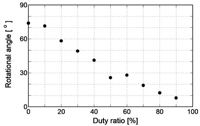
This result agrees with the initial idea that the horizontal wire stator output decreases with increasing the standing wave ratio. Therefore, the control method of the rotational direction using PWM control is effective.
The generation method of the standing wave is considered as the cause of a sudden decrease in the rotational angle when the duty ratio is 50 %. A waveform generator with 2 channel output is used. The output timing of the PWM control needs synchronization so that the same waveform generator is connected to E and F. Therefore, two traveling waves synthesized in the horizontal wire stators can be output from different waveform generators, and as a result the amplitude and frequency are considered to be slightly different.
6. Conclusions
In this study, the development of miniature spherical ultrasonic motor for directional adjustment of a vascular endoscopic camera is experimented. A miniature spherical ultrasonic motor using wire stators composed of spherical rotor, wire stator, waveguide, and vibration source is made. The wire stator is a single spiral stator and there are two waveguides on the outside and inside. The case where the vibration source is connected to the outside waveguide is defined as forward rotation, and the case where the vibration source is connected to the inside waveguide is defined as reverse rotation.
Firstly, the pressing force of ultrasonic motor is investigated. The relationship between the pressing force and rotational number is investigated, and it can be clarified that there is an optimum value for the pressing force and there is a difference between forward rotation and reverse rotation. Secondly, the starting torque which is one characteristic of the motor is investigated. The relationship between the frequency and amplitude of the AC voltage applied and the starting torque is investigated, and it can be clarified that there is a difference between forward rotation and reverse rotation. Finally, the rotational direction control of this motor is discussed. A PWM control method is proposed. The verification is carried out by the direction control experiment, and it can be shown that the proposed method is effective for the rotational direction control of miniature spherical ultrasonic motor using wire stators.
References
-
Mizuno K., Miyamoto A., Isojima K., Kurita A., Senoo A., Arai T., Kikuchi M., Nakamura H. A serial observation of coronary thrombi in vivo by a new percutaneous transluminal coronary angioscope. Angiology, Vol. 43, Issue 2, 1992, p. 91-99.
-
Thieme T., Wernecke K. D., Meyer R., Brandenstein E., Habedank D., Hinz A., Felix S. B., Baumann G., Kleber F. X. Angioscopic evaluation of atherosclerotic plaques: validation by histomorphologic analysis and association with stable and unstable coronary syndromes. Journal of the American College of Cardiology, Vol. 28, Issue 1, 1996, p. 1-6.
-
Uchida Y., Tomaru T., Nakamura F., Furuse A., Fujimori Y., Hasegawa K. Percutaneous coronary angioscopy in patients with ischemic heart disease. American Heart Journal, Vol. 114, Issue 5, 1987, p. 1216-1222.
-
Uchida Y., Hasegawa K., Kawamura K., Shibuya I. Angioscopic observation of the coronary luminal changes induced by percutaneous transluminal coronary angioplasty. American Heart Journal, Vol. 117, Issue 4, 1989, p. 769-776.
-
Cribier A., Jolly N., Eltchaninoff H., Koning R., Baala B., Kothari M., Chan C., Letac B. Angioscopic evaluation of prolonged vs standard balloon inflations during coronary angioplasty: A randomized study. European Heart Journal, Vol. 16, Issue 7, 1995, p. 930-935.
-
Siegel R. J., Ariani M., Fishbein M. C., Chae J. S., Park J. C., Maurer G., Forrester J. S. Histopathologic validation of angioscopy and intravascular ultrasound. Circulation, Vol. 84, Issue 1, 1991, p. 109-117.
-
Mizuno K., Arai T., Satomura K., Shibuya T., Arakawa K., Okamoto Y., Miyamoto A., Kurita A., Kikuchi M., Nakamura H., Utsumi A., Takeuchi K. New percutaneous transluminal coronary angioscopy. Journal of the American College of Cardiology, Vol. 13, Issue 2, 1989, p. 363-368.
-
Sashida T., Kenjo T. An Introduction to Ultrasonic Motors. Oxford University Press, Oxford, 1993.
-
Toyama S., Sugitani S., Zhang G., Miyatani Y., Nakamura K. Multi degree of freedom spherical ultrasonic motor. Proceedings of IEEE International Conference on Robotics and Automation, 1995, p. 2935-2940.
-
Takesue N., Ohara T., Ishibashi R., Toyama S., Hoshina M., Hirai Y., Fukaya N., Arata J., Fujimoto H. Position control methods of spherical ultrasonic motor. Proceedings of IEEE/RSJ International Conference on Intelligent Robots and Systems, 2010, p. 3061-3066.
-
Tanabe M., Xie S., Tagawa N., Moriya T., Furukawa Y. Development of a mechanical scanning-type intravascular ultrasound system using a miniature ultrasound motor. Japanese Journal of Applied Physics, Vol. 46, Issue 7B, 2007, p. 4805-4808.
-
Wang F., Nishizawa U., Toyama S. Multi degree-of-freedom micro spherical ultrasonic motor using wire stators. Vibroengineering Procedia, Vol. 10, 2016, p. 272-276.
Cited by
About this article

