Abstract
Ultrasonic Metal Welding is a green manufacturing technique and one of the most advanced solid state welding processes in which similar or dissimilar metallic components are joined by the application of high frequency vibrations (> 20 kHz) and pressure. Ultrasonic metal welding is accompanied by slip and plastic deformation so that the base metals being welded will not melt and in turn forms a homogenous coalescence of two metals at the joining area so that the joint retains the parent metal properties. The major problem faced by the industries using ultrasonic metal welding process is the poor weld quality and weld strength. The design of acoustic horn or sonotrode plays a dominant role in producing quality welds. The primary function of sonotrode is to vibrate at a level required for welding and also to transmit the vibration energy to the point where welding of metals takes place. For producing quality welds, the vibration energy is to be transmitted to the weld interface without much loss. Therefore, there is a need for accurate design of sonotrodes in ultrasonic metal welding process. This work focuses on designing a stepped sonotrode used for joining metallic wire with metallic sheet based on significant design parameters such as amplitude gain and von Mises stress factor using modal and harmonic analysis. Experimental trials are conducted using the stepped sonotrodes and the effectiveness of the designed sonotrodes is evaluated based on improvement of strength of the joint in tension.
1. Introduction
Ultrasonic Metal Welding (USMW) is a joining process in which two metallic specimens are joined by the application of ultrasonic vibrations under moderate pressure where the vibrations are applied at the interface between the weld specimens. USMW is the one of the most widely used advanced methods for welding non-ferrous metals such as aluminium (Al), copper (Cu), nickel (Ni), gold (Au) and silver (Ag). It eliminates most of the problems existing in traditional welding techniques, such as the fusion of metal through the application of heat by flame or electric arc in combination with cleaning and fluxing agents and sometimes filler metals. Ultrasonic welding of a metallic wire to a flat metallic sheet such as terminal plate or lead tab is a good example that needs in depth study.
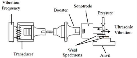
This type of joints is encountered in numerous industrial applications such as the consumer durable products, automotive components, switch gears, bus bars, fuses, circuit breakers, ignition modules, contacts, starter motors, microelectronic wires and battery connectors. The schematic representation of ultrasonic metal welding is shown in Fig. 1.
The main components of the USMW machine are the converter, transducer, booster, sonotrode, anvil and pneumatic system. The converter raises the standard electrical supply to the required operating frequency. The piezo-electric transducer converts high frequency electric supply into ultrasonic vibrations. The booster modifies the amplitude of the vibrations as applied to the sonotrode. The sonotrode transmits the vibrations to the work material which are held on an anvil in lap joint configuration. The pneumatic system moves the ultrasonic stack up and down to apply the required clamping pressure on the specimens to be welded. The quality of joints is influenced by predominant factors such as the composition and geometry of the weldment, hardness of the work piece, cleanliness of the surfaces to be joined, selection of welding conditions – power, clamping pressure, amplitude of vibration, weld time and tooling. During ultrasonic welding, the acoustic horn or sonotrode is in direct contact with the work material. The role of the sonotrode is to transmit and concentrate ultrasonic vibration at a spot where the materials are to be welded. The basic requirement of design of sonotrode is to obtain optimum amplitude of vibration at interface where weld is to be formed. The design of sonotrode is influenced by many factors such as the shape, size, profile and material. Due to the dynamic nature of sonotrode, significant research activities are carried out to study the dynamic characteristics of sonotrode configurations, fundamental modal properties such as the natural frequencies and mode shapes of the sonotrode using analytical and finite element analysis methods.
Fig. 1Ultrasonic metal welding system components
Kim et al. [1] discussed a method for designing the ultrasonic metal welding sonotrode based on modal and harmonic analyses. It was found that the largest amplitude change occurred at the tip of the sonotrode when the length of sonotrode is kept equal to half of the wave length of the sound wave passing through the sonotrode. The frequency characteristics of the sonotrode were analysed using ANSYS software. Ziad Al Sarraf [2] presented an approach for design and simulation of the ultrasonic sonotrode for spot welding that resulted in improved welding performance. Constantin et al. [3] performed finite element analysis on various sonotrodes profiles such as conical, exponential and parabolic cubical sonotrodes. The variation of the oscillation amplitude for different sonotrode profiles was reported. Jeong Seok Seo et al. [4] developed a one-wave length sonotrode operating at a resonant frequency of 40 kHz. The performance of the sonotrode was effectively verified by conducting experiments. This study also showed that the tip of the sonotrode was made to vibrate at the resonant frequency close to the working frequency of the metal welder used in the experiments. Vinod et al. [5] employed finite element method for designing sonotrodes used for ultrasonic machining. A systematic procedure was developed for the design of sonotrode. The double conical shape sonotrode was considered and various stress components in the sonotrode for several frequencies were studied and concluded that the stress induced in the sonotrode was minimum at resonance condition. Nad [6] reported that the performance of an ultrasonic welding equipment depends on proper design of sonotrode. The dynamic characteristics of different geometrical shapes of sonotrodes were presented in this work. Modal analysis was carried out by numerical simulation using finite element method. Amin et.al [7] established a computer aided design procedure for selection of sonotrode profile and material based on finite element analysis. A new design profile was suggested using parts with different geometries. An optimization procedure was adopted to obtain maximum magnification and safe working stresses based on the material used for fabrication of the sonotrode. Shuyu [8] analysed the propagation characteristics of the longitudinal and torsional vibrations in sonotrodes with exponential profiles and obtained the conditions for resonance of the longitudinal and torsional vibrations. Jeongdong et al. [9] designed a sonotrode for high power ultrasonic transducers using classical mathematical methods and numerical method. Based on the analysis, it was determined that a sonotrode with catenoidal profile provide larger amplification compared to the sonotrode with exponential profile. It was also indicated that the sonotrode with least curvature could possibly achieve larger amplification. Kuo et al. [10] made an attempt to design a rotary ultrasonic milling tool using finite element method. The harmonic piezoelectric vibrations of the ultrasonic milling system were simulated by finite element method to study on frequency, amplitude of the vibration and stress distribution.
Based on literature survey, it was found that only a few research works were reported by the researchers pertaining to the design issues of the stepped sonotrode. Evaluation of design of stepped sonotrode particularly used in lateral drive ultrasonic metal welding systems for joining metallic wire and sheet using design of experiments approach involving significant process parameters seems to be not reported. This work was carried out to fill this gap. The research work as reported in this paper, comprising of finite element analysis combined with experimental validation of performance of the sontrode will contribute an effective design approach to academic and industry practitioners.
Two different types of stepped sonotrode are considered in this work as shown in Fig. 2. The types of sonotrode are: Type I- the existing traditional sonotrode with dissimilar cross section and abrupt change in cross section commonly used for joining metallic wire with metallic sheet specimens in lateral drive ultrasonic metal welding systems, Type II- a sonotrode with similar circular cross section and gradual change in cross section using a tapered profile at the middle of the sonotrode.
Fig. 2Types of stepped sonotrode: a) type I, b) type II
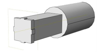
a)
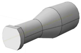
b)
A systematic study based on the methodology as shown in Fig. 3 is carried out for designing a stepped sonotrode using finite element analysis employing ABAQUS software followed by experimental investigation with the following objectives:
1) To extract the mode shapes and the corresponding natural frequencies of the stepped sonotrodes. CAD software is used to model the profile based on theoretical calculations.
2) To determine the dynamic characteristic design parameters such as amplitude gain and von Mises stresses developed in the stepped sonotrodes from finite element analysis.
3) To study the performance of the sonotrodes by conducting experiments and compare them for optimum performance. Joint strength in tension is measured for this purpose.
2. Design of sonotrode
Stepped sonotrode profile is used in variety of ultrasonic metal welding applications. The stepped sonotrode offer many advantages such as higher amplitude gain, ease of manufacture and extended service life [11]. Therefore, it is essential to design a sonotrode with higher amplitude gain while keeping the stress levels in the sonotrode as minimum as possible. The critical aspect of design of sonotrode for ultrasonic metal welding is that resonance frequency of the sonotrode must match the working frequency of the ultrasonic transducer. It is important to consider various aspects such as the selection of the working frequency, selection of the sonotrode material, establishment of the velocity of sound propagation in the selected sonotrode material and the calculation of the dimensions of the sonotrode. The governing equation for sonotrode is derived by considering an elastic medium subjected to longitudinal vibration. When a long slender bar as shown in Fig. 4 is excited along the axis, longitudinal vibration occurs, and it undergoes axial deformation. Therefore, a straight bar with length and cross section area is subjected to a longitudinal displacement given by . The basic assumptions are that the medium is homogeneous, isotropic and has free-free boundary condition.
Fig. 3Methodology for design of ultrasonic horn
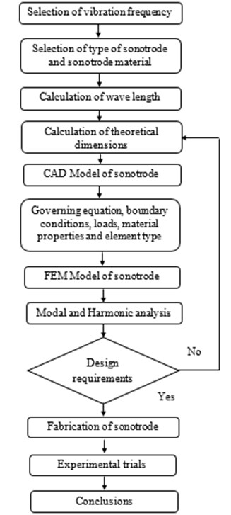
Fig. 4Long slender bar
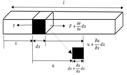
The governing equation of the bar is derived by considering that refers to a point location along the section of the bar and the bar has a small element . When this element is subjected to an applied force , the element moves from its initial position with a displacement and the change in displacement is. The length of the element is increased to | as shown in Fig. 4. The stepped sonotrode is designed on the basis of axial vibration of an elastic member with varying cross section. The plane wave propagation in the bar is assumed to be only in axial direction and propagation along lateral directions is neglected. The generalized wave equation, which governs the acoustic behaviour of the sonotrode with change in cross section is shown in Eq. (1):
where is velocity of propagation of sound through sonotrode and is given by Eq. (2):
Here, is the frequency at which sonotrode vibrates (20,000 Hz), is the wave length of ultrasonic waves in m, is the Modulus of Elasticity in N/m2 and is the density of the material in kg/m3.
The selection of material is the fundamental step in the design of sonotrode. The materials such as tool steel, die steel, maraging steel and titanium are commonly used for making sonotrode used for welding soft metals. The sonotrode material considered in this work is AISI D2 steel and the material properties of the AISI D2 steel is shown in Table 1.
Table 1Material properties of AISI (American iron and steel institute) D2 steel
Parameter | Value |
Density | 7850 Kg/m3 |
Modulus of elasticity | 210 GPa |
Poisson’s ratio | 0.30 |
Sonotrodes may be of full wavelength or half wave length. The half wave length sonotrode is generally used for ultrasonic metal welding applications so as to save the material and reduce manufacturing cost. The half wave length sonotrode is considered in this work. The geometrical dimensions and the material of the sonotrode play a significant role in enhancing the performance of the sonotrode. The geometry and governing dimensions of the standard stepped sonotrode is shown in Fig. 5.
The total length of the sonotrode () considered in this work is half of the wave length(/2) of waves passing through it and is divided into two equal parts L1 and L2. The total length of the sonotrode is calculated using Eq. (2):
Normally, the area of cross sections at the larger end and the smaller end are in the ratio 2:1 ratio for steel and in the ratio 3:1 for titanium. This is for improved acoustical performance [9]. The specifications of the designed sonotrode are shown in Table 2. The commercially available software Pro/Engineer Wildfire 4.0 is used to develop CAD models of the sonotrode. The sonotrodes are modeled based on the calculated theoretical dimensions.
Fig. 5Geometry and governing dimensions of standard stepped sonotrode [4]
![Geometry and governing dimensions of standard stepped sonotrode [4]](https://static-01.extrica.com/articles/19648/19648-img6.jpg)
Table 2Specifications of sonotrode
Parameter | Value |
Total Length of the sonotrode | 129 mm |
Half-length | 64.5mm |
Large diameter | 38 mm |
Small diameter | 22 mm |
Displacement load | 30 to 60 μm |
Working frequency | 20 KHz |
3. Finite element analysis of sonotrode
The commercially available ABAQUS/CAE 6.12 “Standard / Explicit Model” software is used in this work to analyse the design of the ultrasonic metal welding sonotrode. The modal analysis is performed on the sonotrodes to obtain possible mode shapes and the harmonic analysis is performed to obtain amplitude gain and von Mises stress developed in the sonotrodes. Since sound wave propagates through the sonotrode, the generalized wave Eq. (3) is applicable in this analysis. The meshing of the CAD model requires care as the accuracy of the results depends on the type of element, number of elements and variation in size of the elements. The element used in meshing the sonotrode models is standard C3D10. This element is a general purpose tetrahedral element with a very attractive capability for automatic meshing and provides better results in vibration analysis. Table 3 shows the FEM models of sonotrode. During analysis, the material of the sonotrode is assumed to be homogenous, isotropic and there is no change in material properties along the length of the sonotrode. The fixed boundary condition as shown in Eq. (4) is applied at the transducer end of the sonotrode by constraining all degrees of motion. The range of frequency is set between 0-25 kHz. Lanczos method is used to determine the natural frequency of the sonotrode:
Various mode shapes of the sonotrodes such as bending, extension and twisting and the corresponding natural frequencies are obtained using finite element analysis and are shown in Table 4. From the mode shapes identified, the extension mode shape is selected according to the application and then harmonic analysis is carried out for the extension mode shape of each of the types of sonotrode. The pre-processing of Type II sonotrode for harmonic analysis is shown in Fig. 6 and the analysis was carried for both the types of sonotrodes. Generally, for many of the ultrasonic metal welding applications pertaining to joining of metallic wire and sheet, the input amplitude of vibration of the sonotrode used is in the range of 30 to 60 µm and the clamping pressure used is in the range of 2 to 5 bar. In this work, analysis is carried out by providing input amplitudes of 30 µm, 40 µm, 50 µm and 60 µm at the transducer end of the sonotrode and the maximum clamping pressure of 5 bar applied on the tip of the sonotrode as shown in Fig. 6.
Fig. 6Pre-processor model of type II sonotrode
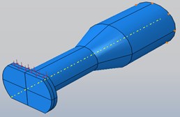
Table 3FEM models of various types of stepped sonotrode
Sonotrode type | Meshed sonotrode |
Type I | 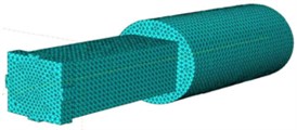 |
Type II | 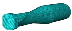 |
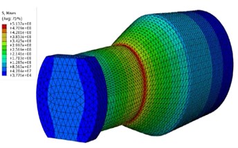
Since the sound wave propagates through the sonotrode, the length of the sonotrode is made equal to half the wave length [1] to obtain maximum amplitude of the vibration at the tip of the sonotrode. It is essential to have a gain for the amplification of the vibration amplitude from the transducer end to the required level at the tip. The amplitude gain is computed theoretically as 2.98 using Eq. (5) [3]. From the results obtained from harmonic analysis as shown in Fig. 7 and Fig. 8 the amplitude gain is found to be 2.35 for Type I sonotrode and 2.85 for Type II sonotrode for an input amplitude of 30 µm. The results of analysis are compared with the amplitude gain value obtained theoretically. It is clear that for Type II sonotrode the amplitude gain is in close agreement with amplitude gain value obtained theoretically than that for Type I sonotrode:
where, – diameter at the larger end in mm, – diameter at the smaller end in mm.
In practice, the duration of safe working of sonotrode for producing defect free joints is of significant requirement. The service life of the sonotrode is a vital parameter which ultimately depends on both design of sonotrode and the operational parameters. The stresses developed at the time of operation must be at safe levels for a sonotrode to have effective useful life. On account of this, an analysis is performed to determine the von Mises stress in both the types of sonotrodes. The von Mises stress obtained using the input parameters of 30 µm amplitude and 5 bar pressure for the two types of sonotrodes are shown in Fig. 9. Similarly, analysis is carried out to determine von Mises stress at other input amplitudes of 40 µm, 50 µm and 60 µm. Since it is not possible to put all the analysis results pictorially the analysis results are shown in Table 5 and the values are plotted in Fig. 10. From the harmonic analysis it is evident that Type II sonotrode has a significant amplitude gain of 2.85 and minimum von Mises stress of 1027 N/mm2 at maximum input amplitude of 60 µm which is significantly low compared with Type I sonotrode. On an average, there is 57 % of reduction in stress levels at different input amplitudes in Type II sonotrode. The experiments are conducted to study the performance of the sonotrode.
Table 4Mode shapes of the sonotrodes
Type | Mode shape-bending | Mode shape-extension | Mode shape-twisting |
I | 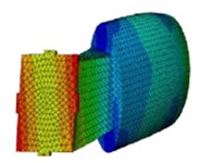 | 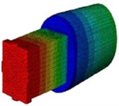 | 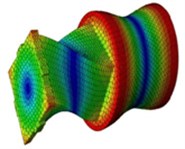 |
17562 Hz | 19522 Hz | 23014 Hz | |
II | 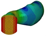 | 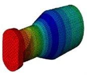 | 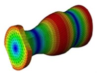 |
16839 Hz | 19814 Hz | 24703 Hz |
Fig. 7Amplitude gain for Type I Sonotrode = 2.35
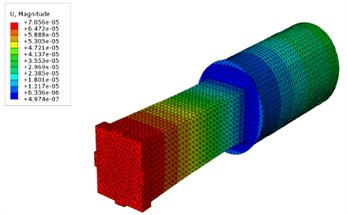
Fig. 8Amplitude gain for Type II Sonotrode = 2.85
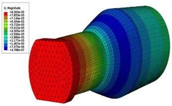
Fig. 9Von Mises stress (at 30 µm input amplitude, 5 bar pressure) in: a) Type I sonotrode, b) Type II sonotrode
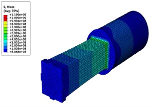
a)
b)
Fig. 10Von Mises stresses at various input amplitudes for Type I and II sonotrode
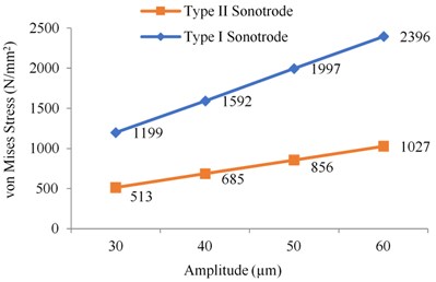
Table 5Simulation results of von Mises stresses at 5 bar pressure
Sonotrode Type | Von Mises stress (N/mm2) at input amplitude | |||
30 μm | 40 μm | 50 μm | 60 μm | |
Type–I sonotrode | 1199 | 1592 | 1997 | 2396 |
Type–II sonotrode | 513 | 685 | 856 | 1027 |
4. Details of experiments
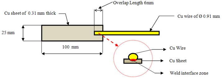
The purpose of conducting experiments is to evaluate the performance of the customized Type II sonotrode over the standard Type I sonotrode. The performance of sonotrodes can be evaluated by comparing the strength of the joint in tension obtained by both the sonotrodes. The Type II sonotrode is fabricated using MAKINO CNC machining center. The experimental trials are conducted based on Taguchi’s method. Taguchi’s method of experimental design provides a simple, efficient and systematic approach for conducting experimental trials. Based on considering three factors at three levels, L9 orthogonal array is employed[13]for conducting experimental trials. Ultrasonic welding trials are conducted using a conventional lateral drive ultrasonic metal welding machine (2500 W, 20 kHz) for different ranges of weld parameters. The specimens used in this work are the copper sheet (as received) of 100 mm length, 25 mm width, 0.31 mm thickness and the copper wire (as received) of 0.91mm diameter and 100 mm length with an overlap length of 6 mm in lap joint configuration [14]. The schematic representation of the joint is shown in Fig. 11. The experimental setup and the fabricated Type II sonotrode are shown in Fig. 12.
Fig. 11Schematic representation of weld specimen
The quality of the joint depends on many parameters. In this work, the parameters such as weld time, clamping pressure and amplitude of vibration of the sonotrode [15-17] are identified as control factors and varied at three levels as shown in Table 6.
Fig. 12a) Experimental setup, b) type II sonotrode
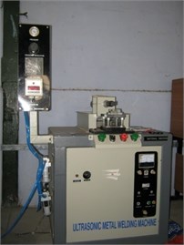
a)
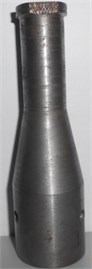
b)
The strength of the joint in tension is considered as the response variable. Two replicates of each experimental trial are conducted and the average of two results is considered as the strength of the joint in tension. The weld specimens are prepared according to ASTM international codes [12] for testing the strength of the joint by tensile loading. A 10 kN tensile testing machine is used to determine the joint strength of the specimens. The specimens (as received) are cleaned with acetone to remove the surface impurities. The experimental trials conducted using Type I sonotrode is shown in Table 7 and the experimental trials conducted using Type II sonotrode is shown in Table 8. Based on the experimental results, it is found that the strength of joints obtained using the Type II sonotrode is more than the strength of specimens obtained using Type I sonotrode. The welded specimens and the tensile testing loading conditions of the welded specimens are shown in Fig. 13.
Table 6Process parameters and the levels
Parameters | Designation | Level 1 | Level 2 | Level 3 |
Amplitude of vibration of the sonotrode (µm) | A | 30 | 42.5 | 57 |
Clamping pressure (bar) | B | 2 | 3 | 4 |
Weld time (sec) | C | 3 | 4 | 5 |
Table 7Experimental results using type I sonotrode
Trial No. | Clamping pressure (bar) | Amplitude of vibration of the sonotrode (μm) | Weld time (sec) | Experimental values | ||
Trial I tensile load (N) | Trial II tensile load (N) | Average tensile load (N) | ||||
1 | 2 | 30 | 2 | 162.59 | 161. 09 | 161.84 |
2 | 3 | 30 | 2.5 | 164.574 | 168.13 | 166.352 |
3 | 4 | 30 | 3 | 155.743 | 157.395 | 156.569 |
4 | 2 | 42.5 | 2 | 169.582 | 163.764 | 166.673 |
5 | 3 | 42.5 | 2.5 | 166.563 | 162.861 | 164.712 |
6 | 4 | 42.5 | 3 | 159.235 | 160.143 | 159.689 |
7 | 2 | 57 | 2 | 173.478 | 171.894 | 172.725 |
8 | 3 | 57 | 2.5 | 174.585 | 170.865 | 172.686 |
9 | 4 | 57 | 3 | 165.916 | 165.685 | 165.80 |
Table 8Experimental results using type II sonotrode
Trial No. | Clamping pressure (bar) | Amplitude of vibration of the sonotrode (μm) | Weld time (sec) | Experimental values | ||
Trial I tensile load (N) | Trial II tensile load (N) | Average tensile load (N) | ||||
1 | 2 | 30 | 2 | 222.674 | 224.348 | 223.511 |
2 | 3 | 30 | 2.5 | 225.892 | 223.385 | 224.638 |
3 | 4 | 30 | 3 | 216.235 | 219.547 | 217.891 |
4 | 2 | 42.5 | 2 | 229.415 | 223.859 | 226.637 |
5 | 3 | 42.5 | 2.5 | 229.808 | 227.670 | 228.739 |
6 | 4 | 42.5 | 3 | 221.745 | 224.632 | 223.188 |
7 | 2 | 57 | 2 | 229.896 | 233.325 | 231.610 |
8 | 3 | 57 | 2.5 | 230.105 | 231.874 | 230.989 |
9 | 4 | 57 | 3 | 224.872 | 228.543 | 226.707 |
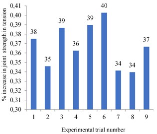
The increase in tensile strength of the welded joints for each experimental trial using Type II sonotrode is compared with strength of the joint values obtained using Type I sonotrode. The percentage increase in strength of the joint for each experimental trial is shown in Fig. 14. This increase in strength of the joint thus obtained using Type II sonotrode is due to higher amplitude gain and of the changes in the tip of the sonotrode. For the weld joint to have adequate strength, the specimens are to be pressed and rubbed against each other by the sonotrode tip.
The Type I sonotrode tip has a square tip of side 5 mm for pressing the metallic wire on the flat surface wherein the metallic wire tends to slip when both clamping pressure and ultrasonic vibrations are applied through the sonotrode on the weld specimens. In Type II sonotrode, the sonotrode tip is made uniform and has a rectangular tip of length of 20 mm and width of 5 mm wherein the ultrasonic vibrations and clamping pressure are transmitted efficiently to the weld specimens thereby improving the strength of the joint. Hence, the performance of customized Type II sonotrode is effective than Type I sonotrode.
Fig. 13a) Welded specimens, b) tensile testing of the weld specimen
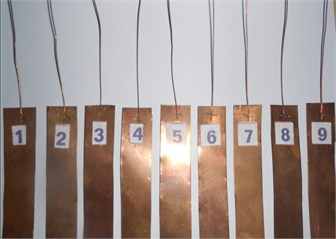
a)
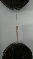
b)
Fig. 14Percentage increase in strength of the joint using Type II sonotrode
5. Conclusions
In this work, an investigation was carried out for designing sonotrodes used for joining metallic wire with a flat metallic surface. The dynamic characteristics of the two different types of stepped sonotrodes were studied and reported. The finite element analysis results and experimental results revealed the following with regard to design, analysis and performance of the sonotrode.
The modal analysis demonstrated various mode shapes in bending, extension and twisting modes of sonotrodes. The sonotrodes were designed to operate at longitudinal extension mode shape. These mode shapes for Type I and Type II sonotrode were obtained at 19552 Hz and 19814 Hz respectively using finite element analysis.
Harmonic analysis was performed to determine the amplitude gain and the stresses induced in the sonotrodes. The amplitude gain of the stepped sonotrode was analytically computed as 2.98 and the amplitude gain results obtained using ABAQUS software were 2.35 and 2.85 for Type I and Type II sonotrodes respectively.
The von Mises stress developed in both the types of sonotrode was analyzed and it was found that the Type II sonotrode was subjected to minimum stress level compared to Type I sonotrode. The stress levels were reduced by 57 %. This reduction in stress was due to the provision of gradual change in cross section at the middle of the sonotrode and could result in enhancement of useful life of the sonotrode.
The performance of the sonotrodes was evaluated by conducting experimental trials. The tensile strength of the weld specimens obtained using Type I sonotrode was compared with tensile strength of the weld specimens obtained using Type II sonotrode. The joint strength in tensile loading conditions was increased by 37 % using Type II sonotrode.
The scope of this work can be further extended with a study on service life of sonotrode based on wear at the tip of the sonotrode, change in geometric shape, geometric dimensions and material of the sonotrode based on shape optimization. based on shape optimization. The T-Peel strength of the joint can also be considered for comparison of strength of the joints.
References
-
Seon Ah Kim, Ho Su Jang, Eum Mi Kim, Dong Sam Park Vibration analysis of ultrasonic metal welding horn for optimal design. International Conference on Mechanical, Industrial, and Manufacturing Technologies, 2010.
-
Ziad Al Sarraf Design and simulation of the ultrasonic spot welding horn used to improve weld performance. World Journal of Engineering, 2010, p. 53-54.
-
Radu Constantin, Amza Gheorghe, Apostolescu Zoie Finite element modeling and analysis of simple ultrasonic horns. Proceedings of 1st International Conference on Visualization, Imaging and Simulation, 2008, p. 173-178.
-
Jeong Seok Seo, Ho Su Jang, Dong Sam Park Ultrasonic welding of Ni and Cu sheets. Materials and Manufacturing Processes, Vol. 30, Issue 9, 2014, p. 1069-1073.
-
Vinod Yadava, Aniruddha Deoghare Design of horn for rotary ultrasonic machining using the finite element method. International Journal of Advanced Manufacturing Technology, Vol. 39, 2008, p. 9-20.
-
Nad M. Ultrasonic horn design for ultrasonic machining technologies. Applied and Computational Mechanics, Vol. 4, 2010, p. 79-88.
-
Aminsg, Ahmedmhm, Youssefha Computer aided design of acoustic horns for ultrasonic machining using finite element analysis. Journal of Materials Processing Technology, Vol. 55, 1995, p. 254-260.
-
Lin Shuyu Study on the longitudinal – torsional composite mode exponential ultrasonic horns. Ultrasonics, Vol. 34, 1996, p. 757-762.
-
Jeong Woo, Yong Rae Roh P20-7 Design and construction of acoustic horn for high power ultrasonic transducers. Proceedings of IEEE, Ultrasonics Symposium, Vancouver, Canada, 2006, p. 1922-1925.
-
Kuo Kei Lin Design of rotary ultrasonic milling tool using FEM simulation. Journal of Materials Processing Technology, Vol. 201, 2008, p. 48-52.
-
Dale Ensminger Ultrasonics – Fundamentals, Technology, Applications. Marcel Dekker, New York, 1988.
-
Standard Test Method for Apparent Shear Strength of Single – Lap- Joint Adhesively Bonded Metal Specimens by Tension Loading (Metal-to-Metal). ASTM International, Vol. 1, 2005, p. 52-55.
-
Ranjit Roy K. Design of Experiments Using the Taguchi Approach. John Wiley and Sons, Canada, 2001.
-
Heinz Stefan, Wagner Guntram, Eifler Dietmar Ultrasonic welding of wires and cables. Journal of the Minerals, Metals and Materials Society, Vol. 64, Issue 3, 2012, p. 421-426.
-
Roopa Rani M., Rudramoorthy R. Computational modeling and experimental studies of the dynamic performance of ultrasonic horn profiles used in plastic welding. Ultrasonics, Vol. 53, Issue 3, 2013, p. 763-772.
-
Elangovans, Prakasan K, Jaiganesh V. Optimization of ultrasonic welding parameters for copper to copper joints using design of experiments. International Journal of Advanced Manufacturing Technology, Vol. 51, Issue 1, 2010, p. 163-171.
-
Mantra Prasad Satpathy, Bikash Ranjan Moharana, Shailesh Dewangan, Susanta Kumar Sahoo Modeling and optimization of ultrasonic metal welding on dissimilar sheets using fuzzy based genetic algorithm approach. Engineering Science and Technology, an International Journal, Vol. 18, Issue 4, 2015, p. 634-647.
Cited by
About this article

The authors are thankful to University Grants Commission, New Delhi for funding this research work, under Major Research Project Scheme (F. No. 42-876/2013 (SR)). The authors express their sincere and heartfelt thanks to the management and to the principal of PSG College of Technology, Coimbatore for extending the essential support and infrastructure to carry out this work.
