Abstract
Cardiovascular diseases are the leading cause of death among people up to 65 years old. One of the most common cardiovascular disease is thrombosis. To remove the blood clot inside the artery, usage of advanced invasive mechanical devices is needed. There is a need for the new alternative less risky and hazardous way of arterial thrombosis treatment. This paper presents a new design of a less risky ultrasonic blood vessels cleaning system.
1. Introduction
Some of cardiovascular diseases appear because of the thrombus [1, 2]. Incensement of more and more cases of diseases such as obliterative atherosclerosis [3], obliterative thromboangiitis, venous thrombosis, deep vein thrombosis [4], etc. is noticed. Nowadays these pathologies are being cured by huge spectra of various ways of treatment, developed to restore the blood flow inside the artery, using invasive fermentative and mechanical thrombus removal tools.
Nevertheless, application of current treatment methods is limited due to common surgery complications. There is a need for the new alternative less risky and hazardous way of arterial thrombosis treatment.
During the last few years, ultrasonic methods, which are the most perspective among restoring blood flow in the artery, affected by arterial thrombosis, attracts more and more attention. It is related to the increasing number of researches in the field of ultrasound impact human body tissues. Recent researches [5] showed that low frequency and intensity ultrasound increases elasticity of the damaged artery walls.
2. Mathematical model
The tube-shaped ultrasound waveguide wire with orifices at its operational end was offered as the alternative to some currently patented interventional thrombosis treatment solutions. The principal scheme of the tip of the waveguide is presented below in Fig. 1.
The waveguide wire of 260 mm in length and 1.5 mm in diameter is considered to be an interventional medical device. It can be used for cleaning the inner walls of arteries. It can also be used as a tool to break down and destroy the thrombus and simultaneously suck out the scurf of the blood clot being dissipated.
Adequate feed of the drugs to the damaged site of the blood vessel is secured by the unique design of the wire. The lug that enables the device to get attached to the concentrator is separated from the tube intended for drug infusion. Fig. 1 shows its construction in detail. The diameter of the intake is 1.1 mm.
The waveguide wire of such a structure allows impacting the occlusion not only mechanically but also by the flow of physiological fluid infused through the intake.
Fig. 1Tip of the waveguide: 1) blood vessel wall, 2) occlusive derivative, 3) waveguide, 4) wall of the waveguide
To ensure efficient delivery of a sufficient quantity of drugs to the required site of the artery to be treated, a tube-shaped waveguide wire was selected. The orifices drilled at the end of it act both as intake and suction holes, if necessary.
Mathematical modelling of the waveguide and its interaction with the operational environment involved the device detailed in Figs. 1 and 2. With the aim to gain better understanding of hydrodynamic processes, modelling did not take into consideration the fact that the waveguide is normally operating in the second tube-catheter which serves to protect the blood vessel against negative notes distributed over entire waveguide at particular steps of its length (experimentally determined notes and antinodes will be covered in Chapter 4 that follows below). For the sake of simplicity of the mathematical model it was also assumed that when operated the tip of the waveguide moves in circles instead of ellipses. Working regime of the waveguide tip were selected based on the results obtained from the mathematical model.
Fig. 2Input data for the task being solved through modelling: 1) wall of the blood vessel, 2) liquid medium (blood), 3) tip of the waveguide moving in circles
2.1. Description of caverns
Mathematical calculations were performed based on references [5-9] The cavern beside the tube is defined as the difference of velocities as follows:
when and 0 for every other Let’s denote the reduced velocity as follows:
then:
where – the angle to the centre of the tube cavern, – angular width of the tube cavern.
The reduced velocity of the tissue is similarly defined:
and tissue cavern:
Eq. (3) and (5) show that functions of caverns and are defined in analogous manner, thus further calculations involve description of the tissue cavern only, whereas tube cavern is offered too but only by writing up an asterisk.
If represents an integrated periodic function in range , , the following can be formulated:
where , represent the real numbers. In order to apply the outside conditions, the Eq. (6) must be regrouped into the periodic function over the entire range , as follows:
where coefficients of Fourier series are as follows:
Incorporation of Eq. (6) into Eq. (9) results in the following:
where:
The second equation in the Eq. (9) after the function is incorporated into it, allows other Fourier coefficients to be calculated as follows:
Here:
If position and length of the cavern, i.e. numbers and are the selected ones, then all the , , , are known values.
The following can be obtained from Eq. (12), when 0:
All the formulas proposed here can be also applied for the tube cavern by using and instead of and .
2.2. Displacements of the caverns
Velocities have been investigated as periodic functions of the argument . Such an argument shows that with the change in the angle by or change in time by , all the functions remain unchanged. Accordingly, it can be stated that steady-state solution somewhat turns around axis without experiencing any changes.
For the sake of simplicity, calculation of caverns involved 0 which in turn resulted in a somewhat instantaneous picture of the cavern Eq. (6) where 0. Since the cavern turns at the same angular velocity as the entire steady-state solution, the law of cavern motion Eq. (6) must be generalized in the following manner:
Here it is understood that 0 was incorporated. When , velocities are:
The integration of Eq. (12) and (13) by time results in the reduced displacements of the tissue and the fluid as follows:
Here represents the constant that generally can be a function of the angle . Actual displacements can be assumed to be as follows:
Here represents amplitude of the sliding displacement of the tube. Incorporating 0 allows obtaining the form of the cavern when :
The tube’s cavern is defined in absolutely the same manner:
Determination of the constants , requires for additional physical data that should be associated with pressure and gas flow within the caverns.
Since 0, as otherwise it would mean that the cavern simply does not exist, and , as in this case the cavern would be present around the entire perimeter of , then as it can be understood from Eq. (17), in order to have 0, it must be as follows:
If 0 and 0 at every 1, 2, 3,..., , then it can be derived from Eq. (18) that , . If 0 and 0, 1, 2, 3,..., , then it can be expressed as , , and result in equations with the unknown quantities , . However, there is always a good chance that any of the factors , (or ) can turn out to be infinitely huge and impede computation. The simplest option is apparently to write equations and then to supplement them with Eq. (18) and following equations:
This way, the system of linear equations is obtained with unknown quantities , , ,
Both caverns that of a tube and that of a tissue are described through a general system of equations. Both caverns are interdependent and cannot be investigated separately one by one.
Fig. 3Formation of caverns (that of the tube – solid line, that of the tissue – dotted line)
2.3. Calculation of the size of the cavern
Solving the task of modelling lead to the observation that during the operation of the ultrasonic system, a cavity containing tenuous gas, here referred to as the cavern, is formed at the wall of the blood vessel.
Fig. 4Formation of the cavern where: 1) wall of the blood vessel, 2) cavern, 3) liquid environment (blood), 4) tip of the waveguide
Thickness of the outside layer can be calculated when the surface is vibrating at 23.185 kHz frequency in its own plane as follows:
Here, viscosity of water is incorporated 0.73·10-2 cm2/s, at the temperature of 35 °C. Vibration frequency is 13.7·104 rad/s.
3. Experimental investigation of waveguide wire influence to surrounding fluids
During operation of the device under research, cavitation process and friction between the waveguide and surrounding fluids cause temperature to rise drastically. Human body temperature above 42°C is well known to cause fatality, as red blood cells undergo in vivo haemolysis [10]. Taking this into consideration, the next series of experiments on human blood were undertaken. For this purpose, thermovisor FLIR SC7000, generic generator, PC and the tube-shaped waveguide system was used. Fig. 5 shows the setup and schematic view of the experiment accomplished.
Fig. 5Experimental setup, where: 1) waveguide in a tube filled with water, 2) thermovisor FLIR SC7000, 3) generator; 4) PC
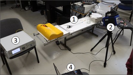
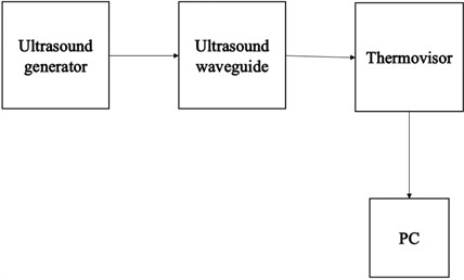
Fig. 6Schematic view of the experiment
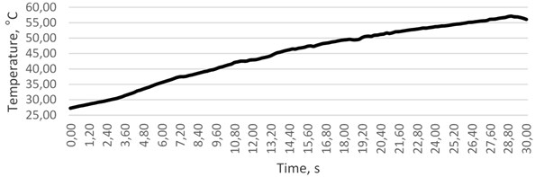
The first experiment was carried by using the operating system inside the tube with the diameter of 3 mm, which, in its structure, was very similar to a human artery. Data gathered in a course of the experiment revealed that it takes as little as 4 seconds to reach the lethal temperature of 42 °C (when the starting point was 36 °C).
Fig. 7The variation of temperature in time, °C
The measurement of intensity of cavitation during the experiment was conducted by using various fluids: water, blood replacement fluid and fluids with nanoparticles. As we have found, the highest level of cavitation acoustic emission is at blood replacement fluid and the same fluid with nanoparticles. This was caused by the higher fluid density.
Waveguide was placed into the vessel with a liquid (water). After actuating signal was generated, longitudinal vibrations of the hub end were turned into wire transverse vibrations and the standing wave was formed. Standing waves in the bubble zone were characterized by intense dissolution of dissolved gases (Figs. 8, 9). In this case, cavern is created by the vibrations, and this phenomenon causes cavitation process.
Fig. 8Resonance vibrations of the wire in the fluid
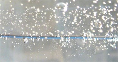
Fig. 9Experiment during time period of 0-0.4 s
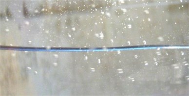
Fig. 8 shows the how gas is extracted from the water, while the small bubbles appear near the wire. The process becomes more intensive over the time, because the amplitude of the wire vibration increases. Also, we can see that the gas extraction process becomes continuous and accompanied by cavitation.
The results of experimental investigation have showed that vibrating waveguide creates cavitation (Fig. 8, 9), which is caused by mathematically proved cavern rotation about the end point of the waveguide and temperature changes (Fig. 7).
4. Conclusions
The mathematical model of the waveguide and its operational environment, in this particular case – human blood, confined by biological human tissues (wall of the blood vessel) has been developed. In the course of solution of the mathematical task a highly important phenomenon was revealed: with the waveguide operating under resonant regime, a pocket containing tenuous gas in size of up to 2.3 μm is formed at the wall of the blood cell that keeps sliding along the wall of the blood cell at the speed of the waveguide rotation. It can have a significant effect on the energy balance in medium in which the waveguide is operated and also may significantly affect an absorption of drugs through the wall of the blood vessel and may influence on a large scale the effect that ultrasonic system has on the occluding malformation of the vascular walls.
Theoretical calculations have showed that the 23.185 Hz frequency of the waveguide raises water temperature at 35 °C. Although, the experimental investigation revealed that temperature alteration depends on excitation time which is very important while operating with blood. This phenomenon has not yet been addressed and requires to be experimentally investigated in further research.
References
-
Li H., Horke S., Förstermann U. Vascular oxidative stress, nitric oxide and atherosclerosis. Atherosclerosis, Vol. 237, Issue 1, 2014, p. 208-219.
-
Alexopoulos N., Katritsis D., Raggi P. Visceral adipose tissue as a source of inflammation and promoter of atherosclerosis. Atherosclerosis, Vol. 233, Issue 1, 2014, p. 104-112.
-
Tzirtzilakis E. E. Biomagnetic fluid flow in an aneurysm using ferrohydrodynamics principles. Physics of Fluids, Vol. 27, Issue 6, 2015, p. 061902.
-
Abdullah B. J. J., Mohammad N., Sangkar J. V., Aziz Y. A., Gan G. G., Goh K. Y. Incidence of upper limb venous thrombosis associated with peripherally inserted central catheters (PICC). The British Journal of Radiology, Vol. 78, 2005, p. 596-600.
-
Bubulis A., Garalienė V., Jurėnas V., Navickas J., Giedraitis S. Effect of low-intensity cavitation on the isolated human thoracic artery in vitro. Ultrasound in Medicine and Biology, Vol. 45, 2017, p. 1040-1047.
-
Abamowitz Ed. M., Stengun I. A. Handbook of Mathematical Functions. New York, Dover, 1970.
-
Timoshenko S. P., Goodier J. N. Theory of Elasticity. McGraw-Hill, New York, 1970.
-
Chen E. J., Novakofski J. Young’s modulus measurements of soft tissues with application to elasticity imaging. IEEE Transactions on Ultrasonics, Ferroelectrics, and Frequency Control, Vol. 43, Issue 1, 1996, p. 191-194.
-
Rektorys K. Variational Methods in Mathematics, Science and Engineering. D. Reidel Publishing Company, London, 1980.
-
Choi J. W., Pai S. H. Changes in hematologic parameters induced by thermal treatment of human blood. Annals of Clinical and Laboratory Science, Vol. 32, Issue 4, 2002, p. 393-397.
About this article

This research is funded by Research Council of Lithuania, Project No. MIP-097/15.
