Abstract
Cardiovascular diseases are the leading cause of death among people up to 65 years old. One of the most common cardiovascular diseases is arterothrombosis. For recanalization of arteries usage of advanced invasive mechanical devices is required. The tube-shaped ultrasound waveguide wire was designed, investigated and validated by computational finite element method and experimental techniques.
1. Introduction
Heart and cardiovascular diseases related to iliac, femoral, and radial artery pathologies might appear because of the arterosclerotic plagues and thrombus [1, 2]. Incensement of more and more cases of diseases such as obliterative atherosclerosis [3], obliterative thromboangiitis, venous thrombosis [4], deep vein thrombosis [5], etc. is noticed. Nowadays these pathologies are being cured by huge spectra of various ways of treatment, developed to restore the blood flow through the artery, using invasive fermentative and mechanical thrombus removal tools.
Nevertheless, application of current treatment methods is limited due to common surgery complications. There is a need for the new alternative less risky and hazardous way of arterial thrombosis treatment.
During the last few years, ultrasonic methods, became the most perspective among restoring blood flow in the artery, affected by arterial thrombosis, attracts more and more attention. It is related to the increasing number of researches in the field of ultrasound impact on human body tissues. Recent researches [6-9] showed that low frequency and intensity ultrasound increases elasticity of the damaged artery walls.
In this article a computational model based on Finite element method (FEM) is used for the simulation to investigate behavior of the newly designed ultrasound system. The model of the waveguide wire, lug and a screw was implemented in COMSOL Multiphysics package. The mentioned system was also investigated experimentally.
This article is organized as follows. The review of current ultrasound systems for invasive blood vessel treatment is given in Section 2. The design of the tube-shaped ultrasound wave guide wire is given in Section 3. Computational simulation and its results of tube-shaped ultrasound wave guide wire are given in Section 4. Results of experimental research are given in Section 5. Conclusions are given in Section 6.
2. Current solutions
A review of currently available invasive arterial thrombosis treatment tools can be seen in Fig. 1. After the invention of ultrasonic resonator in 2003 [10], few other ultrasound systems were developed. The most noticeable one is marked in Fig. 1(c). The mentioned system provides the option to transfer the limited volume of drugs to the spot where arterial thrombosis caused clot appeared during the invasive surgery. Despite the novelty of the design, it is limited due to volumetric limitation and durability problems of the spring.
Fig. 1Current patented ultrasound wave guide wire construction, where: a) ultrasonic resonator [10], b) steerable ultrasound catheter [11], c) ultrasound wave guide wire for internal blood vessels cleaning [12]
![Current patented ultrasound wave guide wire construction, where: a) ultrasonic resonator [10], b) steerable ultrasound catheter [11], c) ultrasound wave guide wire for internal blood vessels cleaning [12]](https://static-01.extrica.com/articles/18359/18359-img1.jpg)
a)
![Current patented ultrasound wave guide wire construction, where: a) ultrasonic resonator [10], b) steerable ultrasound catheter [11], c) ultrasound wave guide wire for internal blood vessels cleaning [12]](https://static-01.extrica.com/articles/18359/18359-img2.jpg)
b)
![Current patented ultrasound wave guide wire construction, where: a) ultrasonic resonator [10], b) steerable ultrasound catheter [11], c) ultrasound wave guide wire for internal blood vessels cleaning [12]](https://static-01.extrica.com/articles/18359/18359-img3.jpg)
c)
The review clearly showed the need of new ultrasound blood vessels cleaning device which can a) work in invasive mode, as it is recognized to be the most effective; b) provide the needed volume of drugs to the cleaning point; c) instantly suck the scurf of blood clot at the same time; d) provide adequate displacement forward (on axis).
3. Design of the tube-shaped ultrasound wave guide wire
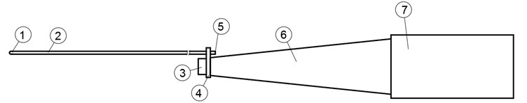
Tube shaped ultrasound wave guide wire with holes in the working end was offered as the alternative to the current patented invasive thrombosis treatment solutions. The principal scheme of the innovative waveguide is presented in Figs. 2 and 3.
Fig. 2Ultrasonic blood vessels cleaning device (cross-section)
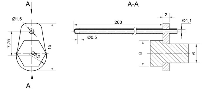
Fig. 3Ultrasonic blood vessels cleaning system, where: 1) waveguide hole, 2) tube-shaped waveguide, 3) fixing screw, 4) lug, 5) intake 6) concentrator, 7) transducer
The 260 mm length and 1,5 mm diameter wave guide wire is treated as invasive medical device and can be used to clean the inner walls of the artery, as well as the tool to destroy the thrombus and suck out the scurf of the blood clot at the same time.
To be able to provide a sufficient quantity of drugs to the needed place of the artery, tube-shaped wave guide wire was chosen. The drilled holes at the end of it works both, as intake and suction hole if needed.
Adequate feed of the drugs to the damaged place of the blood vessel is secured by unique design the of wire. The lug which allows the device to get attached to the concentrator is separated from the tube, through which the drugs are delivered. The construction is explained in Fig. 3. The diameter of the intake 1,1 mm.
Such construction of the wave guide wire allows to affect the ocludator not only mechanically but also by the flow of physiological fluid, provided through the intake, marked as number 5 in Fig. 3.
The dimensions of the waveguide were limited by normal diameter of lower human limb arteries. To be able to work even at the level of popliteal arteries, the wave guide diameter of 1,5 mm was chosen. Selection of other dimensions, as well as length optimization of the novelty design system are disclosed in upcoming European patent application “Tube shaped ultrasound wave guide wire for internal blood vessels cleaning” [12].
4. Computational simulation of waveguide wire
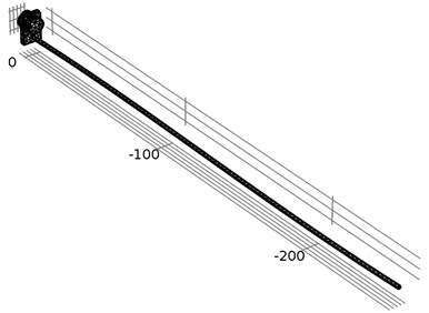
Finite element method (FEM) was used for the simulation of the tube-shaped ultrasound waveguide wire. Eigen frequency analysis was performed for the housing of waveguide as well as time-dependent simulation for a whole waveguide wire construction. COMSOL Multiphysics – a finite element analysis, solver and simulation software package for multi physics, engineering applications, and coupled phenomena, was used to model waveguide wire. A geometry and FEM meshing of the waveguide wire is given in Fig. 4. One should note, that the waveguide wire is slightly bent along axis. However, the analogous physical waveguide wire construction might have various imperfections and distortions which are not considered in theoretical computational model.
Fig. 4Illustration of geometry and FEM meshing of the waveguide wire and its housing
Solid mechanics physics interface was used to model behavior of the waveguide wire. Structural steel with density 7850 kg/m3, Young’s modulus 200e9 Pa, and Poisson’s ration 0.33 were applied to the body of tube-shaped ultrasound waveguide wire and its housing. The main equations governing finite element model for time-dependent study are as follows:
where denotes the displacement field; is time; is the material density; is the stress tensor; is an external volume force; is velocity. Environment temperature condition is 293.15 K and absolute pressure is 1 atm.
Fig. 5The location of investigated points of the waveguide wire in three different locations: the waveguide wire housing screw, the bottom of the waveguide wire housing, and the end of the waveguide wire
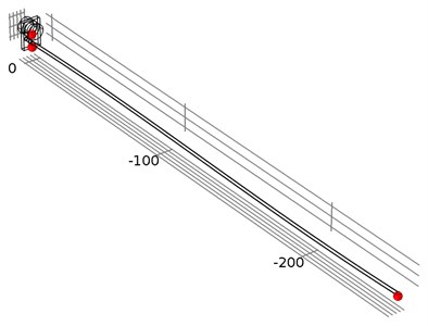
Fig. 6Computational results of the x, y, and z axis displacement on resonant frequency at the end point of waveguide
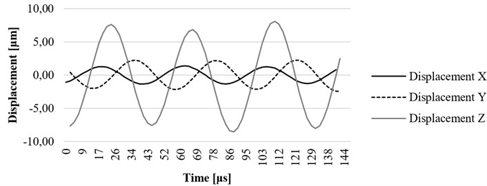
Fig. 7Computational results of the x, y, and z axis displacement on resonant frequency at the construction element (lug) of the ultrasound system
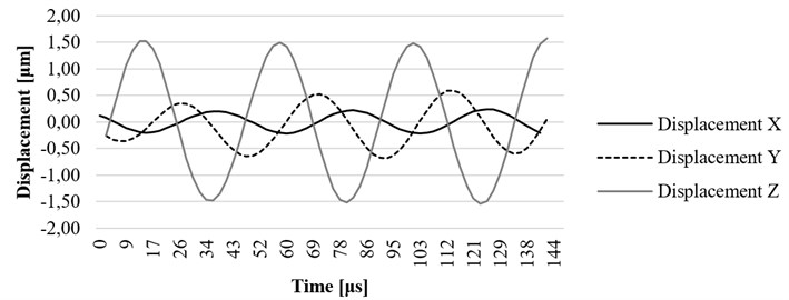
Fig. 8Computational results of the x, y, and z axis displacement on resonant frequency at the fixing element (screw) of the ultrasound system

-
Fig. 9The displacement field at t= 7.222941e-4, frequency 23089 Hz. Scaling factor 1000 is used to highlight displacements
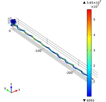
Eigen frequency analysis of the housing of waveguide wire was performed. The first Eigen frequency of the housing component is equal to 23089 Hz. For the time-dependent simulation of a whole waveguide wire construction a prescribed displacement was applied to the housing component along the y axis equal to:
where is frequency equal to 23089 Hz, and is amplitude equal to 1.4484 μm. Rayleigh damping was applied in the model with mass damping parameter 1115.88 and stiffness damping parameter 2.2371e-6.
Time-dependent simulation was performed in time interval . The location of displacement measuring points – the end of the waveguide wire, the waveguide wire housing screw, and the bottom of the waveguide wire housing are given in Fig. 5. The displacement values of the waveguide wire on resonant frequency are given in Fig. 6, Fig. 7 and Fig. 8 respectively to location points. Finally, the 3D representation is given in Fig. 9. One should keep in mind, that scale factor of 1000 is used to highlight the results as displacements of a few micrometers would not be visible otherwise.
5. Experimental research
To determine resonance frequency for the highest displacement toward axis, the experiments on the Polytec PSV 3D laser vibrometer experimental table were carried on. The experimental investigation setup is shown in Fig. 10 it consists of: 1 – Polytec PSV 3D laser vibrometer; 2 – ultrasound waveguide system; 3 – magnetic holder of transducer; 4 – anti-vibration table. To secure reflection of the laser beam from the tip of the waveguide the reflection film was glued on the tip. The mass of the glued reflection film is insignificant and the results of the experiment were not affected. Firstly, the FFT analysis was made to determine peaks of the system in frequency range between (15-30 kHz). Afterwards the biggest displacement toward axis was determined. To determine displacements when transducer was excited with working voltage, the peak was investigated in time scanning mode.
The experimental investigation was carried out in several different conditions and different points of interest. The waveguide was investigated in free conditions as shown in Fig. 10 and placed in tube which was filled with water. In both cases the displacement of the tip of the waveguide was measured. In other case, the screw of housing of waveguide and housing of the waveguide (lug) was investigated to determine the influence of housing (lug) to displacement of the waveguide.
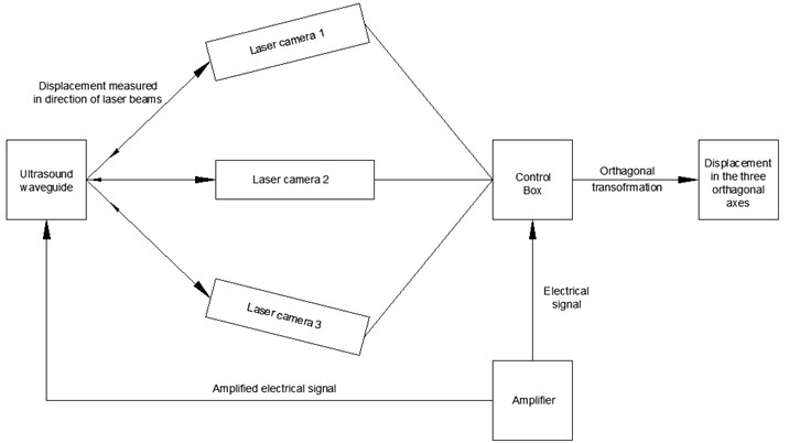
Fig. 10Experimental setup. 1) polytec machine (laser sources); 2) waveguide; 3) holder; 4) anti-vibration table
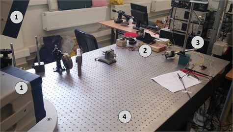
Fig. 11Polytec PSV 3D laser vibrometer experimental scheme
Ultrasonic blood vessels cleaning system was excited by periodic chirp type signal with amplitude of 10 volts and FFT analysis of tip of the waveguide was performed. The results have shown that highest displacements in axis occur at resonance frequency of 23.19 kHz with the amplitude of 21 nm.
The resonance frequency of 23.19 kHz was determined when ultrasonic blood vessels cleaning system was excited by sine signal with the amplitude of 100 V. Investigated tip of the waveguide provided the highest 7,02 micrometer displacement towards axis (Fig. 13).
Computational analysis and experiments revealed the elliptical movement of the tip of the wave guide. It was caused by the surface imperfections of the steel surface and the mechanical wave transmission through the threaded connection between the screw, connecting the waveguide to a concentrator and transducer. If compared to computational analysis, more sizeable displacement is noticed during the experiment while applying real conditions.
Fig. 12(FFT analysis of the tip of waveguide in the range of 15-30 kHz). Determining the resonance frequency for the best displacement on z axis
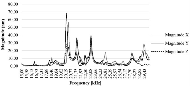
Fig. 13x, y, and z axis displacement on resonant frequency at the end point of waveguide
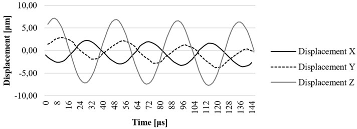
Fig. 14x, y, and z axis displacement on resonant frequency at the fixing element (screw) of the ultrasound system
The investigation of the housing screw and housing lug was performed to determine the influence of these parts to displacements of the waveguide. The excitation signal was the same as described in the section above. The results have shown that the displacement of the screw towards is 1.4 um (Fig. 14) and displacement of the housing end towards axis is 1.8 um (Fig. 15), therefore it could be said that the housing has impact on displacements of the tip of the waveguide towards axis.
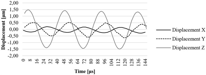
Fig. 15. , , and axis displacement on resonant frequency at the construction element (lug) of the ultrasound system
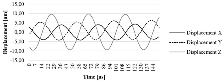
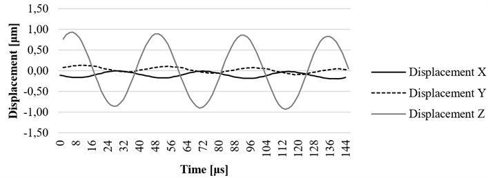
Fig. 16. , , and axis displacement on resonant frequency at the end point of waveguide filled with water
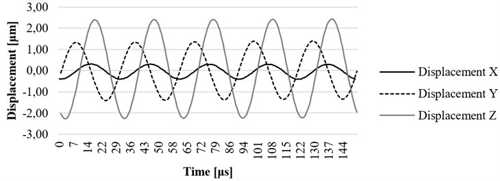
Fig. 17. , , and axis displacement on resonant frequency at the end point of waveguide filled with water, placed in the water-filled catheter
In Fig. 16 the experiment was made while the waveguide was filled with water. In this case, the maximum displacement of 11,02 μm was determined. The results gathered while waveguide was filled with water and placed in a tube which was also filled with water are shown in Fig. 17. In this case, maximum displacement of 2,1 μm was determined, the wave period was shortened by more than 1,5 times. The investigation also has shown that the waveguide is damped when it is excited in conditions which are very similar to its real working environment (surrounded by fluid inside the blood vessel). The experiment showed positive results to continue further investigation, including the computational analysis of newly designed ultrasound system in a real working environment.
6. Conclusions
Unique design ultrasound invasive blood vessel cleaning device was designed and constructed. It allows not only to suck out the scurf of the just destroyed blood clot but also provides the needed amount of medicine to the needed spot of the damaged blood vessel.
The computational simulation of tube-shaped ultrasound wave guide wire was performed. Eigen frequency analysis was done for housing of the waveguide. The first Eigen frequency of the housing component is equal to 23089 Hz. Time-dependent simulation for a whole waveguide wire construction and its displacements along all axis were calculated. The experimental research showed that resonance frequency of 260 mm length tube-shaped wave guide wire is 23190 Hz. It corresponds well with the results determined by the FEM model. At this resonance frequency, the largest displacement towards the z axis is equal to 7,02 μm.
The FFT analysis has shown very significant difference between displacement of the tip of the waveguide in different conditions. In free mode (in the air) the maximum displacement towards axis was 11,02 μm. While the waveguide was placed in the fluid-filled tube the displacement was almost 5 times smaller and reached only 2,1 μm. Further experimentation with the waveguide placed in a tube filled with different kinds of fluid is needed and is planned research.
It can be observed that displacement of a screw towards axis is 1.4 um and displacement of the housing lug towards the same axis is 1.8 um. Therefore, housing parts have significant impact on displacements of the tip of the waveguide towards the axis. Such phenomenon is very important for the efficiency of the waveguide in cardiovascular thrombosis treatment applications.
References
-
Li H., Horke S., Förstermann U. Vascular oxidative stress, nitric oxide and atherosclerosis. Atherosclerosis, Vol. 237, Issue 1, 2014, p. 208-219.
-
Alexopoulos N., Katritsis D., Raggi P. Visceral adipose tissue as a source of inflammation and promoter of atherosclerosis. Atherosclerosis, Vol. 233, Issue 1, 2014, p. 104-112.
-
Tzirtzilakis E. E. Biomagnetic fluid flow in an aneurysm using ferrohydrodynamics principles. Physics of Fluids, Vol. 27, Issue 6, 2015, p. 1-19.
-
Abdullah B. J. J., Mohammad N., Sangkar J. V., et al. Incidence of upper limb venous thrombosis associated with peripherally inserted central catheters (PICC). The British Journal of Radiology, Vol. 78, 2005, p. 596-600.
-
Yamagami T., Kato T., Iida S., Tanaka O., Nishimura T. Retrievable vena cava filter placement during treatment for deep venous thrombosis. The British Journal of Radiology, Vol. 76, 2003, p. 712-718.
-
Bubulis A., Jurėnas V., Minchenia V. T., Stepanenko D. A., Bobrovskaja A. I., Chizh D. V. Study of the process ot interaction between low-frequencyultrasound and biological tissue phantoms. Journal of Vibroengineering, Vol. 13, Issue 3, 2011, p. 586-589.
-
Bubulis A., Jurėnas V., Stepanenko D., Minchenya V. Effect of design of the distal part of wave guide concentrator on efficiency of destroying blood clots during ultrasound angioplasty. International Scientific Seminar, Science and Education, 2011, p. 11-14.
-
Tun C. Effektivnost vosstanovlenija prochodimosti porazhennix aterosklerozom arterij ultrazvukovimi volnovodami razlichnich modofikacij in vitro. BelMAPO, 2006, p. 21.
-
Siegal R. J., Gunn J., Ahsan A., Fishbein M. C., Bowes R. J., Oaukley D., Wales C., Steffen W., Campbell S., Nita H. Use of theraupeutic ultrasound in percutaneous coronary angioplasty. Experimental in vitro studies and initial clinical experience. Curculation, Vol. 89, Issue 4, 1994, p. 1587-92.
-
Peterson T., Pal D. Ultrasonic Resonator. US Patent No. US6617760, 2003
-
Nita H., Sarge J. Steerable Ultrasound Catheter. US Patent No. US7335180, 2008
-
Bansevičius R., Bubulis A., Jurėnas V., Minchenia V., Valaika M. Ultrasound Wave Guide Wire for Internal Blood Vessels Cleaning. EU Patent No. EP2065002, 2009.
About this article

This research is funded by Research Council of Lithuania, Project No. MIP-097/15.
