Abstract
Two-hammer synchronous vibration system which consists of two hammers is a complex electromechanical system with complex electromechanical coupling. In this paper, electromechanical coupling characteristics of this system are studied in detail using the methods of theoretical derivation, numerical simulation and experiment. The kinetic models of this system are established, and approximate expressions of electromechanical coupling strength are solved using periodic averaging method (PAM). Basic coupling rules and reasons are obtained. Subsequently, numerical simulation is carried out, and simulation results demonstrate the correctness of model and approach. After that, based on electromechanical coupling characteristics, compound synchronization error feedback and composite control based on inching control (CSEB-CCBIC) strategy and algorithm are proposed, and simulation results validated the effectiveness of the proposed strategy. Finally, experiments are carried out, and the results show that, speed and phase achieve synchronization quickly under the action of synchronization controller, which are agree well with theoretical and numerical results. The research conclusions and methods also provide theoretical foundations for multi-hammer synchronous vibration system and its synchronization control.
1. Introduction
The vibratory hammer driven by electromotor is widely used in construction engineering. The use of a single hammer is restricted by the limited power of electromotor in large pile foundation projects. Therefore, multi-hammer synchronous vibration system using multiple vibration hammers coordinated to work together is designed and applied to multiple projects in recent years. During the construction of Kansai international airport, eight 150 kw vibratory hammers with linkage shafts in series were used to vibrate and sink a large steel cylinder (23 m in diameter). Another such application was demonstrated for construction applications by a Chinese team, where four hydraulic pile hammers linked with bevel gears were used to sink a cylinder pile (13.5 m in diameter) [1]. The American Pile Driving Equipment Corp. used eight linked pile hammers while working on the man-made island project (Hong Kong-Zhuhai-Macao Bridge, China) [2]. In these engineering applications, the shaft coupling has been applied to connect the rotating shaft of each vibratory hammer. In this system, both phase and velocity of all vibratory hammers to be synchronized. However, a disadvantage of this method is the use of complex linkage structures [3], which can be easily damaged; meanwhile, the number of vibration hammer is also not easy to expand.
At present, there are several ways to synchronize the multi-hammer vibration system. One is mandatory synchronization method, shaft coupling mechanical mechanism is used to connect rotation axis of each hammer, realizing speed and the phase synchronization. The other synchronization method is vibration synchronization method, in this method, electromechanical coupling is used rightly. Researches have investigated the mechanism of the vibration synchronization, and self-synchronization phenomenon has been observed in many occasions [4, 5]. Blekhman et al. [6-8] proposed a definition to generalize synchronization and the basic synchronous vibration theory for a double vibration hammer. Inoue and Araki et al. [9] discovered three-octave synchronization for double motor driving vibrators. Wen et al. [10-14] established the synchronization condition of two vibratory hammers, and applied it to engineering successfully. But about this method, there are strict requirements on structure and dynamic characteristics of the mechanical system, and easy to out of step, thus it is not suitable for all mechanical systems. The third way is control synchronization. The working principle of this method is that, speed and phase of eccentric block are measured in real time, then speed and phase difference are eliminated by control method. This method was proposed by PVE Corp. (Holland) [3]. However, there are no subsequent reports and engineering applications so far. Bingham et al. removed the mechanical gear assembly between the eccentric masses and implemented a control system to realize synchronization of different eccentric masses [15]. Electromechanical coupling was discovered in this system, however, it was only regarded as a disturbance signal in the design of control algorithm. Actually, electromechanical coupling effect follows some rules. Hence, it is very meaningful to design synchronization control strategy and algorithm based on electromechanical coupling characteristics.
This work in this paper aimed to design an effective synchronization controller on the basis of solving electromechanical coupling characteristics of two-hammer synchronous vibration system. The paper is organized in seven sections. In Section 1, the brief introduction is given. In Section 2, the mathematical model of two-hammer synchronous vibration system are set up. The coupling strength expression and basic coupling characteristics are determined using an approximate analysis method in Section 3. Next, numerical simulation of the electromechanical coupling process is carried out in Section 4. In Section 5, the synchronous control strategy and algorithm are designed base on electromechanical coupling action, and the effectiveness is verified by simulation. In Section 6, experiments are carried out, and the effectiveness of designed synchronization controller is verified. In Section 7, a brief summary of the conclusions is given.
2. Mathematical model
2.1. Synchronous description of multi-hammer vibration system
Synchronization refers to the relative relationship between two or more than two physical variables that vary over time. For a single vibration hammer, the relationship between rotating speed and phase angle of eccentric block can be expressed as:
where is initial phase.
For the multi-hammer vibration system, the synchronization can be described by rotating speed and phase of eccentric block. When phase angle difference of each eccentric block of vibration hammer is kept constant, indicating a synchronous vibration state of multi-hammer vibration system. Especially, when the phase difference is equal to zero, the maximum excitation force is synthesized.
2.2. Dynamic equation of two-hammer synchronous vibration system
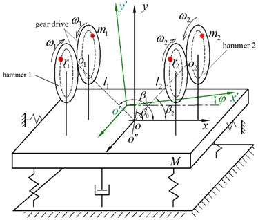
The dynamic model of two-hammer synchronous vibration system is illustrated in Fig. 1. In the Fig. 1, is absolute coordinate system, is moving coordinate system, is angle between and , is midpoint of rotating center of eccentric masses of hammer, and , , is angular velocity of eccentric mass, is mass of the eccentric block , is rotation angle of rotor, is eccentric distance of the eccentric block .
Fig. 1Model of two-hammer vibration system
Taking , , , and as generalized coordinates, the kinetic energy , potential energy and generalized force of vibration system are written in the generalized coordinates as following:
where is mass of the hammer (not including eccentric block), is moment of inetia of hammer, is moment of inertia of the rotor, , and are the stiffness coefficient in the direction of , and respectively, , and are damping coefficient in the direction of , and respectively. is electromagnetic torque of the motor .
Furthermore, substituting Eq. (2)-(4) into Lagrange equation, the dynamic equation of two-hammer vibration system can be established as:
2.3. Mathematical models of three-phase asynchronous motor and inverter
Usually, the electrically actuated vibratory hammer is driven by three-phase asynchronous motor. Therefore, according to [16], the expressions of flux of motor, voltage equations, and electromagnetic torque in two-phase rotating coordinate system can be written as:
where and are stator terminal voltage, and are stator terminal current, and are rotor terminal current, and are stator terminal flux, and are rotor terminal flux, and are resistance of stator and rotor, and are inductance of the stator and rotor, is mutual induction of the stator and rotor, is difference between rotor flux rotation angular velocity and rotor rotation angular velocity, is synchronous rotation angular velocity, is angular velocity of rotor, is coefficient of drag torque, , , and are electromagnetic torque, friction torque, load torque of motor, respectively, is pole pairs of motor, is moment of inertia of motor.
In order to simplify the model while maintaining sufficient accuracy, the inverter model choose the basic PI (proportional integral) controller for speed feedback, the transform expression of controller can therefore be expressed as:
where is reference output torque, is setting speed, is measured speed, and are basic control parameters for PI controller.
Eq. (5) to Eq. (10) are the mathematical models of two-hammer synchronous vibration system. It is obvious that parameters in these expressions are coupled. Moreover, the equation of motor is nonlinear and complex, so it is hard to find out an analytical solution.
3. Approximate analysis of electromechanical coupling strength
In this study, an approximate solution method is adopted, it can be described as follows: by the approximate solution of Eq. (5), load torque equations of driving motors are obtained, then electromechanical coupling characteristics are analyzed according to the working characteristics of motor. Namely, the torque change rules of the two hammer motors is analyzed to reveal the electromechanical coupling property.
In order to solve Eq. (5), the periodic averaging method(PAM) is used. The core idea of PAM is to solve the average value of the load torque of motor in a vibration period. We assume that the average phase angle of the eccentric blocks of two hammers is , phase difference between the hammers is , and average rotating speed of motors is . Then, the relationship between the phase angles can be given by the following expressions:
here, we assume that the fluctuation coefficient for the average rotating speed is , while that of instantaneous phase difference relative to the average rotating speed is (note that and are the functions of time, and their values are much less than 1), thus:
From Eq. (11) and Eq. (12), instantaneous rotation velocity of two motors can be written as:
From Eq. (13), instantaneous accelerated velocity of two eccentric blocks can be written as:
Substituting Eq. (13) and Eq. (14) into Eq. (5), the following equations are obtained:
where , , , .
Since and are slowly varying components relative to the average velocity displacement response of the system can be replaced by the average rotating to obtain an approximation. According to the superposition principle of linear equations, solution of Eq. (15) can be expressed as:
where:
Hence, the fourth term of Eq. (5) can be changed into the following form:
where is defined as vibration resistance moment of motor, and is defined as vibration inertia moment of motor. So the load torque of motor is composed of and .
Additionally, the first and second derivatives of Eq. (16) with the minor terms omitted, the following equations can be obtained:
By substituting Eqs. (18)-(21) into Eq. (17), and integrating over , average value within a vibration period is obtained. Average value of and can be expressed as:
where, , , is average vibration resistance moment of the motor, is average vibration inertia moment of the motor.
From Eq. (22) and Eq. (23), over one period, average load torque of Motor 1 and Motor 2 can be obtained as:
where is defined as average load torque of the motor 1, and is defined as average load torque of the motor 2.
From Eq. (17), the absolute value of load torque difference of the two motors can be expressed as:
According to working characteristics of three-phase asynchronous motor, with increase of load torque, the motor slip ratio increases, so the rotation speed decrease. Moreover, the variation of motor speed will directly affect the vibration state of multi-hammer synchronous vibration system. Hence, electromechanical coupling strength of the system is defined as:
From Eq. (24), we can see that the load torques of the two motors change in opposite directions, and are related to multiple parameters, such as displacements in and directions, installed distance and eccentric distance of hammers, phase difference, angular velocity, angular acceleration and soil parameter. According to the above analysis, it can be inferred that the vibration system and dynamic system are mutually dependent and affect each other through load torque, while the load torque in turn affects rotating speed of asynchronous motors.
According to the Eq. (25) and Eq. (26), we can see that if the mechanical properties of motor are rigid, namely motor speed is not easily affected by the load torque, so electromechanical coupling strength will be small. When phase difference is , electromechanical coupling strength is the largest, and when the phase differenceis zero, the electromechanical coupling strength is zero.
Eq. (24) shows that the value and positive of directly determine electromechanical coupling characteristics. If the vertical vibration is dominant, . Furthermore, if excitation frequency in low frequency region, resonate region, and high frequency region, the rang of phase angle between excitation and response is 0 to , , and to , respectively. Similarly, the influence law of direction can be obtained. Moreover, according to working characteristics of motor, the basic electromechanical coupling rules can be obtained through qualitative analysis, as shown in Table 1.
Table 1Basic electromechanical coupling rules
Vibrational state | ||
Excited frequency | Vertical vibration is dominant ( direction) | Deflection vibration is dominant ( direction) |
Low frequency region | ||
Resonate region | ||
High frequency region | ||
In summary, the result of electromechanical coupling is that the load torque of motor is re-allocated and a new balance is achieved. According to Table 1, the change laws of load torque can be obtained. For example, assuming that vibratory hammer works in the high frequency region, and vertical vibration is dominant, the load torque due to electromechanical coupling can be expressed in Table 2.
Table 2Effect of electromechanical coupling on torque of motor
0 | ||||||||
0 | , is maximum | 0 | , is minimum | |||||
0 | , is minimum | 0 | , is maximum |
4. Numerical simulation of coupling process
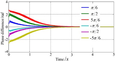
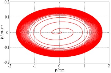
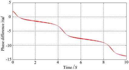
The simulation model is established according to Eqs. (5)-(10), and the electromechanical coupling process is obtained by numerical simulation using previously mentioned ideal conditions. The software used for developing the simulation programming is MATLAB/Simulink. During simulation, the initial phase difference is set as . Results obtained when the rotating speeds of the two hammer motors are equal, shown in Fig. 2.
Fig. 2Electromechanical coupling process
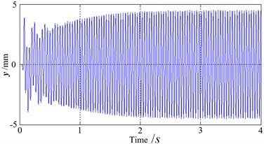
a) Amplitude at direction
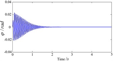
b) Twist angle
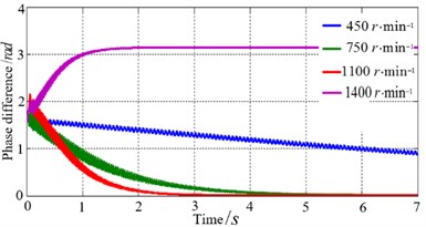
c) Phase difference at different motor speed
d) Phase difference at different initial phase difference
e) Kinematics phase diagram
f) Speed difference of motors is big
It can be seen that the phase difference gradually converges to zero when motor speed is lower, and the higher rotation speed, the larger convergence rate. When the rotation speeds are higher than a certain level that relevant to stiffness and damping coefficient, phase difference tends to . Namely, phase difference tends to zero in the low frequency region, and phase difference tends to in high frequency region, as shown in Fig. 2(c). As the phase difference tends towards zero, the twist angle gradually attenuates and stabilizes around zero. Also, amplitude in the direction gradually stabilizes, as shown in Fig. 2(a)and Fig. 2(b). The kinematics phase diagram in y direction is shown in Fig. 2(e). Fig. 2(d) shows simulation results in different initial phase differences, it can be seen that for a smaller the initial phase difference, convergence rate is larger. As shown in Fig. 2(f), when speed difference of two motors is big (740 r/min, 760r /min), the electromechanical coupling effect is very weak, so self-synchronization cannot be observed. The simulation results agree well with the Table 1.
5. Synchronization control strategy and algorithm
5.1. Synchronization control strategy
According to Eq. (1), speed synchronization is the precondition of phase synchronization control. Phase difference can only be adjusted through the speed of motor. It is meaningless to pursue phase synchronization when there is big rotate speed difference. Therefore, the basic principle of synchronous control of multiple vibratory hammers is: a real-time detection on speed and phase of eccentric bloke of vibratory hammers is implemented and phase pursuit or waiting is accomplished through fine adjustment of speed based on speed synchronization or near synchronization. The designed basic control strategy is shown in Fig. 3.
As show in Fig. 3, a speed threshold is set. When speed difference is exceed , the speed controller will be started to run and the phase controller will be closed. Speed will be adjusted quickly, aiming to reduce speed difference. When rotate speed difference is smaller than , the phase controller is started to run and the speed controller is closed, phase difference is eliminated. The phase controller will be closed after phase difference satisfies the control objective. Phase synchronization is based on speed synchronization and is affected by strong electromechanical coupling effect. Improper control strategy will cause frequent switchover between phase controller and speed controller, failing to achieve both speed and phase synchronization.
Fig. 3Synchronization control strategy
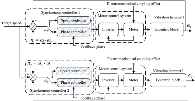
5.2. Speed synchronization control strategy and algorithm
Speed synchronization is the basis and guarantee of phase synchronization, small fluctuations in speed will bring large fluctuations in phase, so speed synchronization control algorithm is vital. At present, master-slave(MS) control is the most common synchronous control strategy [17, 18]. It chooses one hammer as the master and the rests as the slave vibratory hammers. State of slave vibratory hammers obeys to state of the master. However, speed of slave vibratory hammers will change when speed of master changes because of external disturbance. Therefore, master-slave control is not the optimum control strategy.
In this paper, compound synchronization error feedback(CSEB) control strategy is designed for speed synchronous control, as shown in Fig. 3. Suppose the reference speed is , and speed of motor is , 1, 2, so the tracking error is defined as:
Also, the synchronization error is defined as:
The speed synchronous performance is described with the tracking error and synchronization error, so the compound synchronous error can be expressed as:
where is correction coefficient.
It is clear that the speeds of all hammers will be adjusted if one of hammer is disturbed, thus it is beneficial for quacking the response of speed synchronous controller. Based on compound synchronous error , the PID (Proportion-Integral-Derivative) controller [19] is adopted, and it can be expressed as:
5.3. Phase synchronization control strategy and algorithm
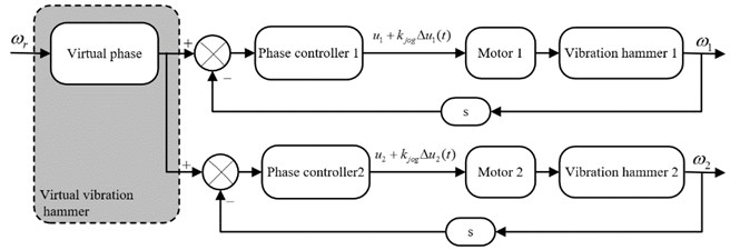
Actually, phase synchronization is the position synchronization of eccentric block. According to Table 1 and Table 2, the motor shafts are driven by driving or resistance torque under electromechanical coupling effect. Moreover, vibration hammer is a large inertia system, if phase control method is improper, it is likely to overshoot. Based on these reasons, we design an inching control strategy based on virtual phase, shown as in Fig. 4. It simulates a virtual phase signal using hardware and software according to the setting speed signal. Phase controller makes real-time collection of phase signal and virtual phase signal. The phase difference is gained by taking the virtual phase signal as reference, which is used for fine adjustment of motor speed to realize synchronous phase control of these vibratory hammers. The virtual phase signal changes continuously and won’t be interfered by external environment. It can improve the stability of phase synchronization control system.
Fig. 4Phase synchronous control strategy
In order to avoid overshooting, inching control method is designed. The core idea of this method can be summarized as “adjusting, waiting, then checking”. Suppose the controlled quantity of the th hammer when the control system switches to phase synchronous controller is . Controlled quantity of the th vibratory hammer can be gained from:
where is control increment, is inching control coefficient, it can be expressed as:
where is control period, and is inching period, .
The control process can be described as follows: in one control period, the controlled quantity calculated from phase control algorithm acts for a period of time (determined by ) and then return to , then wait for full system response. Next, speed difference and phase difference are detected again and then enter into the next control period. The inching control idea is very similar with the control behavior of human being, and it is very appropriate for high-speed rotating and big inertial system such as vibratory hammer.
Since electromechanical coupling effect between hammers will drive or hinder torque of motors, coupling effect on control system must be considered. For this reason, compound control strategy is designed. This control algorithm is composed of basic controlled quantity () and additional controlled quantity (). Thus, the controlled quantity can be described as:
where and are proportionality coefficients.
is calculated from conventional PID control algorithm, and the function of is to eliminate static phase difference, while is to eliminate or reduce the influence of coupling effect on phase difference.
As mentioned in the above Section 3, we can see that, the electromechanical coupling characteristics are obtained by using approximate solution and qualitative analysis method, and these characteristics can be described by some rules, as shown in Table 2. Furthermore, as shown in Eq. (5) to Eq. (10), the mathematical models of controlled object are complex and nonlinear. Hence, the fuzzy controller is more suitable for this system. The fuzzy rules are designed according to the laws of electromechanical coupling, and then control quantity is calculated through defuzzification.
Phase synchronization error can be written as:
So denotes phase equality, denotes phase lead, and denotes phase lag. According to constraint between rotate speed difference and phase difference, two rules for entering into the fuzzy controller are:
Taking phase difference and its rate of change as variables to design fuzzy controller. According to Table 1, domain of is divided into , and the domain of is divided into . Domain of output linguistic variable is divided into . Linguistic variables of , and can be described as:
where , , , , , , , , represents negative big, negative much big, negative moderate, negative small, zero, positive small, positive moderate, positive much big and positive big.
As shown in Fig. 5, the membership function is designed. Here, we define , , and as the degree of membership of , , , respectively. Based on Table 1 and Table 2, the fuzzy rules are designed, shown as in Table 3. Moreover, the control rules are generally expressed in the form as “if..., then...”, for example, one of the most important rules is: if is and is , then is .
Fig. 5Membership function
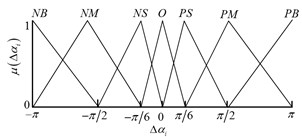
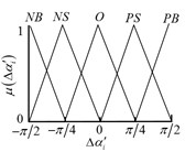
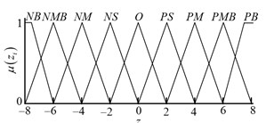
Table 3Fuzzy control rules
NB | NM | NS | O | PS | PM | PB | |
NB | NMB | NB | NB | NS | PM | PS | PS |
NM | NM | NB | NMB | NS | PM | PM | PS |
O | NM | NMB | NM | O | PS | PM | PM |
PM | NS | NM | NS | PS | PS | PMB | PMB |
PB | NS | NS | O | PS | O | PMB | PMB |
Based on fuzzy relation, the reasoning results in each rules can be write as:
where, and are the control inputs, is the operation of fetching mininum.
So the comprehensive reasoning result can be expressed as:
where, is the operation of fetching maximum.
The center of gravity method is used for defuzzification in this control system, so can be obtained as follows:
where, is ratio coefficient.
The composite control based on inching control (CCBIC) can reduce or eliminate the effect of electromechanical coupling on motor torque, which improves control precision of phase synchronization and avoids overshoot effectually.
5.4. Simulation
Simulation study on control strategy and algorithm can be implemented by adding control algorithm model into the electromechanical coupling numerical simulation model. The initial speeds of all hammers are set to 750 r/min, and the initial phase difference is set to . As comparison, four control strategies (MS-CCBIC, MS-PID, CSEB-PID and CSEB-CCBIC) are adopted for simulation. The simulation results are shown in Fig. 6. It is observed that synchronization control could eliminate fixed phase difference brought by electromechanical coupling, and the “CSEB-CCBIC” control strategy which fully considering electromechanical coupling characteristics has better control effects, such as shorter response time, smaller overshoot and fluctuations.
Moreover, in order to verify the disturbance resistance of these four control strategies, we assume that initial speeds 750 r/min, and motors speed are suddenly set to 740 r/min, 750 r/min at 5 s. In this case, simulated phase difference curves are shown in Fig. 6(b). Obviously, the proposed “CSEB-CCBIC” control strategy can achieve the desirable performance response. To sum up, viewed from response time, overshooting and disturbance resistance, the “CSEB-CCBIC” control strategy is better than rest control strategies. The simulation results verify the effectiveness of designed speed and phase synchronization controller.
Fig. 6Simulated results of phase synchronization control under electromechanical coupling
a) Control synchronization process
b) Phase difference after rotate speed disturbance
6. Experiment
To verify the correctness of electromechanical coupling characteristics and effectiveness of the synchronization control strategy and algorithm, an excitation system consisting two vibratory hammers is chosen for test. The power of hammer motor is 90 kw, and the parameters of steel pipe pile are: outer diameter is 1450 mm, wall thickness is 22 mm, length is 9.8 m, and weight is 7700 kg. Experimental device and testing site are shown in Fig. 7.
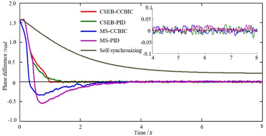
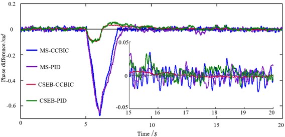
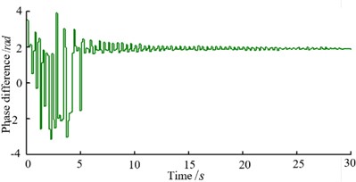
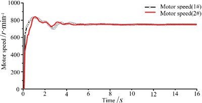
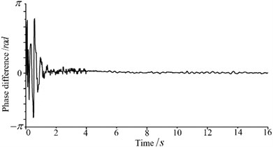
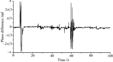
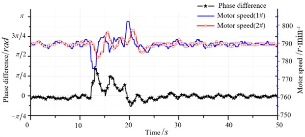
Experimental results are shown in Fig. 8. Fig. 8(a) illustrates the process of self- synchronization, it can be seen that phase difference tends to be stable under the action of electromechanical coupling. Fig. 8(b) is speed synchronization curve and Fig. 8(c) is phase difference curve, we can see that two vibratory hammers achieve speed and phase synchronization quickly and phase difference tends to zero, which lead to the maximum synthesis of the excitation force and beneficial to piles sinking. Fig. 8(d) is the measured phase difference curve when rotate speed of NO. 1 hammer is change suddenly during pile sinking. Phase difference fluctuates and then recover synchronous quickly, it is observed that proposed synchronization control strategy and algorithm have good robustness. Due to complexity of “hammer-pile-soil” dynamic response, electromechanical coupling of the system becomes complicated and unpredictable. Therefore, phase difference makes small fluctuation during synchronization, but still maintain good synchronous state. Fig. 9 shows speed and phase difference after disturbance during pile sinking. When motor speed of NO. 1 hammer is changed, synchronization controller could eliminate rotate speed difference quickly under the guarantee of a small phase difference fluctuation. It can be indicated that the proposed control algorithm has favorable synchronization performance and strong robustness.
Fig. 7Experimental device
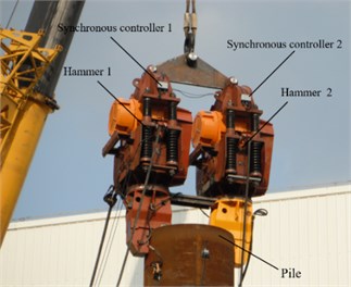
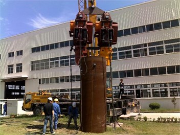
Fig. 8Synchronization control results
a) Self-synchronization process
b) Speed synchronization
c) Phase synchronization
d) Recovery synchronization after speed changes
Fig. 9Synchronous control curve after disturbance
According to the experiment results, phase and speed of hamers are monitored by the designed synchronization controller, which could maintain phase difference at zero. In this way, exciting forces of two vibratory hammers collaborate to maximum. Thus, the engineering application of this system is very wide.
7. Conclusions
There are complicated electromechanical coupling relationships in the two hammers excitation system. In this study, the dynamics model of this system and the motor model are established, and then electromechanical coupling intensity is get through periodic average method, the basic coupling rules and influencing factors are obtained. The result of electromechanical coupling is redistribution and balance of the torque of motor. The electromechanical coupling process is gained through numerical simulation, which validates the correctness of theoretical derivation. Synchronization control strategies and algorithm are designed for two hammers. Based on electromechanical coupling characteristics, the “CSEB-CCBIC” synchronization control strategy and algorithm is proposed. It could quickly eliminate fixed phase difference brought by electromechanical coupling and realize speed and phase synchronization. The effective of this control strategy is verified by numerical and experiment results. The two vibratory hammers synchronous system could realize the maximum combination of exciting forces, which could solve the problem of limited power of single electrically actuated vibratory hammer. Also, research results provide references for synchronization control of multiple hammers system.
References
-
Yuan M. Q., Xu W. H., Li Y. Q. Study and application of vibratory sinking equipment and technology for steel cylinder with large diameter. Construction Machinery, Vol. 11, Issue 2, 2004, p. 45-48.
-
Yin H. Key technologies applied in design and construction of artificial islands and immersed tunnel of Hong Kong-Zhuhai-Macau Bridge (HZMB) project. Tunnel Construction, Vol. 34, Issue 1, 2014, p. 60-66.
-
Fan Q. J. Synchronization of large hydraulic vibrators when working together. China Harbour Engineering, Vol. 34, Issue 2, 2003, p. 1-4.
-
Djanan Nanha, Nbendjo Nana, Woafo P. Self-synchronization of two motors on a rectangular plate and reduction of vibration. Journal of Vibration and Control, Vol. 21, 11, p. 2114-2123.
-
Li X. H., Chen S., Liu J. Harmonic vibration synchronization analysis of nonlinear vibration system based on frequency catching phenomenon. Journal of Mechanical Engineering, Vol. 50, Issue 3, 2014, p. 100-107.
-
Blekhman I. I., Fradkov A. L. Self-synchronization and controlled synchronization: general definition and example design. Mathematics and Computers in Simulation, Vol. 58, Issue 4, 2002, p. 367-384.
-
Blekhman I. I., Fradkov A. L. On self-synchronization and controlled synchronization. Systems and Control Letters, Vol. 31, Issue 1, 1997, p. 299-305.
-
Blekhman I. I. Selected Topics in Vibrational Mechanics. World Scientific, Singapore, 2004.
-
Balthazar M., Felix J. L., Brasil R. Short comments on self-synchronization of two non-ideal sources supported by a flexible portal frame structure. Journal of Vibration and Control, Vol. 10, Issue 12, 2004, p. 1739-1748.
-
Zhao C., Zhao Q., Gong Z., Wen B. Synchronization of two self-synchronous vibrating machines on an isolation frame. Shock and Vibration, Vol. 18, Issue 1, 2011, p. 73-90.
-
Kong X., Zhang X., Chen X., Wen B. Synchronization analysis and control of three eccentric rotors in a vibrating system using adaptive sliding mode control algorithm. Mechanical Systems and Signal Processing, Vol. 72, Issues 73-5, 2016, p. 432-450.
-
Zhang X., Wen B., Zhao C. Experimental investigation on synchronization of three co-rotating non-identical coupled exciters driven by three motors. Journal of Sound and Vibration, Vol. 333, Issue 13, 2014, p. 2898-2908.
-
Zhao C. Y., Zhang Y. M., Wen B. C. Synchronization and general dynamic symmetry of a vibrating system with two exciters rotating in opposite directions. Chinese Physics B: English, Vol. 19, Issue 3, 2010, p. 14-20.
-
Zhang X. L., Zhao C. Y., Wen B. C. Theoretical and experimental study on synchronization of the two homodromy exciters in a non-resonant vibrating system. Shock and Vibration, Vol. 20, Issue 2, 2013, p. 327-340.
-
Bingham C. M., Stone D., Howe D. Amplitude and frequency control of a vibratory pile driver. IEEE Transactions on Industrial Electronics, Vol. 47, Issue 3, 2000, p. 623-631.
-
Zanasi R., Azzone G. Complex dynamic model of a multi-phase asynchronous motor. IEEE International Conference on Electrical Machines, Vol. 413, Issue 1, 2010, p. 1-6.
-
Nakamura M., Goto S., Kyura N. Master-slave synchronous positioning control. Lecture Notes in Control and Information Science, Vol. 300, Issue 2, 2004, p. 149-168.
-
Hartani K., Maata F., Merah A. Sensorless master-slave direct torque control of permanent magnet synchronous motors based on speed MRAS observer in electric vehicle. Research Journal of Applied Sciences Engineering and Technology, Vol. 23, Issue 7, 2014, p. 5034-5048.
-
Silva G. J., Datta A., Bhattacharyya S. P. PID Controllers for Time Delay Systems. Boston, Birkhauser, 2005.
About this article

The authors gratefully acknowledge that the work was supported by the National Natural Science Foundations of China (No. 51505290).
