Abstract
The influence of the control characteristics of a direct torque control (DTC) motor on the load sharing behavior of a torque coupling gear set is studied by establishing a dynamic model of a multi-motor torque coupling system. The effects of run-out errors of the pinions of the torque coupling gear set on the powertrain are analyzed under steady operating conditions. The difference in rotational speed among the pinions becomes apparent, and the load sharing behavior deteriorates when there are run-out errors. The relationship between the control characteristics and load sharing behavior is studied. The difference in rotational speed decreases and the load sharing behavior improves as proportional and integral gains of the speed controller increase.
1. Introduction
The power of several motors in a multi-motor torque coupling system is coupled to a torque coupling gear set. The multi-motor torque coupling system features a small volume with high reliability. The load sharing behavior of the torque coupling gear set should be considered as it is a type of split drive.
Wei et al. [1] established a dynamic model for a torque coupling gear set. They analyzed the vibrational displacement of gears and the effects of rotational speed on the load sharing behavior. Yu et al. [2] also established a dynamic model for a torque coupling gear set and proposed a load sharing index by analyzing the Floquet multipliers of the model. They analyzed the effects of bearing stiffness of the pinions, mounting locations of the pinions, size of the gears and the rotational speed on the load sharing index. Bai et al. [3] concluded that the load sharing behavior is bad at low rotational speed after analyzing effects of rotational speed on load sharing behavior. Shu et al. [4] analyzed the effects of synchronization of the input torque on the load sharing behavior of a torque coupling gear set. Li et al. [5-8] analyzed the effects of backlash, static transmission errors, inertia of gears and load torque on vibrational displacement of gears in a torque coupling gear set. Zhang et al. [9] analyzed the effects of mesh stiffness parameters on the instability of a torque coupling gear set. The mesh stiffness parameters include mesh frequencies, stiffness variation amplitude and mesh phasing. Zhang et al. [10] proposed a finite element model of a cutterhead driving system of a tunnel boring machine. The system includes a torque coupling gear set. They analyzed the vibrational displacement of a pinion and an inner race of a main bearing in the torque coupling gear set under impact conditions.
Kahraman et al. [11-13] analyzed the effects of piloting conditions, the number of planets, manufacturing and assembling errors, and load torque on the load sharing behavior of the planet gear sets. They proposed a method to measure the load sharing behavior of planet gear sets by measuring the bending stresses of pinion pins and verified the relationship between the load sharing behavior and the pinion-pin position errors. Singh [14, 15] proposed a physical explanation to the unequal load sharing phenomenon of planet gear sets that is caused by pinion-pin position errors by analyzing float and deformation. Then he concluded features of the load sharing behavior of planet gear sets with 3 to 7 planets.
Lumped mass models and finite element models of torque coupling gear sets were established in order to study dynamic behavior. This includes the effects of configuration of gear sets, internal excitations, rotational speed, and load torque on load sharing behavior. However, these parameters cannot be changed when a torque coupling gear set is under operating conditions. The parameters cannot be used in a controller designed to improve the performance of the torque coupling gear set. In multi-motor torque coupling systems, the inputs are independent from each other. Therefore, it is possible to improve the performance of the system by regulating the characteristics of the motors. In this study, a dynamic model of a multi-motor torque coupling system, composed of three DTC motors and a torque coupling gear set, is established. The relationship between the control characteristics of the DTC motors and the load sharing behavior of the torque coupling gear set is studied under steady operating conditions.
2. Dynamic model of multi-motor torque coupling system
A prototype of a multi-motor torque coupling system is shown in Fig. 1.
The powertrain is composed of three motors, a torque coupling gear set, and a planetary gear set. The motors are three-phase induction motors and are controlled by direct torque controllers. The torque coupling gear set is an external spur gear set, composed of three input pinions and one output gear. It has three paths to transmit power. The power of the motors is coupled to the torque coupling gear set.
Fig. 1Prototype of multi-motor torque coupling system. (1 – motor; 2 – torque coupling gear set; 3 – planetary gear set)
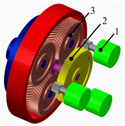
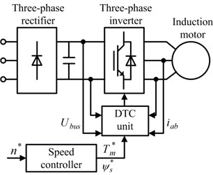
Fig. 2Schematic diagram of DTC motor
2.1. Dynamic model of DTC motor
The schematic diagram of a DTC motor is shown in Fig. 2.
The system is composed of a three-phase rectifier, a three-phase inverter, an induction motor, a speed controller, and a DTC unit. The input voltages influence the electromagnetic torque of the induction motor. These input voltages are decided by the states of the three-phase inverter. The DTC unit controls the states of the three-phase inverter based on the inverter D.C. input voltage , the stator current , the electromagnetic torque reference , and the flux reference . Therefore, the DTC unit controls the electromagnetic torque of the induction motor. The dynamic model of a DTC motor in the Simulink Library is used for this study.
2.1.1. Model of speed controller
The speed controller derives the electromagnetic torque reference based on errors between the rotational speed reference and the actual rotational speed of the motor. A proportional-integral (PI) controller is used in the speed controller:
where ; is proportional gain; is integral gain; is a rotational speed error; is the rotational speed reference; and is the actual rotational speed.
2.1.2. Dynamic model of motor
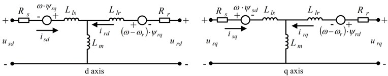
The equivalent circuit of the motor in d-q frame is shown in Fig. 3.
Fig. 3Equivalent circuit of the motor
The dynamic model of the motor is given as follows:
where , . and are the - and -axis stator voltages, respectively; and are the - and -axis rotor voltages, respectively; is a stator resistance; is a rotor resistance; and are the - and -axis stator currents, respectively; and are the - and -axis rotor currents, respectively; and are the - and -axis stator flux linkages, respectively; and are the - and -axis rotor flux linkages, respectively; is angular velocity of the d-q frame; is electrical angular velocity; is stator leakage inductance; is rotor leakage inductance; is magnetizing inductance; is total stator inductance; is total rotor inductance.
2.1.3. Model of DTC unit
The electromagnetic torque is a function of the stator flux linkage and the rotor flux linkage:
The function between the stator flux linkage and the voltage space vector is represented in Eq. (5) when neglecting the stator resistance voltage drop:
where is electromagnetic torque; is the number of poles; is a stator flux linkage; is a rotor flux linkage; is the angle between the stator flux linkage and the rotor flux linkage; is a stator voltage; is time.
The rotor flux linkage changes more slowly than the stator flux linkage owing to a large rotor time constant. Therefore, the angle can be controlled by changing the direction of the stator flux linkage. As a result, the electromagnetic torque can be controlled by choosing a proper voltage space vector.
The schematic diagram of the DTC unit is shown in Fig. 4.
Fig. 4Schematic diagram of the DTC unit
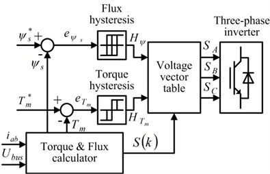
The stator flux linkage, the electromagnetic torque, and that represents which sector the stator flux linkage is in, are derived by the torque and flux calculator based on the stator currents and the inverter D.C. input voltage. The hysteresis comparators produce the required change in stator flux linkage and electromagnetic torque, and the voltage vector table selects the required inverter state. This allows it to provide a voltage vector that will change the stator flux linkage and electromagnetic torque as required.
2.2. Dynamic model of gear train
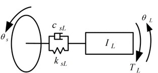
The load sharing behavior of the torque coupling gear set is considered here. Therefore, a lumped mass model of the torque coupling gear set is established, with the other parts behind it being simplified as an equivalent moment of inertia referred to the sun gear of the planetary gear set. The analytical model of the torque coupling gear set is shown in Figs. 5, 6.
Fig. 5Models of input and output shafts
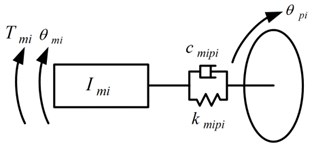
a) Input shafts
b) Output shaft
The relative gear mesh displacement along the line of action between the pinion- (where 1, 2, or 3) and the gear is defined as:
The dynamic mesh force of each path is defined as:
The dynamic model of the gear train is given as follows:
where the displacement vector and the mass matrix are defined, respectively, as follows:
Fig. 6Model of the torque coupling gear set
The damping and stiffness matrices are given as follows:
The forcing term is given as follows:
where and are the base circle radii of the pinion- and gear, respectively; , , , and are the angular displacements of the rotor-, pinion-, gear and equivalent link, respectively; and are the vibrational displacements of the pinion- in the directions of the - and -axis, respectively; and are the vibrational displacements of the gear in the directions of the - and -axis, respectively; is the operating pressure angle; is the phase angle of pinion-, where ; is the static transmission error; is the run-out error of pinion-; and represent the mesh stiffness and damping between the pinion- and gear, respectively; and represent the torsional stiffness and damping of the input shaft-, respectively; and represent the torsional stiffness and damping of the output shaft, respectively; and represent the support stiffness of the pinion- in the directions of the - and -axis, respectively; and represent the support damping of the pinion- in the directions of the - and -axis, respectively; and represent the support stiffness of the gear in the directions of the - and -axis, respectively; and represent the support damping of the gear in the directions of the - and -axis, respectively; , , , and are the mass moments of inertia for the rotor-, pinion-, gear and equivalent link, respectively; and are the masses of the pinion- and gear, respectively; is electromagnetic torque of motor-; is the load torque applied to the equivalent link.
The time-varying mesh stiffness is defined using a seven-term Fourier series:
where is the mean value of the time-varying mesh stiffness; is the amplitude of the th harmonic term; is the base pitch of the pinion.
The mesh damping is defined as follows:
where is the damping ratio.
The static transmission error is also defined using a seven-term Fourier series:
where is the mean value of the static transmission error; is the amplitude of the th harmonic term.
The run-out error of the pinion- is defined as follows:
where is the amplitude of the run-out error of the pinion-; is angular velocity of the pinion-; and is an initial position angle of the run-out error of the pinion-.
2.3. Load sharing coefficient
The load sharing coefficient is defined as the ratio of the dynamic mesh force to the static mesh force which would be transmitted by the same gear mesh under ideal conditions [10]:
3. Results and discussion
3.1. Parameters of powertrain
The multi-motor torque coupling system is used in a longwall shearer’s cutting system. The parameters of the gear train and motors are listed in Table 1 and Table 2, respectively.
Although the model numbers of the motors are same, the parameters are different owing to machining and assembly errors. The difference between the actual and rated value is less than 1 % of the rated value.
Table 1Parameters of gear train
Parameter | Value | Parameter | Value |
(mm) | 4 | (°) | 35 |
16 | (°) | –30 | |
99 | (kg∙m2) | 0.005 | |
(μm) | 20 | (kg∙m2) | 0.9215 |
(°) | 50 | (kg∙m2) | 32.5939 |
where is the module of the pinions and gear; and represent the number of teeth in the pinions and gear, respectively | |||
Table 2Parameters of the motors
Parameter | Motor 1 | Motor 2 | Motor 3 |
(kW) | 90 | 90 | 90 |
(V) | 660 | 660 | 660 |
(Ω) | 0.03552 | 0.03587 | 0.03516 |
(Ω) | 0.02092 | 0.02113 | 0.02071 |
(H) | 0.000335 | 0.000338 | 0.000332 |
(H) | 0.000335 | 0.000338 | 0.000332 |
(H) | 0.01510 | 0.01525 | 0.01495 |
2 | 2 | 2 | |
(kg∙m2) | 1.1 | 1.1 | 1.1 |
3.2. Effects of run-out errors on powertrain
Run-out errors are one of several kinds of time-varying, assembly-dependent errors. The run-out error and its initial position angle of planets in a planetary gear set critically influence the load sharing behavior of the gear set [10]. The dynamic behavior of the powertrain is analyzed when the pinions have run-out errors under a steady operating condition (4000 N).
The dynamic model is integrated in time by the Dormand-Prince method. Two run-out error conditions are evaluated. Fig. 7 shows the results when the pinions with no run-out errors. Fig. 8 shows the results for the condition the pinions with run-out errors.
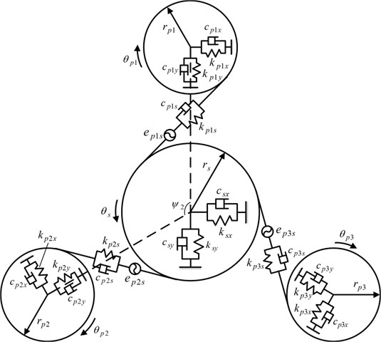
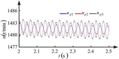
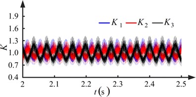
Observing Figs. 7(a) and 8(a), it is apparent that the degree of fluctuation in the speed and the difference in rotational speed increases when the pinions have run-out errors. Another observation from Fig. 8(a) is that the wave periods of the rotational speeds , , and are equal to the rotational periods of pinion-1, pinion-2, and pinion-3, respectively. From Figs. 7(b) and 8(b), it is apparent that a low frequency fluctuation emerges and the degree of fluctuation increases when the pinions have run-out errors. In Fig. 8(b), the wave periods of the low frequency component of the load sharing coefficients , , and are equal to the rotational periods of pinion-1, pinion-2, and pinion-3, respectively. The maximum value of the load sharing coefficients increases from 1.2175 to 1.6125, as seen by comparing Figs. 7(b) and 8(b). The run-out errors of the pinions make the load sharing behavior of the torque coupling gear set worse.
Fig. 7Results when pinions with no run-out errors (kp= 1, ki= 1.5)
a) Rotational speed of pinions
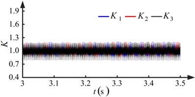
b) Load sharing coefficients of torque coupling gear set
Fig. 8Results when pinions with run-out errors (kp=1, ki=1.5)
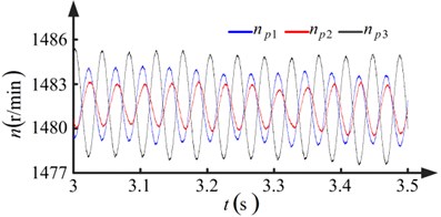
a) Rotational speed of pinions
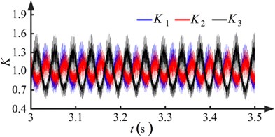
b) Load sharing coefficients of torque coupling gear set
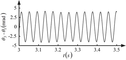
The period of the run-out error is the rotational period of the pinion. It results in the wave period of the speed of the pinion is equal to the rotational period of the pinion when there are run-out errors. This is also the case for the wave period of the low frequency component of the load sharing coefficient. The difference in rotational speed among the pinions emerges when there are run-out errors, resulting in different angular displacements for the pinions. The angular displacement difference between pinion-1 and pinion-3 is shown in Fig. 9. The pinion and gear are still in contact yet the contact statuses of the paths are different when the angular displacements are different since the tooth face is assumed to be elastic. As a result, the load sharing behavior of the torque coupling gear set is meager.
Fig. 9Angular displacement difference between pinion-1 and pinion-3
3.3. Influence of control characteristics of DTC motor on load sharing behavior of torque coupling gear set
The difference in rotational speed among the pinions that is caused by the run-out errors worsens the load sharing behavior. The difference in rotational speed can be decreased by restraining the degree of fluctuation in the rotational speed. The fluctuation in rotational speed causes the rotational speed error. An effect of the speed controller in the DTC unit is to eliminate the rotational speed error, and therefore, the fluctuation in rotational speed may be restrained. The ability to decrease the difference in rotational speed and load sharing behavior of the torque coupling gear set may be influenced by the characteristics of the speed controller under steady operating conditions.
The five pairs of proportional and integral gains shown in Table 3 are used in the speed controller. Results for conditions I and III are shown in Figs. 8 and 10, respectively. Fluctuation in the rotational speed of the pinions and the load sharing coefficients of the torque coupling gear set can be observed owing to run-out errors. It can be concluded from Figs. 8(a) and 10(a) that the degree of fluctuation in the rotational speed decreases as the proportional and integral gains increase. In Figs. 8(b) and 10(b), it is shown that the degree of fluctuation in the load sharing coefficients decreases when the proportional and integral gains increase. The maximum value of the load sharing coefficients decreases from 1.6125 to 1.4212, showing an improvement in the load sharing behavior of the torque coupling gear set.
The maxima of the load sharing coefficients under the five conditions are shown in Table 4. The maxima decrease when the proportional and integral gains increase.
Fig. 10Results when pinions with run-out errors (kp=5, ki=10)
a) Rotational speed of pinions
b) Load sharing coefficients of torque coupling gear set
Table 3Parameters of the speed controller
Condition | ||
I | 1 | 1.5 |
II | 3 | 5 |
III | 5 | 10 |
IV | 6.5 | 14 |
V | 9 | 20 |
Table 4Maxima of load sharing coefficients
Condition | max [] |
I | 1.6125 |
II | 1.4975 |
III | 1.4212 |
IV | 1.3914 |
V | 1.3386 |
The speed controller restrains the rotational speed error by changing the electromagnetic torque reference. Assume that the rotational speed error increases from to between adjacent time points. According to Eq. (1), the amplitude of variation of the electromagnetic torque reference increases when the proportional and integral gains increase. The ability to restrain the fluctuation in rotational speed is thus improved. As a result, the difference in rotational speed among the pinions decreases when the proportional and integral gains increase, therefore the load sharing behavior of the torque coupling gear set is ameliorated.
The ratio of the amplitude of variation of the electromagnetic torque to the rotational speed error is large when the speed controller has large proportional and integral gains. It corresponds to the stiff mechanical characteristic of induction motors. This stiff mechanical characteristic can improve the load sharing behavior of the torque coupling gear set. On the contrary, the ratio is small when the proportional and integral gains are small, corresponding to the soft mechanical characteristic of induction motors. This soft mechanical characteristic will aggravate the load sharing behavior of the torque coupling gear set. In conclusion, induction motors with the stiff mechanical characteristic can improve the load sharing behavior of the torque coupling gear set under steady operating conditions.
4. Conclusions
A dynamic model of the multi-motor torque coupling system is established. The effects of the run-out errors on the powertrain are analyzed under a steady operating condition. The relationships between the control characteristics of DTC motors and the load sharing behavior of the torque coupling gear set are studied under the same operating condition.
The degree of fluctuation in the rotational speed of the pinions and the speed difference among the pinions increases when the pinions have the run-out errors. The run-out errors cause the load sharing behavior of the torque coupling gear set to deteriorate, with the maximum of the load sharing coefficient increasing from 1.2175 to 1.6125. The difference in rotational speed among the pinions results in unsynchronized contact statuses among the paths, therefore the load sharing behavior of the torque coupling gear set deteriorates.
The degree of fluctuation in the rotational speed of the pinion and the speed difference among the pinions decreases when the proportional and integral gains increase. Moreover, the degree of fluctuation and the maximum of the load sharing coefficient decrease as well. The load sharing behavior of the torque coupling gear set is improved. Induction motors with the stiff mechanical characteristic can ameliorate the load sharing behavior of the torque coupling gear set. This study lays a foundation for controlling the load sharing behavior of the torque coupling gear set.
References
-
Wei Jing, Sun Qinchao, Sun Wei, et al. Dynamic analysis and load-sharing characteristic of multiple pinion drives in tunnel boring machine. Journal of Mechanical Science and Technology, Vol. 27, Issue 5, 2013, p. 1385-1392.
-
Yu Haidong, Eberhard Peter, Zhao Yong, et al. Sharing behavior of load transmission on gear pair systems actuated by parallel arrangements of multiple pinions. Mechanism and Machine Theory, Vol. 65, 2013, p. 58-70.
-
Shaoping Bai, Stephane Caro A nonlinear motor-gear model and its application to share-loading analysis of wind turbine yawing mechanisms. Proceedings of the ECCOMAS Thematic Conference Multibody Dynamics, 2011, p. 1-10.
-
Shu Ruizhi, Liu Zhenjun, Liu Changzhao, et al. Load sharing characteristic analysis of short driving system in the long-wall shearer. Journal of Vibroengineering, Vol. 17, Issue 7, 2015, p. 3572-3585.
-
Li Xianhong, Yu Haibin, Wang Jin, et al. Dynamic modeling and analysis of shield TBM cutterhead driving system. Journal of Dynamic Systems, Measurement, and Control, Vol. 132, Issue 4, 2010, p. 1-14.
-
Li Xianhong, Yu Haibin, Yuan Mingzhe, et al. Study on the linear dynamic model of shield TBM cutterhead driving system. 37th Annual Conference on IEEE Industrial Electronics Society, 2011, p. 3864-3871.
-
Li Xianhong, Yu Haibin, Zeng Peng, et al. Dynamic two-dimensional nonlinear vibration modeling and analysis for shield TBM cutterhead driving system. Transactions of the Canadian Society for Mechanical Engineering, Vol. 38, Issue 4, 2014, p. 417-463.
-
Li Xianhong, Yu Haibin, Yuan Mingzhe, et al. Research on dynamic models and performances of shield tunnel boring machine cutterhead driving system. Advances in Mechanical Engineering, 2013, p. 1-29.
-
Zhang K.-Z., Yu H.-D., Zeng X.-X., et al. Numerical simulation of instability conditions in multiple pinion drives. Proceedings of the Institution of Mechanical Engineers, Part C: Journal of Mechanical Engineering Science, 2011, p. 1319-1327.
-
Zhang Hao, Wang Meiling, Han Qingkai, et al. Dynamic behaviors of the cutterhead driving system in tunneling boring machine with impact. Proceedings of the Institution of Mechanical Engineers, Part C: Journal of Mechanical Engineering Science, 2015, p. 1-11.
-
Kahraman Ahmet Load sharing characteristics of planetary transmissions. Mechanism and Machine Theory, Vol. 29, Issue 8, 1994, p. 1151-1165.
-
Bodas Ajit, Kahraman Ahmet Influence of carrier and gear manufacturing errors on the static load sharing behavior of planetary gear steps. JSME International Journal, Series C, Mechanical Systems, Machine Elements and Manufacturing, Vol. 47, Issue 3, 2004, p. 908-915.
-
Boguski B., Kahraman A. A new method to measure planetary load sharing and sun gear radial orbit of planetary gear sets. Journal of Mechanical Design, Vol. 134, Issue 7, 2012, p. 169-180.
-
Singh Avinash Load sharing behavior in epicyclic gears: physical explanation and generalized formulation. Mechanism and Machine Theory, Vol. 45, Issue 3, 2010, p. 511-530.
-
Singh Avinash Epicyclic load sharing map-development and validation. Mechanism and Machine Theory, Vol. 46, Issue 5, 2011, p. 632-646.
Cited by
About this article

The authors appreciate the supports by the State Key Development Program of Basic Research of China (2014CB046304).
