Abstract
In view of the problems in the use of wheel side drive system, torsion beam type electric driving axle is proposed for the solution. First, with the vehicle parameters of a certain electric vehicle as a sample, the torsion beam driving axle is matched and designed and the three-dimensional model was drawn with the help of CATIA; secondly, the stiffness and strength of the driving axle are analyzed with the help of ANSYS software under five working conditions; finally, the modal analysis of the driving axle structure is carried out. It is verified from the three aspects of stress, deformation and inherent mode that the designed driving axle can meet the limit requirements of China's national standards for vehicle driving axles, which proves the rationality and effectiveness of the design scheme.
Highlights
- A driving axle is designed and named as the torsion beam electric driving axle, which incorporated the wheel side drive system into the torsion beam car suspension.
- The torsion beam electric driving axle can completely replace the traditional non-power torsional beam rear axle.
- The driving axle housing can meet the limit requirements of Chinese national standards for vehicle driving axle from two aspects of stress and deformation.
- The torsion beam electric driving axle is suitable for all types of new energy vehicles, including hybrid electric vehicles, pure electric vehicles, fuel cell vehicles, etc.
1. Introduction
The common driving form of electric vehicle is the same as that of traditional internal combustion engine. It only changes the power source, which reduces the pollution to the environment, but the power output of motor is far less than that of internal combustion engine, and the lengthy transmission chain will waste a lot of electric energy. In order to improve the power output, the power of the motor is often increased, which makes the volume of the motor too large, occupies a lot of vehicle chassis space, increases the weight of the vehicle and affects the power comfort of the vehicle. Therefore, distributed drive vehicle came into being. Distributed drive vehicle is driven by more than two power sources, and each power source transmits the power to its corresponding driving wheel through its own driving half shaft, which will make the vehicle have obvious advantages in control, economy and power.
The driving system types of distributed drive vehicles mainly include: wheel hub motor drive, wheel side motor drive, two motors drive, etc. Because each type of driving system has two-wheel and four-wheel drive, this paper mainly takes the two rear wheel drive as a representative to explain its advantages and disadvantages. The four-wheel drive is similar.
Fig. 1 shows an electric vehicle driven by a single motor. Compared with the traditional internal combustion engine vehicle, it only replaces the internal combustion engine with the motor, and the other transmission mechanisms are basically unchanged. Fig. 2 shows an electric vehicle driven by two motors, which uses two motors to drive the front axle and rear axle of the vehicle respectively on the basis of centralized driving by a single motor.
Fig. 3 shows an electric vehicle with dual motor rear wheel drive. Wheel side drive mainly places the motor and reduction mechanism in the rim to directly drive the hub. The motor is a high-speed inner rotor motor. This driving mode mainly drives the connected wheel independently by two or more motors, so the driving force of the drive motor is relatively small. However, because the motor is arranged in the wheel and the fixed mechanisms such as driving axle and half shaft are cancelled, the motor itself will be subjected to large lateral force during driving. Without the support of the rear axle, the position accuracy of each wheel can’t be guaranteed, moreover, every driving motor can’t fail. As long as one drive motor fails, the vehicle can’t keep running normally, resulting in poor fault tolerance.
Fig. 1The electric vehicle with single motor centralized drive
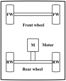
Fig. 2The electric vehicle driven by two motors
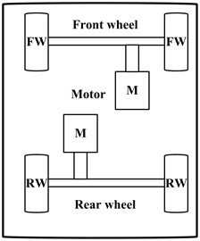
Fig. 3The electric vehicle driven by wheel side motor
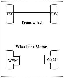
Fig. 4The electric vehicle driven by wheel-hub motor
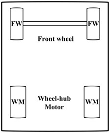
Fig. 4 shows the electric vehicle with wheel-hub motor and rear wheel drive. Hub drive is mainly to place the motor directly in the rim without speed reduction mechanism. The motor is a low-speed external rotor motor. The motor is arranged inside the wheel-hub, which has the advantages of compact structure, no occupation of vehicle chassis space, reduced overall vehicle mass and good driving stability. However, due to the high technical requirements, complex design of wheel-hub motor and high cost, it has not been popularized.
Through the analysis of the advantages and disadvantages of the above two rear wheel drive types of distributed drive vehicles, this paper focuses on the improvement of the shortcomings of the wheel side drive system. The main solution is to add a torsion beam between the driving wheels on both sides, so that it can bear the load from the body and wheels, ensure the feasibility of single motor drive and meet the requirements of long-term reliable driving.
Suspension is mainly a device for transmitting force between vehicle body and axle or wheel. It can be generally divided into independent suspension and non-independent suspension. The independent suspension is mainly that the wheels on both sides are independently connected to the vehicle body through the elastic suspension system, the runout of the left and right wheels does not interfere with each other, which can effectively reduce the vehicle body vibration. The independent suspension has the advantages of light weight, low body center of gravity and good driving stability, but its structure is complex and its cost is high. The wheels on both sides of the non-independent suspension are connected by an integral frame, which is connected with the vehicle body through elastic elements. Non-independent suspension has the advantages of low manufacturing cost, simple maintenance and strong bearing capacity, but its driving comfort and operational stability are worse than independent suspension.
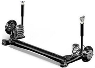
The performance and manufacturing cost of torsion beam suspension are between independent suspension and non-independent suspension, also known as semi-independent suspension. As shown in Fig. 5, this type of suspension is widely used in the rear suspension of traditional vehicles and new energy vehicles, and its main components include shock absorber, spiral spring, torsion beam, etc. [1-3]. The main function of the torsion beam is to make the vibration of one wheel not affect the other wheel through the torsion deformation of the torsion beam when one wheel has slight runout, so as to maintain the stability of the vehicle body and improve the ride comfort [4-5].
Fig. 5The torsion beam semi-independent suspension
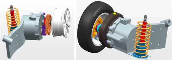
In this paper, the wheel side drive system is integrated with the torsion beam semi-independent suspension, and a driving axle is designed and named as the torsion beam electric driving axle. The torsion beam type driving axle comprises: retaining the drive motors on both sides of the wheel side drive system, and connecting the motors on both sides with a torsion beam suspension. A reducer with fixed speed ratio is added between the driving motor and the wheel to realize the function of reducing speed and increasing torque. The contributions of this paper are listed as follows:
1. In view of the limitation that the traditional wheel side drive motor is not easy to be installed in the wheel hub in the process of use, a motor is arranged on the torsion beam vehicle rear axle to turn the traditional rear axle into a driving axle. While improving transmission efficiency and saving energy, the lateral force and vibration impact on the motor itself during driving can be reduced with the help of the damping performance of the semi-independent torsion beam suspension.
2. It is proposed to add torsion beam and reducer mechanism on the basis of wheel side motor drive. The torsion beam connects the drive motors on both sides. At this time, each drive motor on the vehicle drives a single-sided wheel independently through the reducer.
3. With the support of the torsion beam rear axle, when the motor system on one side of the driving axle fails, the vehicle can still drive at a slow speed by using the clamping of the vehicle steering system, which can improve the fault tolerance of the vehicle.
4. In terms of structure, the integrated design of the driving axle can enhance the transmission of force and torque between the vehicle and the wheel.
2. Structure design
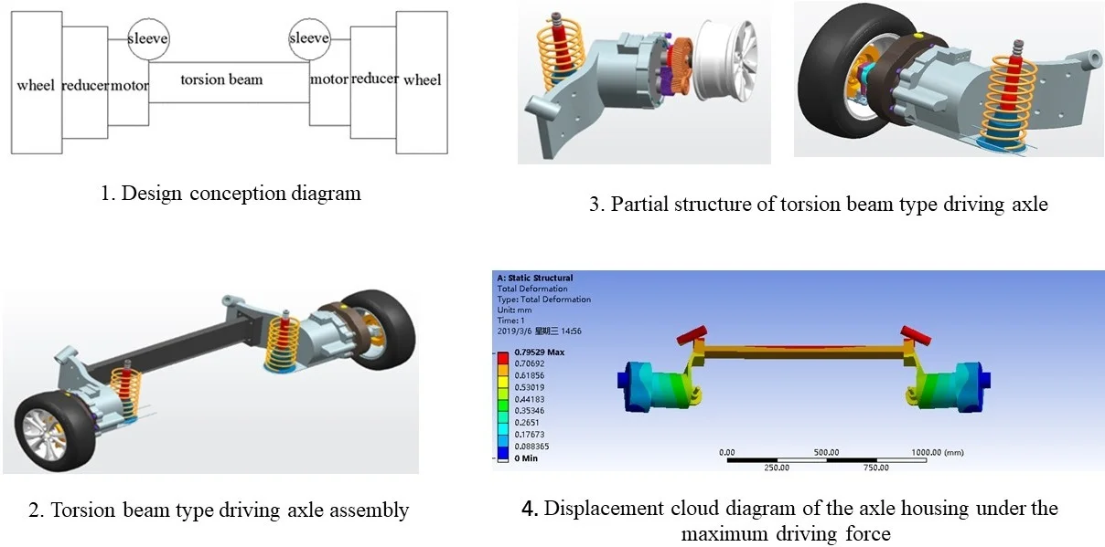
Fig. 6 shows the model diagram of the torsion beam type driving axle according to the design concept. The wheels on both sides are driven by the motor through the reducer which is mainly used to reduce the motor speed and increase the output torque. Regarding the design parameters of the torsion beam type electric driving axle: the maximum load mass is 1000 kg; the maximum torque undertaken by the transmission mechanism is 430 N∙m the maximum motor speed is 8000 r/min; the total length of the driving axle is 1500 mm, the torsion beam length is 610 mm, the transmission ratio of the two stage reducer is2, 3. Based on the design parameters, the three-dimensional geometric model of the driving axle system established by the three-dimensional software CATIA is shown in Fig. 7.
The motor shells on both sides are connected by torsion beams. A sleeve is welded to the connecting part of the motor shell and the torsion beam. The left sleeve forms angles of 135°, 45°, and 45° respectively with the -axis, -axis, and -axis, and the right and left sides are symmetrical. The entire torsion beam type driving axle is suspended on the vehicle body through sleeves on both sides to form a fixed connection. Compared with the traditional nut and screw connection, it not only saves material but also reduces the impact of the threaded hole on the rigidity and strength of the part.
Fig. 6Design conception diagram
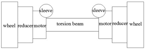
Fig. 7Torsion beam type driving axle
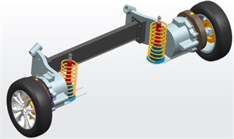
a) Torsion beam type driving axle assembly
b) Partial structure of torsion beam type driving axle
3. Analysis on stiffness and strength of torsion beam type driving axle
3.1. Establishment of finite element model
The torsion beam type driving axle consists of 5 parts: two motor shells, two reducer shells, and torsion beam. The components are connected by bolts. In the finite element analysis, each bolt connection is regarded as a rigid connection. Some chamfers and oil holes on the motor reducer shell have little influence on the modality, which is ignored. The effect of welding in some parts on the material is also not considered [6]. The connection between the motor reducer shell and the vehicle body is subject to stress at the welding point between the sleeve and the baffle. The model is meshed. The torsion beam type driving axle designed herein has big thickness, which is 8mm even at the thinnest position. Therefore, after multiple divisions, it is concluded that the optimal mesh size is 5mm.
The torsion beam type driving axle model undergoes tetrahedron meshing [7]. After the mesh generation, MERGE command is used to merge the common nodes together, and finally the finite element model of torsion beam type driving axle is obtained, as shown in Fig. 8. The mesh generation results are shown in Table 1. For material selection: When performing finite element analysis on torsion beam type driving axle, material properties should be determined, including: material name, elastic modulus, Poisson’s ratio, yield limit, and strength limit. Unlike the traditional driving axle material, the torsion beam type driving axle housing material is 45 steel. The specific parameters are shown in Table 2.
Fig. 8Finite element model of torsion beam type driving axle housing
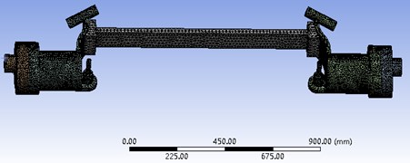
Table 1Mesh generation results
Mesh generation | Dimension mm | Division method | Mesh element | Node number |
Parameter | 5 | Tetrahedron method | 75609 | 133707 |
Table 2Driving axle material parameter table
Name | Material name | Poisson’s ratio | Elastic modulus GPa | Strength limit MPa | Yield limit MPa |
Material parameter | 45 steel | 0.3 | 210 | 600 | 355 |
3.2. Calculation of axle housing stress under the maximum vertical force
When a vehicle is driving on a rough and uneven road, it will bump up and down, and the ground will produce a vertical impact load on the driving axle [8]. In addition to the weight of the fully loaded vehicle body, the sleeve part of the motor shell connected to the vehicle body also bears the impact load of the uneven road. The dead weight of the motor and the reducer is simplified as the concentrated stress at the connection between the motor and the reducer. In addition to the gravity of the motor and the reducer, the joint is also subject to impact load.
According to the automotive driving axle design standard: the maximum load of the driving axle under the maximum vertical force is calculated as 2.5 times that of the full load stress. Different from the traditional driving axle, gravity of the motor and the reducer cannot be ignored in stress calculation of the electric driving axle [9]:
where: is the maximum vertical force experienced by the sleeve; is the weight of the fully loaded vehicle body; is impact load; is the electric vehicle mass at full load; is the acceleration of gravity; is the dynamic load coefficient. is the maximum vertical force experienced by the motor and reducer shell; is the weight of the motor reducer.
By calculation: the maximum vertical force on each side of the sleeve: 12250 N; the stress on the motor shell: 857.5 N.
3.3. Analysis on rigidity and strength of the axle housing under the maximum vertical force
Based on the finite element analysis model established above for the driving axle housing, the stress constraints of the driving axle housing under the maximum vertical force are substituted into ANSYS workbench for strength and stiffness analysis, with results shown in Fig. 9 and 10.
Fig. 9Equivalent stress cloud diagram of the axle housing under the maximum vertical force
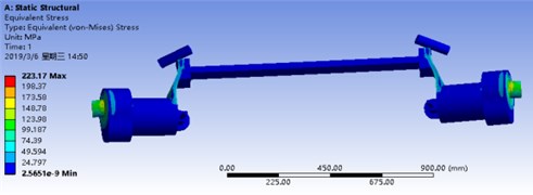
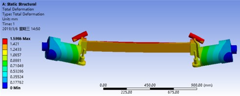
It can be seen from Figs. 9 and 10 that the maximum stress on the driving axle is 222.17 MPa, which is far less than the yield strength 355 MPa of 45 steel material; the maximum displacement change is 1.5986 mm, which falls within the limit 1.5 mm/m in driving axle deformation specified by the national standard. Therefore, the driving axle housing meets the rigidity and strength requirements.
Fig. 10Cloud diagram of the axle housing displacement under the maximum vertical force
3.4. Calculation of the axle housing force under the maximum driving force
When a fully loaded vehicle runs on the road with the maximum driving force, in addition to the weight of the fully loaded vehicle, the driving force of the driving motor that drives the rear wheels will act on the rear wheels, and the rear wheels will give the driving axle housing a shear reaction force [10]. Under this working condition:
where: is the stress on the sleeves on both sides of the torsion beam type driving axle; is the total mass of the vehicle when fully loaded; is the acceleration of gravity; is the axle load transfer coefficient. is the driving torque on one side of the driving axle; is the maximum torque of the motor; is the total transmission ratio of the reducer; is the total transmission efficiency of the drive rear axle; is gravity of the motor reducer; is the total mass of the motor reducer.
By substituting known parameters into Eqs. (3), (4), (5), there are: 5880 N, 135.5 Nm, 343 N.
3.5. Analysis on rigidity and strength of the axle housing under the maximum driving force
Based on the finite element analysis model established above for the driving axle housing, ANSYS analysis software was used to analyze the strength and stiffness of the driving axle housing under the maximum driving force. The results are shown in Fig. 11 and 12.
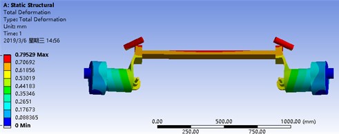
Fig. 11 shows that the maximum stress on the torsion beam type driving axle housing is 108.76 MPa; Fig. 12 shows that the maximum displacement change of the torsion beam type driving axle housing is 0.79529 mm. Therefore, the driving axle housing meets the limit requirements of national standards for rigidity and strength.
Fig. 11Equivalent stress cloud diagram of the axle housing under the maximum driving force
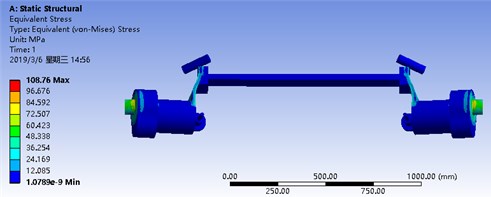
Fig. 12Displacement cloud diagram of the axle housing under the maximum driving force
3.6. Calculation of axle housing stress under the maximum braking condition
Under emergency braking conditions, the driving axle is not only subject to the vertical reaction force of the fully loaded vehicle body weight, but also the gravity of the motors on both sides plus the braking force acting on the driving axle [11].
Under this working condition, it is necessary to calculate the vertical reaction force, the maximum braking force and the maximum braking torque undertaken by the sleeves on both sides of the driving axle housing:
where: is the vertical reaction force; is the vehicle mass; is the axle load transfer coefficient. is the emergency braking force; is the braking torque; is the ground adhesion coefficient; is the wheel radius; is the gravity of the motors on both sides.
By substituting the known parameters into Eqs. (6), (7), (8), (9), there are: 3430 N, 2744 N, 822.2 Nm, 343 N.
3.7. Analysis on rigidity and strength of the axle housing under the maximum braking force
Based on the finite element analysis model established above for the driving axle housing, the ANSYS analysis software was used to analyze the strength and stiffness of the driving axle housing under the maximum braking force, as shown in Fig. 13 and 14.
Fig. 13Equivalent stress cloud diagram of the axle housing under the maximum braking force
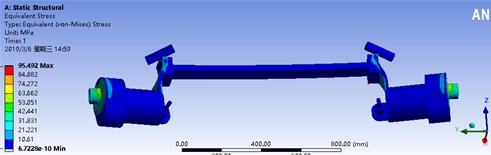
Fig. 14Cloud diagram of the axle housing displacement under the maximum braking force
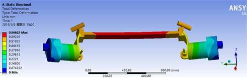
Fig. 13 shows that the maximum stress of the torsion beam type driving axle housing is 95.492 MPa; Fig. 14 shows that the maximum displacement change of the torsion beam type driving axle housing is 0.66629 mm. Therefore, the driving axle housing meets the limit requirements of national standards for rigidity and strength.
3.8. Stress calculation of the axle housing under the maximum lateral force
A fully loaded vehicle driving on the road encounters an emergency and makes a sudden turn. Then, a huge lateral force will be generated at the vehicle center of mass. When the lateral force exceeds the ground adhesion, the vehicle will slip. All gravity and lateral forces of the fully loaded vehicle will be concentrated on the slippage side of the vehicle, which will create a huge impact on the driving axle, making the driving axle directly damaged and scrapped, so it is necessary to perform load calculation and analysis under this working condition [12].
Under this working condition:
where: is the vertical force of a sleeve in the side slip direction; is the vehicle mass; is the lateral force on the side slip of the driving axle; is the ground adhesion coefficient.
By substituting the known parameters into Eqs. (10), (11), (12), there are: 9800 N, 9800 N, 343 N.
3.9. Analysis on rigidity and strength of the axle housing under the maximum lateral force
Based on the finite element analysis model established above for the driving axle housing, the ANSYS analysis software was used to analyze the strength and stiffness of the driving axle housing under the maximum lateral force. The results are shown in Fig. 15 and 16.
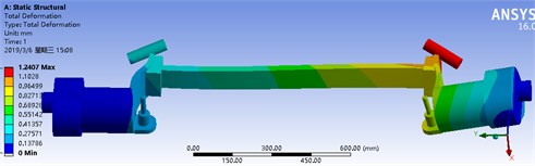
It can be seen from Fig. 15 that the maximum stress of the axle housing is 165.8 MPa; from Fig. 16, it can be seen that the maximum displacement change of the axle housing is 1.2407 mm. Therefore, the driving axle housing meets the limit requirements of national standards for rigidity and strength.
Fig. 15Equivalent stress cloud diagram under the maximum lateral force
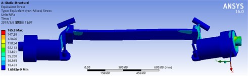
Fig. 16Displacement cloud diagram under the maximum lateral force
3.10. Stress calculation of axle housing under single motor driving conditions
If the single-side motor of the driving axle is damaged and the driving force is lost, the vehicle that matches the driving axle can still be driven by the clamping of the steering system. To this end, it is necessary to check the stress of the torsion beam type driving axle when the fully loaded vehicle is driven by a single motor. Under this working condition, in addition to the gravity of the full-loaded vehicle body on the sleeves on both sides, there are also gravity of the motors on both sides, the driving force on the right side of the vehicle and the friction on the left side of the vehicle [13]. To improve accuracy of the analysis results, the driving force here is the maximum driving force, and the friction is the sliding friction.
Under this working condition:
where: is the vertical force on the sleeves on both sides; is the total mass of the vehicle when fully loaded; is the acceleration of gravity; is the axle load transfer coefficient. is the driving torque on one side of the driving axle; is the total transmission ratio of the reducer; is the total transmission efficiency of the drive rear axle; is the maximum braking torque; is the ground adhesion coefficient; is the wheel radius.
By substituting the known parameters into Eqs. (13-16), there are: 5880 N, 135.5 Nm, 822.2 Nm, 343 N.
3.11. Analysis on rigidity and strength of axle housing under single-motor driving conditions
Based on the finite element analysis model established above for the driving axle housing, the ANSYS analysis software was used to analyze the strength and stiffness of the driving axle housing under single-motor driving conditions. The results are shown in Fig. 17 and 18.
Fig. 17Equivalent stress cloud diagram under single-motor drive conditions
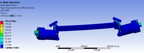
Fig. 18Equivalent displacement cloud diagram under single-motor drive conditions
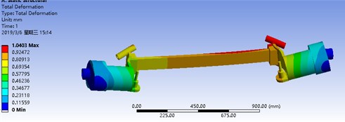
Fig. 17 shows that the maximum stress of the torsion beam type driving axle housing is 154.39 MPa; Fig. 18 shows that the maximum displacement change of the torsion beam type driving axle housing is 1.0403 mm. Therefore, the driving axle housing meets the limit requirements of national standards for rigidity and strength.
4. Modal analysis of torsion beam type driving axle housing
To improve safety of the driving axle, it is necessary to verify whether the overall natural frequency of the driving axle will resonate with the working frequency [14-15]. Therefore, modal analysis was performed on the torsion beam type driving axle, with the first six-order modal shape diagrams shown in Fig. 19 to 24.
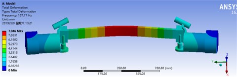
From Fig. 19 to 24, it can be concluded that the natural frequency of the first order is 95.685 Hz, that of the second order is 107.17 Hz, that of the third order is 108.68 Hz, that of the fourth order is 158.6 Hz, that of the fifth order is 164.18 Hz, and that of the sixth order is 231.6 Hz.
Fig. 19The first-order vibration mode of the axle housing
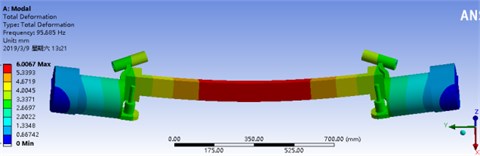
Fig. 20The second-order vibration mode of the axle housing
The modal shape results are shown in Table 3.
By synthesizing the modal shape analysis results, the first 6-order modal shape diagrams and natural frequencies, it is concluded that the axle housing mainly undergoes bending deformation during driving, and the modal frequencies of the axle housing are all above 95.685 Hz for each order, indicating that the natural frequency of the axle housing far exceeds the excitation frequency of 50 Hz on the road surface. It suggests that the external excitation from the road surface will not cause axle housing resonation, which meets the requirements of use.
Fig. 21The third-order vibration mode of the axle housing
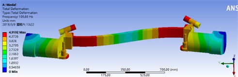
Fig. 22The fourth-order vibration mode of the axle housing
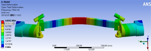
Fig. 23The fifth-order vibration The sixth-order vibration
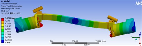
Fig. 24The sixth-order vibration mode of the axle housing
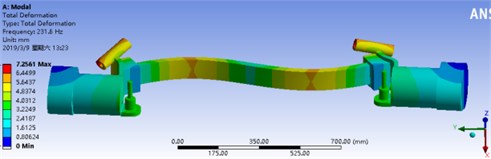
Table 3Modal shape results
Mode order | Deformation direction |
1 | Bending deformation along the direction |
2 | Bending deformation along the direction |
3 | Bending deformation around the axis |
4 | Bending deformation around the axis |
5 | Combination of axial tension and compression deformation along the axis and bending deformation along the axis |
6 | Combination of bending deformation around axis and bending deformation along axis |
5. Conclusions
Aiming at the problems that the motor of wheel side drive system is vulnerable to large lateral force during driving, and the failure of one wheel side drive motor will lead to abnormal driving and poor fault tolerance, this paper proposes a scheme based on the integration of wheel side drive system and torsion beam semi-independent suspension, designs a torsion beam electric driving axle, and carries out three-dimensional modeling and simulation verification. The specific conclusions are as follows:
1) Based on the existing non power torsional beam automobile rear axle, a torsional beam electric driving axle with power is designed, which can completely replace the traditional non power torsional beam rear axle.
2) According to the load parameters of the matched vehicle, the limit load of the torsional beam driving axle under the conditions of maximum vertical force, maximum driving force, emergency braking, lateral sliding and single motor drive is calculated, and the strength and stiffness of the driving axle housing under various limit condition are analyzed by using the finite element analysis software ANSYS. Through simulation calculation, it is verified that the driving axle housing meets the limit requirements of Chinese national standards for vehicle driving axle from two aspects of stress and deformation.
3) In order to avoid coupling resonance with the external working environment, the six-order modal analysis of the torsional beam driving axle is carried out. The simulation results show that the driving axle will not resonate with the road impact, which proves the rationality and effectiveness of the torsional beam design scheme.
The torsion beam electric driving axle is suitable for all types of new energy vehicles, including hybrid electric vehicles, pure electric vehicles, fuel cell vehicles, etc.
References
-
Shi H., Shi W. K., Liu G. Z., Zhang H. H., and Chen Z. Y., “Rigid-flexible coupling modelling and experimental study of driving axle assembly,” (in Chinese), Automotive Engineering, Vol. 41, No. 9, pp. 1073–1079, 2019, https://doi.org/10.19562/j.chinasae.qcgc.2019.09.013
-
Jiao D. F. and Liu Z. F., “NVH performance analysis and optimization of automobile driving axle,” (in Chinese), Automotive Engineering, Vol. 42, No. 2, pp. 240–249, 2020, https://doi.org/10.19562/j.chinasae.qcgc.2020.02.015
-
Fan L., Xie L. Y., and Zhang N., “Fatigue robustness and lightweight design of driving axle housing for heavy truck,” (in Chinese), Journal of Northeastern University, Vol. 40, No. 3, pp. 365–369, 2019, https://doi.org/10.12068/j.issn.1005-3026.2019.03.012
-
C. Zhou, Q. Wang, W. Ding, L. Gui, and Z. Fan, “Numerical simulation of drive axles considering the nonlinear couplings between gears and bearings,” Proceedings of the Institution of Mechanical Engineers, Part D: Journal of Automobile Engineering, Vol. 233, No. 4, pp. 851–861, Mar. 2019, https://doi.org/10.1177/0954407018755598
-
D. J. Mccrone, D. Margolis, and N. Kim, “A bond graph approach to analysis and simulation of a coupled torsion beam axle,” in 2019 Spring Simulation Conference (SpringSim), pp. 1–12, Apr. 2019, https://doi.org/10.23919/springsim.2019.8732920
-
M. Zhuqiao, R. Zheyu, G. Tongguang, Y. Zewen, H. Yijie, and F. Yeqi, “Design of fatigue endurance experiment method for automotive torsion beam based on rain-flow method,” in 2020 2nd International Conference on Artificial Intelligence and Advanced Manufacture (AIAM), pp. 428–432, Oct. 2020, https://doi.org/10.1109/aiam50918.2020.00095
-
M. Hyun, J. Yoon, J. Lee, S.-J. Heo, D. Kang, and S. Park, “Development of coupled torsion beam axle dynamic model based on beam elements,” International Journal of Precision Engineering and Manufacturing, Vol. 22, No. 1, pp. 107–121, Jan. 2021, https://doi.org/10.1007/s12541-020-00431-8
-
Y.-X. Wang, J.-T. Ni, and A.-G. Wang, “Overall strength analysis of trailing arm torsion beam suspension system,” in IOP Conference Series: Materials Science and Engineering, Vol. 422, No. 1, p. 012023, Nov. 2018, https://doi.org/10.1088/1757-899x/422/1/012023
-
Z. Liu, L. Lang, S. Ruan, M. Zhang, F. Lv, and J. Qi, “Effect of internal pressure assisted on hydroforming for CP800 high-strength steel torsion beam,” Journal of the Brazilian Society of Mechanical Sciences and Engineering, Vol. 41, No. 2, p. 800, Feb. 2019, https://doi.org/10.1007/s40430-019-1570-9
-
K. Zhang and B. Liu, “Measurement error compensation method for parameters of rear torsion beam with PSO-BP,” in 2019 International Conference on Sensing, Diagnostics, Prognostics, and Control (SDPC), p. 2019, Aug. 2019, https://doi.org/10.1109/sdpc.2019.00032
-
N. Ren, Q. Meng, and J. Mei, “Strength analysis of torsion beam of a MPV vehicle based on ADAMS,” in Journal of Physics: Conference Series, Vol. 1634, No. 1, p. 012135, Sep. 2020, https://doi.org/10.1088/1742-6596/1634/1/012135
-
F. Zhao, “Finite-element analysis on lightweight material of drive axle housing,” Revue Des Composites et des Matériaux Avancés, Vol. 31, No. 1, pp. 41–49, Feb. 2021, https://doi.org/10.18280/rcma.310106
-
S. Yang, G. Zhang, G. Niu, Y. Tuo, and Z. Ma, “Optimization design of torsion beam structure of car based on fatigue life analysis,” in Journal of Physics: Conference Series, Vol. 1601, No. 5, p. 052046, Aug. 2020, https://doi.org/10.1088/1742-6596/1601/5/052046
-
N. Zhan, X. Zhang, X. Jin, and H. Cao, “Fatigue analysis of weld region in torsion beam rear suspension system,” International Journal of Automotive Technology, Vol. 20, No. 2, pp. 247–253, Apr. 2019, https://doi.org/10.1007/s12239-019-0024-9
-
G.-X. Zhang, G.-G. Niu, and S.-S. Guo, “Analysis of fatigue life of a torsion beam based on ncode design-life,” in IOP Conference Series: Materials Science and Engineering, Vol. 423, No. 1, p. 012034, Nov. 2018, https://doi.org/10.1088/1757-899x/423/1/012034
About this article

The authors would like to thank the financial supports of the key research and development projects of Anhui (202104a05020003), the national natural science foundation of China (51575001), Anhui university scientific research platform innovation team building project (2016-2018), and Anhui development and reform commission supports R&D and innovation project ([2020]479).
