Abstract
Theoretical and simulation studies are carried out to study the propagation characteristics of Scholte waves in non-horizontal underwater interface of shallow sea. The dispersion and polarization characteristics of Scholte waves in horizontal layered underwater interface are analyzed by using wave theory and staggered grid finite difference method. The effectiveness of the method used in this paper is proved from the perspective of theory and simulation. The propagation characteristics and polarization characteristics of Scholte waves in non-horizontal underwater interface are also analyzed. At the wedge-shaped underwater interface, the particle trajectory of Scholte wave is related to the angle between the propagation direction and the underwater interface, and with the increase of the angle, the deflection angle of the particle trajectory increases. At the bulged underwater interface, the particle trajectory of seismic wave has nothing to do with the propagation direction and the bulged underwater interface, but the bulged underwater interface has a great influence on the amplitude of seismic wave. The research results are of great significance to underwater target detection and geological exploration.
1. Introduction
In order to explore a new method of underwater target detection, shallow sea seismic waves have attracted extensive attention. Scholte [1] conducted a large number of shallow sea acoustic propagation experiments after the concept of Scholte wave was proposed, and pointed out the possibility of using shallow water seismic wave to realize underwater target detection, recognition and tracking for the first time [2].Since then, scholars from various countries have carried out a large number of theoretical [3, 4], numerical [5, 6] (Finite difference method and Finite element method) and experimental [7, 8] studies on shallow sea seismic waves, and used shallow sea seismic waves in the fields of target detection, geological exploration and others. After a long and in-depth study by scholars from various countries, it is concluded that shallow sea seismic wave has the following advantages. (1) Shallow sea seismic wave is induced by low-frequency noise, and its sound source is difficult to be eliminated by noise reduction technology [9]. (2) Shallow sea seismic wave is composed of underwater sound wave, P-wave and S-wave in underwater medium, Scholte wave and various vibration waves. Using various types of waves to detect targets can improve the reliability of target detection [10]. (3) Scholte wave in shallow sea seismic wave is a surface wave propagating at underwater interface, and the amplitude of Scholte wave is large in a certain depth [11]. (4) The amplitude attenuation of Scholte wave propagating at the underwater interface is small, which can detect long-distance targets [12].
The actual shallow sea environment is relatively complex, and mountains, basins, steep slopes and sedimentary layers are distributed on the seabed, which has a great impact on sound propagation, especially shallow sea seismic waves propagating at the underwater interface. At the underwater interface, low frequency/very low frequency Scholte seismic waves have strong penetration ability. Therefore, the research on the propagation characteristics of Scholte seismic waves at the underwater interface is of great significance to underwater medium inversion, petroleum geological exploration and target detection [13, 14]. However, there are few reports on the propagation characteristics of Scholte seismic waves in complex underwater environment.
In this paper, the propagation characteristics of shallow sea seismic wave at non-horizontal underwater interface are studied, and the dispersion characteristics and propagation law of Scholte wave in complex underwater environment are analyzed. The dispersion equation and displacement equation of Scholte wave are derived by using wave theory. The simulation of shallow sea seismic wave propagation process is realized by staggered grid finite difference method. The dispersion energy diagram of shallow water seismic wave is extracted by f-k method and the particle displacement of Scholte wave is extracted by polarization method. The calculation results can determine the propagation characteristics of shallow sea seismic waves in complex marine environment, and provide a theoretical basis for underwater target detection and geological exploration.
2. Wave theory of Scholte
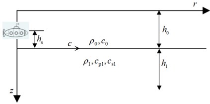
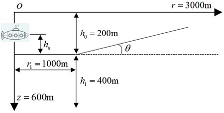
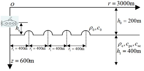
In this section, the characteristic equation of Scholte wave dispersion is derived by using the body wave equation [15] and according to the underwater interface boundary conditions. Assuming that the wave propagates along the direction, a two-dimensional shallow sea sound field model is established, as shown in Fig. 1, where, is the sound wave velocity, is the water density and is the water depth. and are the velocities of P-wave and S-wave in underwater medium respectively, ρ1 is the density of underwater medium and is the depth of underwater medium. is the distance between the sound source and the underwater interface. is the horizontal distance between the underwater interface particle and the sound source. is the Scholte wave velocity. is the depth.
Fig. 1Shallow sea sound field model
The following conditions can be obtained by using the particle displacement of water surface, sound source and underwater interface and the particularity of fluid (with compressive stress and no shear stress τ):
where, the displacement , and stress , meet the following conditions:
where, is the compression displacement vector. is the shear displacement vector. the lower corner mark 0 indicates the water medium, and the lower corner mark 1 indicates the underwater medium.
The dispersion characteristic equation of Scholte wave can be obtained by sorting out the above equations:
The ratio of Scholte wave velocity to acoustic wave velocity and shear wave velocity is different, and there will be imaginary numbers in Eq. (3), resulting in the inability or multiple solutions of the equation. Therefore, there are conditions for solving the real root of Eq. (3). The solution of different wave velocity equations has been discussed in detail in references [2] and [16], which will not be discussed too much here.
Particle displacement and particle trajectory are the key to identify Scholte waves. On the premise of determining the Scholte wave velocity, the particle displacement equation is deduced and solved. Using the boundary conditions of Eq. (1) to solve Eq. (2), the displacement equation can be sorted out.
The displacement of the horizontal and vertical components of the water medium is expressed as follows:
The displacement of the horizontal and vertical components of the underwater medium is expressed as follows:
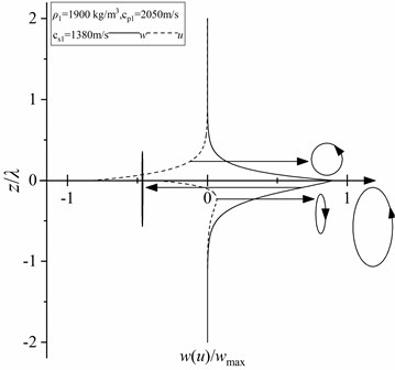
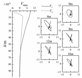
The trigonometric function sum is taken as the maximum value 1, the Eqs. (4) and (5) are solved and normalized to obtain the particle displacement curve of Scholte wave with depth. If the variation of trigonometric function sum with time is considered, the particle trajectory of Scholte wave can be obtained by solving Eqs. (4) and (5). Fig. 2 shows the change of particle displacement with depth and particle trajectory of Scholte wave. When the dominant frequency is 15 Hz, the sound wave velocity 1530 m/s and density of water 1000 kg/m3, P-wave velocity of underwater medium 2050 m/s, S-wave velocity of underwater medium 1380 m/s, density underwater medium 1900 kg/m3. It can be seen from Fig. 2 that the Scholte wave displacement is mainly concentrated at one wavelength . In underwater medium the vertical displacement of Scholte wave is always greater than the horizontal displacement. With the increase of depth, the vertical displacement of Scholte wave decreases exponentially, and the horizontal displacement of Scholte wave increases first and then decreases exponentially. At the same time, Scholte wave has polarization characteristics. At the underwater interface, the particle trajectory of Scholte wave is a counterclockwise “vertical” ellipse (the long axis of the ellipse is vertical). With the increase of depth, the particle trajectory of Scholte wave changes from counterclockwise “vertical” ellipse to “vertical” straight line, and then from “vertical” straight line to clockwise “vertical” ellipse.
Fig. 2Variation of particle displacement with depth and particle trajectory of Scholte wave
3. Results and discussion
3.1. Horizontal layered interface
The staggered grid finite difference method is used to simulate the propagation process of shallow sea seismic wave. The finite difference method uses the difference quotient to approximate the derivative to discretize the wave equation, which has the advantages of fast convergence and small memory [10]. Studies of the propagation properties of shallow sea seismic waves in complex underwater environments using finite difference methods have rarely been reported. At the same time, in order to compare the propagation characteristics of shallow sea seismic waves in complex underwater environment and ensure the accuracy and stability of the conclusions, the time and space accuracy are selected as second order. According to Fig. 1, a shallow water sound field model is established with a size of 3000 m×600 m. The thickness of the water layer is 200 m, the thickness of the underwater medium layer is 400 m, the sound wave velocity of water is 1530 m/s, and the density of water is 1000 kg/m3.Sandstone is selected as the underwater medium whose P-wave velocity is 2400 m/s, S-wave velocity is 1300 m/s, and the density is 2350 kg/m3. In the numerical calculation, the spatial step is 1 m, the time step is 0.05 ms, and the sampling time length is 3.0 s. The horizontal position of the sound source is 0 m, the height of the sound source from the underwater interface is 20 m, and the main frequency of the sound source is 30 Hz. The numerical results are shown in Fig. 3.
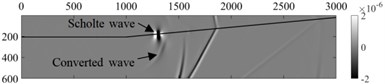
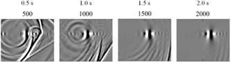
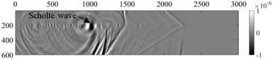
Fig. 3Wave field snapshot of horizontal interface
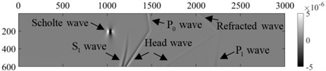
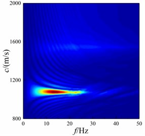
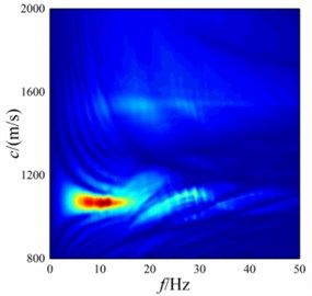
As can be seen from Fig. 3, the vibration of the underwater target (sound source) in the water forms the underwater sound wave. The sound wave contacts with the underwater medium and converts into P-wave and S-wave in the underwater medium. At the underwater interface, Scholte wave is formed by the interaction of sound wave, underwater medium P-wave and S-wave, and refracted wave and head wave are formed at the same time [10]. The amplitude of shallow sea seismic wave formed by sound sources at different heights is different. In order to extract the wave velocity of Scholte wave, the dispersion energy of shallow sea seismic wave at underwater interface is extracted by - transform [17]. In the extraction process, the vertical amplitude is selected to extract between 0-3000 m of the underwater interface with a sampling spacing of 5 m to obtain the dispersion energy of shallow sea seismic wave, as shown in Fig. 4 (the vertical amplitude is large, and in this paper only the dispersion energy of the vertical amplitude of shallow sea seismic wave is given).It can be seen from Fig. 4 that Scholte wave is the main seismic wave energy in shallow sea at underwater interface, and the height of sound source affects the wave velocity of Scholte wave, and the amplitude of Scholte wave is 5-30 Hz. Most of the shallow sea seismic wave signals extracted by mines are vibration velocity signals. In order to identify various waves in shallow sea seismic waves, it is necessary to analyze the vibration velocity of underwater interface particles. At 1500 m and 2500 m of the underwater interface, the particle vibration velocities of shallow sea seismic waves in horizontal and vertical directions at different heights of the sound source are extracted, and the particle vibration velocity in different time domain is polarized to obtain particle trajectory, as shown in Fig. 5.
Fig. 4Dispersion energy of shallow sea seismic wave
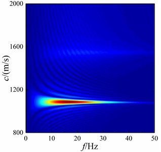
Fig. 5Vibration velocity and trajectory of particle
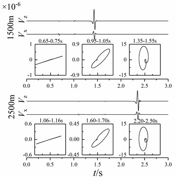
It can be seen from Fig. 4 and 5 that the particle velocity amplitude of underwater interface shallow sea seismic wave is mainly sound wave, P-wave and Scholte wave. Although the P-wave is affected by head wave and refracted wave, they have little impact on the P-wave. Therefore, the particle trajectory of underwater interface P-wave generally moves along the horizontal direction and has a small included angle with the horizontal direction. The underwater interface sound wave is mainly affected by the head wave and less by the longitudinal wave. Therefore, the acoustic wave moves in an ellipse with a certain inclination. The trajectory of Scholte wave is a counterclockwise “vertical” ellipse, and the amplitude ratio between horizontal and vertical directions is about 0.40-0.47. With the increase of distance, the attenuation of particle velocity amplitude of Scholte wave is significantly less than that of other waves.
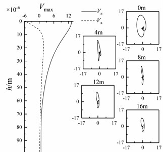
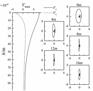
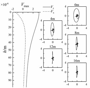
In this paper, the variation of Scholte wave amplitude along the depth direction is analyzed. When the sound source is at different heights, the horizontal and vertical amplitudes of Scholte waves with an underwater interface of 2000 m and a depth of 0-99 m are extracted. At the same time, the particle vibration velocities of Scholte waves with depths of 0 m, 4 m, 8 m, 12 m and 16 m are polarized to obtain their particle trajectories, as shown in Fig. 6.
Fig. 6Variation of Scholte wave amplitude with depth and particle trajectory of Scholte wave at different depths
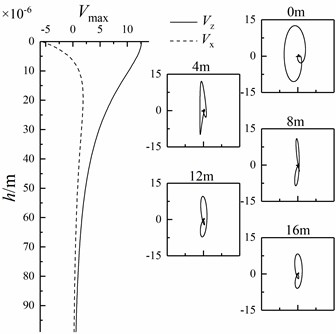
As can be seen from Fig. 6, along the depth direction, the amplitude in the vertical direction of Scholte wave decays exponentially, and the direction of amplitude does not change. The horizontal amplitude of Scholte wave changes from negative to 0, increases from 0 to a certain value, and then decays exponentially. Finally, the horizontal and vertical amplitude ratio of Scholte wave is about 0.35-0.41. The amplitude of Scholte wave in the vertical direction is always greater than that in the horizontal direction, and the amplitude of Scholte wave is mainly concentrated in one wavelength. At the underwater interface, the particle trajectory of Scholte wave is a counterclockwise “vertical” ellipse (the long axis of the ellipse is vertical). With the increase of depth, the particle trajectory of Scholte wave changes from counterclockwise “vertical” ellipse to “vertical” straight line, and then from “vertical” straight line to clockwise “vertical” ellipse. The above numerical results are consistent with the theoretical analysis results.
3.2. Wedge-shaped underwater interface
In the shallow sea environment, the underwater interface often exists with a certain slope, and the propagation characteristics of shallow sea seismic waves changes accordingly. The current research mainly uses the acoustic vector field calculation method of elastic parabolic equation to calculate the acoustic vector field in the wedge-shaped underwater interface and the distribution of seabed seismic wave [18]. In this section, the wedge-shaped underwater interface is simulated to analyze the influence of wedge-shaped underwater interface angle on shallow sea seismic wave propagation characteristics. The size of the shallow water sound field model established in this paper is 3000 m×600 m, the thickness of water medium is 200 m, the thickness of underwater medium is 400 m, and the underwater medium is sandstone. A wedge-shaped underwater interface is set at the horizontal distance 1000 m from the sound source. The angle of wedge-shaped underwater interface is less than 45°, which are 5°, 15°, 25° and 35° respectively. In the numerical calculation, the spatial step is 1 m, the time step is 0.05 ms, and the sampling time length is 3.0 s. The horizontal position of the sound source is 0 m, the height of the sound source from the underwater interface is 20 m, and the main frequency of the sound source is 30 Hz. The shallow sea sound field model of wedge-shaped underwater interface is shown in Fig. 7.
Fig. 7Shallow sea sound field model of wedge-shaped underwater interface
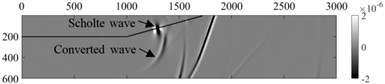
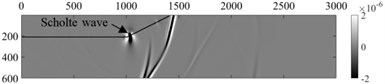
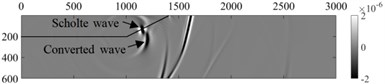
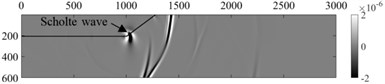
The vertical wave field snapshot of shallow sea seismic wave propagating at wedge-shaped underwater interface at different angles is shown in Figs. 8-11.
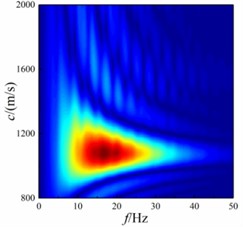
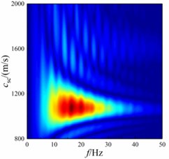
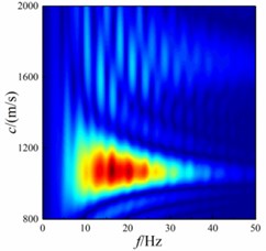
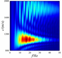
As can be seen from Fig. 8-11, Scholte wave propagates along the wedge-shaped underwater interface. Meanwhile, Scholte wave forms a converted wave after contacting with the wedge-shaped underwater interface. The energy of shallow sea seismic wave is different at different wedge-shaped underwater interface angles. In order to compare the changes of Scholte wave velocity, the dispersion energy of shallow sea seismic waves at wedge-shaped underwater interface with different angles is extracted by - transformation. In the extraction process, the vertical amplitude is selected to extract between 1000-1300 m of the underwater interface with a sampling spacing of 5 m to obtain the dispersion energy of shallow sea seismic wave, as shown in Fig. 12.
It can be seen from Fig. 12 that Scholte wave is the main shallow sea seismic wave energy at underwater interface. The wedge-shaped underwater interface affects the wave velocity and amplitude frequency concentration range of Scholte wave. With the increase of wedge-shaped underwater interface angle, the concentration range of Scholte wave amplitude decreases in terms of wave velocity, but the main concentration range of Scholte wave amplitude does not change. In terms of frequency, the amplitude frequency concentration range of Scholte wave decreases.
Fig. 8Snapshot of wave field at different sampling times, when the angle of wedge-shaped underwater interface is 5°
a) 1.25 s
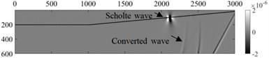
b) 2.0 s
Fig. 9Snapshot of wave field at different sampling times, when the angle of wedge-shaped underwater interface is 15°
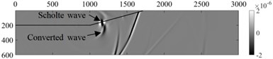
a) 1.125 s
b) 1.25 s
Fig. 10Snapshot of wave field at different sampling times, when the angle of wedge-shaped underwater interface is 25°
a) 1.0 s
b) 1.125 s
Fig. 11Snapshot of wave field at different sampling times, when the angle of wedge-shaped underwater interface is 35°
a) 1.0 s

b) 1.125 s
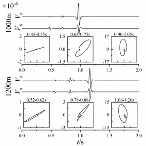
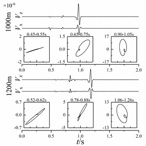
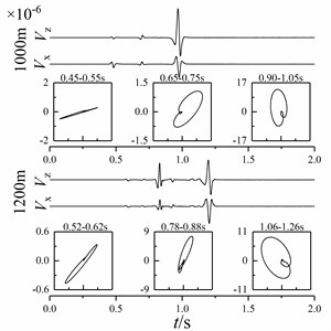
At 1000 m and 1200 m of the underwater interface, the particle vibration velocities of shallow sea seismic waves in horizontal and vertical directions of wedge-shaped underwater interface with different angles are extracted, and the particle vibration velocity in different time domain is polarized to obtain the particle trajectory, as shown in Fig. 13.
It can be seen from Fig. 13 that the amplitude of P-wave, sound wave and Scholte wave changes significantly after contacting the wedge-shaped underwater interface. Among them, the amplitude of P-wave and Scholte wave decreases and the amplitude of sound wave increases. With the increase of wedge-shaped underwater interface angle, the amplitudes of P-wave and Scholte wave attenuate and the amplitude of sound wave increases. Shallow sea seismic waves at different wedge-shaped underwater interfaces can be identified by time distance difference and polarization characteristics. Among them, the particle trajectories of P-wave, sound wave and Scholte wave have a certain angle with the horizontal direction. With the increase of wedge underwater interface angle, the angle of the particle trajectory of P-wave, sound wave and Scholte wave with the horizontal interface increases, but the particle trajectory of shallow sea seismic wave changes little.
Fig. 12f-k domain dispersion energy of shallow sea seismic wave at different wedge-shaped underwater interface angles
a)5°
b)15°
c)25°
d)35°
Fig. 13Particle vibration velocity curve and particle trajectory of shallow sea seismic wave at different wedge-shaped underwater interface angles

a)5°
b)15°
c) 25°
d)35°
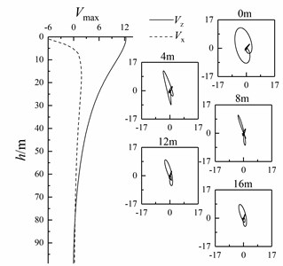
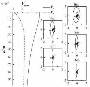
When wedge-shaped underwater interface is at different angles, the horizontal and vertical amplitudes of Scholte waves with an underwater interface of 2000 m and a depth of 0-99 m are extracted. At the same time, the particle vibration velocities of Scholte waves with depths of 0 m, 4 m, 8 m, 12 m and 16 m are polarized to obtain their particle trajectories, as shown in Fig. 14.
Fig. 14Variation of Scholte wave amplitude with depth and particle trajectory of shallow sea seismic wave at different wedge-shaped underwater interface angles
a)5°
b)15°
c)25°
d)35°
It can be seen from Fig. 14 that the particle trajectory of shallow sea seismic wave in depth direction is similar to that when there is only one layer of underwater medium (Fig. 6), but there is a certain included angle with the horizontal interface. The amplitude attenuation of Scholte wave changes obviously. With the increase of wedge underwater interface angle, the amplitude attenuation of Scholte wave is faster.
Through the above analysis, it is found that the shallow sea seismic wave forms a converted wave at the wedge-shaped underwater interface, resulting in the energy loss of shallow sea seismic wave. With the increase of wedge-shaped underwater interface angle, at the underwater interface, the amplitude frequency concentration range of Scholte wave decreases, the amplitudes of P-wave and Scholte wave decrease, and the amplitude of acoustic wave increases. Along the depth direction, the amplitude of Scholte wave decays faster. References [2] and [19] used parabolic equation and virtual source method to simulate the wedge-shaped seabed and analyze the influence of sound source on displacement field. By using the successive approximation method, reference [20] has proved the horizontal refraction effect of sound propagation under the condition of wedge-shaped underwater interface and the characteristics of interface wave propagating along the seabed interface. The results obtained by the method in this paper are basically consistent with the results of the above methods, and the propagation of shallow sea seismic waves at wedge-shaped underwater interfaces at different angles is further analyzed in this paper.
3.3. Bulged underwater interface
Underwater mountain landform often exists in the actual seabed, and the propagation characteristics of shallow sea seismic waves changes accordingly, but there are few reports in the relevant literature. In this section, the shallow sea sound field model of the bulged underwater interface is simulated, and the influence of different bulge sizes on the propagation characteristics of shallow sea seismic waves is analyzed. The size of the shallow water sound field model established in this paper is 3000 m×600 m, the thickness of water medium is 200m, the thickness of underwater medium is 400 m, and the underwater medium is sandstone. Semicircular bulges are set at the underwater interface, and the diffraction phenomenon caused by the interface wave larger than the size of the contact interface is considered [21]. After the Scholte wave in sandstone underwater medium is stabilized, the wave velocity is about 1088 m/s, the working frequency is about 1-50 Hz, and the wavelength is about 21-1088 m. The diameter of bulge is set at 20 m, 30 m, 40 m and 50 m. Four bulges are set at the underwater interface every 300m. In the numerical calculation, the spatial step is 1 m, the time step is 0.05 ms, and the sampling time length is 3.0 s. The horizontal position of the sound source is 0 m, the height of the sound source from the underwater interface is 20 m, and the main frequency of the sound source is 30 Hz. The shallow sea sound field model of bulged underwater interface is shown in Fig. 15.
Fig. 15Shallow sea sound field model of bulged underwater interface
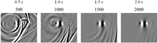
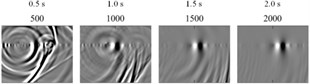
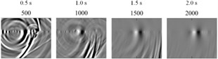
The Scholte wave field snapshots in the vertical direction of shallow sea seismic waves with different bulge diameters are extracted, and the sampling time is 1.0 s and 2.0 s, as shown in Fig. 16-19.
Fig. 16Snapshots of wave field at different sampling times when the bulge diameter dt= 20 m

a) 1.0 s
b) Snapshots of Scholte wave field at different sampling times
Fig. 17Snapshots of wave field at different sampling times when the bulge diameter dt= 30 m

a) 1.0 s
b) Snapshots of Scholte wave field at different sampling times
It can be seen from Figs. 16-19 that a large number of converted waves are formed after the shallow sea seismic wave contacts with the bulge interface. With the increase of the bulge diameter, the shallow sea seismic wave field becomes complex, including a variety of converted waves.
The energy of shallow sea seismic wave propagating at underwater interface with different bulge diameter is different. In order to compare the changes of Scholte wave velocity, the dispersion energy of shallow sea seismic waves at wedge-shaped underwater interface with different angles is extracted by - transformation. In the extraction process, the vertical amplitude is selected to extract between 0-3000 m of the underwater interface with a sampling spacing of 5 m to obtain the dispersion energy of shallow sea seismic wave, as shown in Fig. 20.
Fig. 18Snapshots of wave field at different sampling times when the bulge diameter dt= 40 m
a) 1.0 s
b) Snapshots of Scholte wave field at different sampling times
Fig. 19Snapshots of wave field at different sampling times when the bulge diameter dt= 50 m

a) 1.0 s
b) Snapshots of Scholte wave field at different sampling times
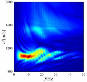
Fig. 20f-k domain dispersion energy of shallow sea seismic wave at underwater interface with different bulge diameter
a)20 m

b)30 m
c)40 m
d)50 m
It can be seen from Fig. 20 that Scholte wave is the main shallow sea seismic wave energy at underwater interface. With the increase of bulge diameter, the concentration range of Scholte wave amplitude decreases in terms of wave velocity, but the main concentration range of Scholte wave amplitude does not change. In terms of frequency, the amplitude frequency concentration range of Scholte wave decreases. In the high frequency part, the amplitude of Scholte wave diverges outward. This is because the shallow sea seismic wave with smaller wavelength cannot bypass the bulged underwater interface, and the energy of transformed wave becomes more.
Fig. 21Particle vibration velocity of shallow sea seismic wave with different bulge diameters
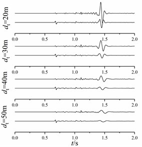
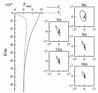
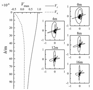
Fig. 22Variation of Scholte wave peak value with depth and particle displacement curve of shallow sea seismic wave at different depths with different bulge diameters
a)20 m
b)30 m
c)40 m
d)50 m
At 1500 m of the underwater interface, the particle vibration velocities of shallow sea seismic waves in horizontal and vertical directions at underwater interfaces with different bulge diameters are extracted, as shown in Fig. 21, and the horizontal and vertical amplitudes of Scholte wave at a depth of 0-99 m are extracted. At the same time, the particle vibration velocity of Scholte waves with depths of 0 m, 4 m, 8 m, 12 m and 16 m is polarized to obtain the particle trajectory, as shown in Fig. 22.
It can be seen from Fig. 21 and 22 that the amplitude of Scholte wave decreases after contact with the bulged underwater interface. With the increase of bulge diameter, the amplitude of Scholte wave decreases and the attenuation of Scholte wave amplitude in depth direction decreases. It is mainly because the change of Scholte wave velocity is small. With the increase of bulge diameter , the shallow sea seismic wave with small wavelength attenuates obviously, resulting in the decrease of the amplitude and frequency concentration range of Scholte wave and the increase of the overall Scholte wave length.
4. Conclusions
In this paper, the dispersion characteristic equation and displacement equation of Scholte wave are established by using wave theory, and the propagation process of shallow sea seismic wave at ideal underwater interface, wedge-shaped and bulged underwater interface is simulated by staggered grid finite method. Comparing the theoretical and simulation results, the effectiveness of the method used in this paper is proved, and the following conclusions are obtained.
1) At the underwater layered interface, Scholte wave is the main seismic wave in shallow water, and dispersion occurs. At the underwater interface, the Scholte wave moves counterclockwise. With the increase of depth, the Scholte wave changes from counterclockwise to vertical and clockwise.
2) At the wedge-shaped underwater interface, the propagation characteristics of shallow water seismic wave are basically consistent with that in the ideal underwater interface, but the particle displacement of shallow water seismic wave deflects. With the increase of wedge-shaped underwater interface angle, the deflection angle of particle displacement increases.
3) At the bulged underwater interface, the propagation characteristics of shallow sea seismic wave are basically consistent with that in the ideal underwater interface, but the amplitude attenuation of shallow sea seismic wave increases obviously. With the increase of the number of bulges, the amplitude attenuation of shallow sea seismic wave increases.
References
-
J. G. Scholte, “The range of existence of Rayleigh and Stoneley waves,” Geophysical Journal International, Vol. 5, No. 5, pp. 120–126, May 1947, https://doi.org/10.1111/j.1365-246x.1947.tb00347.x
-
H. Zhang, “Research on modeling and rule of infrasound propagation in Shallow sea,” Harbin Engineering University, 2010.
-
D. Rauch, “Experimental and Theoretical studies of seismic interface waves in coastal waters,” Bottom-Interacting Ocean Acoustics, Vol. 5, pp. 307–327, 1980, https://doi.org/10.1007/978-1-4684-9051-0_21
-
D. Rauch, “Seismic interface waves in coastal waters: A review,” Seismic interface waves in coastal waters: A review NATO, Nov. 1980.
-
L. Meng, G. Cheng, M. Zhang, and J. Shang, “Ocean sound field calculation based on high-order staggered-grid finite difference method,” Journal of naval university of engineering, Vol. 29, No. 6, pp. 55–59, 2017.
-
S. Zhao, J. Zhang, Z. Wang, H. Huang, J. Hu, and C.A. Guo, “Improving Scholte-Wave vibration signal recognition based on polarization characteristics in coastal waters,” Journal of Coastal Research, Vol. 36, No. 2, p. 382, Nov. 2019, https://doi.org/10.2112/jcoastres-d-19-00096.1
-
A. Zagrai, D. Donskoy, and A. Ekimov, “Structural vibrations of buried land mines,” The Journal of the Acoustical Society of America, Vol. 118, No. 6, pp. 3619–3628, Dec. 2005, https://doi.org/10.1121/1.2108754
-
C. B. Park et al., “Underwater MASW to evaluate stiffness of water-bottom sediments,” The Leading Edge, Vol. 24, No. 7, pp. 724–728, Jul. 2005, https://doi.org/10.1190/1.1993267
-
L. Meng, G. Cheng, Y. Chen, and M. Zhang, “On the porpogation mechanism of ship seismic wave and its application in mine fuze,” Acta Armamentarii, Vol. 38, No. 2, pp. 319–325, 2017.
-
L. Meng, X. Luo, G. Cheng, and M. Zhang, “Components and propagation characteristics of seabed seismic waves,” Journal of Shanghai Jiaotong University, Vol. 52, No. 12, pp. 1627–1633, 2018.
-
S. Kugler, T. Bohlen, T. Forbriger, S. Bussat, and G. Klein, “Scholte-wave tomography for shallow-water marine sediments,” Geophysical Journal International, Vol. 168, No. 2, pp. 551–570, Feb. 2007, https://doi.org/10.1111/j.1365-246x.2006.03233.x
-
V. S. Averbakh et al., “Application of hydroacoustic radiators for the generation of seismic waves,” Acoustical Physics, Vol. 48, No. 2, pp. 121–127, Mar. 2002, https://doi.org/10.1134/1.1460944
-
E. Muyzert, “Seabed property estimation from ambient-noise recordings: Part 2 – Scholte-wave spectral-ratio inversion,” Geophysics, Vol. 72, No. 4, pp. U47–U53, Jul. 2007, https://doi.org/10.1190/1.2719062
-
P. B. Wills and P. J. Hatchell, “Time-lapse measurements of Scholte wave velocity over a compacting oil field,” AGU Fall Meeting Abstracts, Vol. 2007, pp. S12A–2, Dec. 2007.
-
G. Z. Shao, Q. C. Li, and Z. Q. Liang, “A study on dispersion curves of guided wave in layered media with overlying liquid surface,” Chinese Journal of Geophysics, Vol. 50, No. 3, pp. 915–920, 2007.
-
X. Y. Luo, G. L. Cheng, M. M. Zhang, and Y. C. Liu, “Research on dispersion characteristics of Scholte wave in Shallow sea,” Acta Armamentarii, Vol. 39, No. 9, pp. 1786–1794, 2018.
-
J. H. Xia, High Frequency Surface Wave Method. China University of Geosciences Press.
-
H. G. Zhang, S. Yang, S. C. Piao, Q. Y. Ren, and S. Q. Ma, “A method for calculating an acoustic vector field,” Journal of Harbin Engineering University, Vol. 31, No. 4, pp. 470–475, 2010.
-
J. Tang, “Modelling of sound propagation in wedge-like oceans with elastic bottom and analyzing of horizontal refraction effects on vector fields,” Harbin Engineering University, 2019.
-
S. Yang, “Characteristics of sound propagation in sea with 3-dimensional irregular elastic bottom,” Journal of Harbin Engineering University, Vol. 41, No. 2, pp. 161–165, 2020.
-
X. Y. Guo, L. Ma, and G. Q. Wu, “A study on the propagation of interface wave in shallow sea sediments and the wave for buried objects,” Technical Acoustics, Vol. 26, No. 5, pp. 781–786, 2007.
About this article

The authors are grateful for the financial support of the Fund for Equipment Pre-research of China (No. 61406190105) and Science research funding project of Liaoning Provincial Department of Education (LJKZ0269).
