Abstract
This paper presents the vibration characteristics and its key influencing factors of a new mechanical elastic wheel (MEW). The MEW was modeled as a ring on elastic foundations (REF) with distributed spring stiffness in the radial and tangential directions. The general forced solutions of inextensible vibration were derived by the use of a modal expansion technique and Arnoldi method, and the accuracy of the solutions had been validated by FEM simulation and modal test under free suspension and various loading situations. The natural frequencies and mode shapes of the rotating MEW could be obtained under free suspension and various loading situations. Moreover, the effects of various rotational speed, loading and different number of hinges on natural frequencies were investigated. Finally, the effect of different number of hinges on the damping ratio of the MEW radial modes was also analyzed. The analysis results reflect the objective law of the actual vibration characteristics of the MEW, and provide a reference for the MEW structure optimization and the vibration characteristics of the whole vehicle.
1. Introduction
To change the existing pneumatic tire puncture damage and high speed blowout etc., developing run-flat and anti-puncture tire to guarantee high performance and security has become a consensus of the world’s major tire manufacturers. Therefore, the researchers have recently focused their attention on non-pneumatic tires with different structures. Based on that, the new mechanical elastic wheel (MEW) as a non-pneumatic safety tire structure is proposed. The MEW can be realized the basic function of traditional pneumatic tire, in additional, the problems such as stinging, puncturing and blasting damage have been avoided. Thus, the MEW is greatly satisfied with the requirements of safety performance for the special vehicles. The tire is the main component of vibration reduction, and its dynamic characteristics directly affect the driving smoothness and riding comfortableness of vehicle to a certain extent. So that the good dynamic characteristics are also one of the key factors for tire design. The structural vibration parameters of tire can also predict the interaction between tire and road excitation, suspension system and so on, and it can provide guidance for the optimization design of tire structure and suspension system.
The free and forced vibration of stationary or rotating rings has been widely studied for various ring models and for various boundary conditions. I. F. Kozhevnikov [1-2] investigated the vibration of a tyre using the model of a wheel with a reinforced tyre under various loading and various rotating situations. The non-linear vibration of a rotating ring was investigated by W. B. Bickford [3] and W. Kim [4]. S. C. Huang [5-6] derived the general equations of motion that governed both transverse and circumferential motions of rotating rings and expanded the solution to forced response. S. J. Kim [7] and Y. T. Wei [8] investigated the forced response for rotating tires under various loading using the REF model. C. R. Dohrmann [9] and S. C. Huang [10] investigated the dynamic analysis of a tire-wheel-suspension assembly using an inextensible circular ring on a foundation connected to the wheel. Meanwhile, D.H. Guan et al. [11] and G. Q. Zhao et al. [12] studied the natural frequencies and modes of tires using numerical techniques and experimental modal analysis. However, researchers have rarely focused their attention on the vibration characteristics of non-pneumatic tire. Paul F. Joseph et al. [13-14] investigated the radial stiffness of non-pneumatic tire using the curved beam model, and analyzed the influence of flexible ring material properties and the number of spokes on the radial stiffness. Doo-Man Kim et al. [15] investigated the vibration characteristics of non-pneumatic tire under various loading and rotating situations using the finite element method.
The mechanical properties, trafficability and traction ability of MEW were systematic investigated by our research group, the results indicated that the proposed wheel had good trafficability, traction ability and small rolling resistance [16-18]. To further investigate the vibration characteristics of the MEW, the MEW is modeled as a REF-model with distributed spring stiffness and damping coefficients in the radial and tangential directions in this paper. The general forced solutions of inextensible vibration are derived by the use of a modal expansion technique and Arnoldi method under free suspension and various loading situations. And the present analytical solution is compared with the results of finite element simulation and modal test. Moreover, the effects of various rotational speed, loading and different number of hinges on natural frequencies are presented.
2. Structure of mechanical elastic wheel
MEW is mainly consisted of elastic wheel (rubber tread, elastic bead ring, clasps), hub, pins, hinges and other accessories as shown in Fig. 1.
Fig. 1Structure of MEW
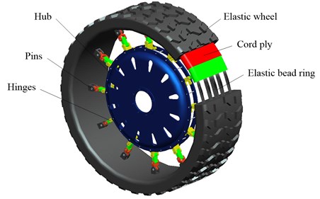
In the process of the operated MEW, the vertical loading and torque are transferred from the axle to hub, and it is transmitted to the elastic wheel through hinges. The state of hinges is changed from equilibrium to preload. The obvious flexure deformation appeared in the tangent parts between elastic wheel and the ground under the action of vertical loading. The deformed tendency of the radial shrink appears in the upper parts with respect to the free conditions, it is similar to the elliptic type. Then the generating pulling force overcomes the static friction force of the wheel in ground contact to impelling the wheel forward. Based on the design of wheel structure, the hinges only load on pulling force rather than pressure. The hub is suspended in the elastic wheel depending on the tensile strength of hinges. The hinges that closer to the ground are slightly curved, the hub slips a distance relative to the free condition downward under the action of vertical loading. The elastic wheel endures most of the excitation from the road when the wheel is moving, displays elastic deformation instantaneously, and instantaneous bending of hinges has been relieved accordingly. Meanwhile, it is shown that the transmitting type of the MEW structure has become not only high efficiency and excellent adhesion ability, but also favorable buffer damping and passing ability. Therefore, the buffer damping performance of MEW is different from the ordinary pneumatic tire [16].
3. Theoretical modeling
3.1. Model description
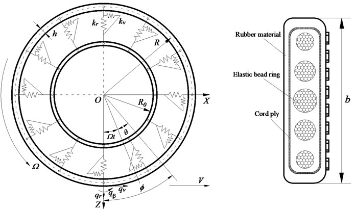
Fig. 2 shows an unconstrained ring rotating at a constant angular speed about the -axis where the -coordinate system is a space-fixed inertial frame. The MEW is modeled by a rotating ring on an elastic foundation with distributed spring stiffness and in the radial and tangential directions. The location of an element of MEW is described using the cylindrical coordinates (, ) in the non-rotating coordinate system, or (, ) in the rotating coordinate system, where is the radius of undeformed centroidal line of the ring. The ring thickness, width, applied radial force, tangential force and moment are denoted by , , , and , respectively. Only planar deformations of the ring are considered.
Fig. 2Schematic of MEW ring model and elastic wheel section structure
3.2. The equations of motion
It is assumed that the transverse shear deformation and the warping of the cross-section due to torsion negligibly small. According to the Lagrange strain theory, the flexural strain of the ring can be written as:
where and are circumferential and radial displacements of the ring, respectively, and the prime denotes the partial derivative with respect to . Note that the nonlinear term has to be included in the strains in order to compute the initial stress work correctly [8].
Inserting the expressions , , and into Eq. (1) yields:
where and represent the mid-plane displacements.
Based on the Hamilton principle, all the energies can be expressed as follows:
where , , and are potential, kinetic, and external force energy, respectively, , , and represent the initial stress, the ring section area and density.
Hamilton principle can be expressed as:
where is the vibrational symbol.
Substituting Eqs. (2)-(5) into Eq. (6), and rearranging the terms yields the final equations of motion:
where the inextensible condition, i.e., , is used. is effective modulus of the belt and the moment of inertia in Eq. (7), which means is the effective bending stiffness of the ring.
The natural frequencies of the non-rotating wheel are used to determine the model parameters and validate the model. With , , and being set to zero, Eq. (7) can be written as:
Assume the free vibration mode in the sinusoidal series as follows:
Inserting Eq. (9) into Eq. (8) yields the following natural frequency expression:
The undamped vibration frequencies of the rotating MEW can be determined by setting , and equal to zero and assuming a solution of the form:
where:
The assumed form of the solution used in the summation of Eq. (11) reflects the fact that the mode shapes for 1 are complex.
For 1, substituting Eq. (11) into Eq. (7) yields the following vibration frequency expression:
The vibration frequencies of the rotating MEW in the reference frame given by Eq. (13) are consistent with previous results in which the equations of motion are formulated in a rotating rather than a fixed reference frame.
In order to obtain the dynamic response of MEW in ground contact with a flat frictionless surface, the MEW is modeled as a ring on stiffness foundation with viscous damping coefficients and in the radial and tangential directions. The equation of motion Eq. (7) can be modified as:
As an approximation, the functions and are expanded as Fourier series:
where:
Substituting Eq. (15), (16) and into Eq. (14) yields a set of linear second-order ordinary differential equations:
where:
The assumption of a frictionless surface implies that the contact forces acting on the MEW are in the vertical direction alone. Thus, the radial and tangential forces are given by:
where is the contact force.
Consistent with the use of Eq. (15) one can verify that the ring model of the MEW only contacts the flat surface at a finite number of angular locations. Thus, the contact force can be expressed as:
where is the number of contact locations, denotes the delta function, and is the th angular location where contact occurs. The number of contact locations depends on the ring and foundation stiffness [9].
For the problems considered in this study, contact occurs at four locations. Force equilibrium in the vertical direction and contact at the angular locations imply that:
where denotes the vertical position of the ring at the angular location due to concentrated forces at the angular locations . Using the inextensibility assumption , one obtains:
And at the point of contact:
Making use of Eqs. (17, 18) and Eqs. (26)-(29) in the absence of vibration yields:
where:
Substituting Eq. (15) into Eq. (31), one obtains:
Differentiating Eq. (38) with respect to yields:
According to the Newton’s method, the solution of all cases can be obtained. The Eq. (33)-(39) and constraint Eq. (30) and (32) can be expressed solely in terms of the unknown and . The exception is for cases in which there is only one contact location and the MEW is stationary ( 0) and undamped. The solution is given simply by and .
Assume the perturbation variables , , and of the static equilibrium as follows:
Linearizing the Eq. (19) and Eq. (20) about the static equilibrium yields:
where:
Linearizing the contact boundary conditions and about the static equilibrium yields:
where:
Eq. (45), (46) and Eq. (54)-(55) can be expressed equivalently as:
where:
The mode shapes and frequencies of the system in ground contact can be determined by transforming Eq. (60) to solving the associated eigenvalue problem.
3.3. Model parameters of MEW
The geometrical and structural model parameters are obtained directly from the MEW design, as shown in Table 1.
Table 1Model geometrical and structural parameters of MEW
Parameters type | Value |
2.56×10³kg/m3 | |
0.05 m | |
0.317 m | |
0.01585 m2 | |
0.425 m |
Through analyzing the finite element simulation and experimental mode shape corresponding to each natural frequency, the physical parameters of theoretical model, including , and are determined.
4. Modal analysis and model validation
To validate the accuracy of the analytical model of the MEW, the finite element modal analysis and experimental modal analysis of the wheel are presented, respectively. And some physical parameters of the analytical model are identified by the results of the modal comparative analysis.
4.1. Finite element modal analysis
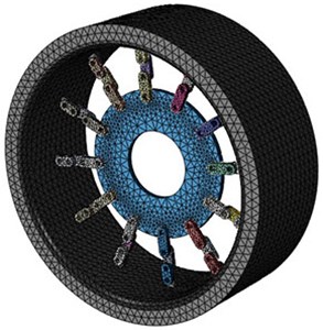
The MEW model is appropriately simplified without considering the influence of tread pattern and the irregular interface shape of hub on the calculation precision. The hinges can be simplified into 12 groups of three bar linkage. The three-dimensional geometric model of MEW is imported into ABAQUS, and the model is divided by C3D10M elements. The elastic bead ring is also modeled by solid elements, the cord ply comprises cord-rubber composite which displays the mechanics anisotropy and non-linearity, and it is modeled using the rebar layer. The generated finite element model is shown in Fig. 3. In the simulation, the stiffness calculations for the rebar elements use the same integration nodes as the calculation for the underlying rubber shell elements.
Fig. 3FEM model of the MEW
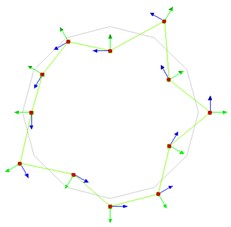
According to the results of finite element simulation, the in-plane radial modal parameters of MEW in first six order are obtained under the number of circumferential hinges is 12 sets, the simulation results are shown in Fig. 4.
4.2. Experimental modal analysis
The test wheel is a mechanical elastic wheel, it is mounted on the Suspended platform and the multifunctional testbed separately. And the test and analysis apparatus are listed in Table 2.
Table 2Apparatus for test
Apparatus | Type |
Multichannel data acquisition and processing system | SCM205 |
Modal test analysis software | LMS Test.Lab 13A |
Force hammer | 086C03 |
Acceleration sensor | 333B30 |
Computer workstation | Dell |
Modal test system for the free suspension MEW, the MEW is under the free suspension state that is shown in Fig. 5(a). According to the hammering method, the radial vibration excitation test is executed. The wheel response in the radial direction is measured with the acceleration sensor, and at some locations, the response in all three translational directions is found. Set the frequency band of 512 Hz and the frequency resolution of 0.83 Hz, and all data are logged on an LMS Test.Lab system, connects to a computer workstation. Since the natural frequency of the suspension system is very low (less than 1 Hz), and is far below the tire first natural frequency (about 30 Hz), the influence of the suspension system on modal parameters can be ignored.
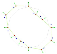
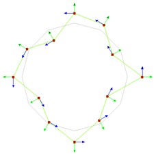
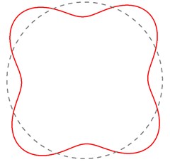
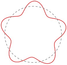
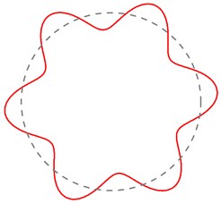
Fig. 4Simulation natural frequencies and mode shapes of the MEW
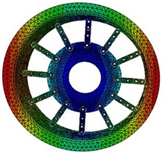
a) 30.31 Hz (1st mode)
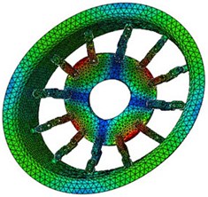
b) 90.83 Hz (2nd mode)
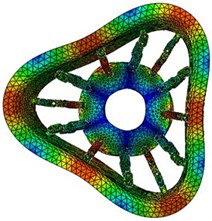
c) 107.46 Hz (3rd mode)
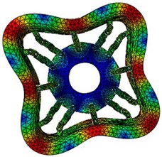
d) 134.27 Hz (4th mode)
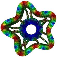
e) 158.64 Hz (5th mode)
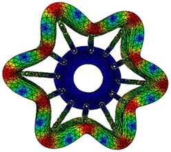
f) 207.36 Hz (6th mode)
Fig. 5Modal test of the MEW
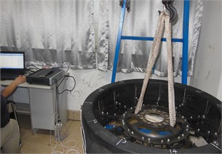
a) Suspension state
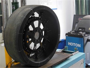
b) Loaded state
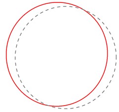
According to the parameter identification method of frequency response function matrix and PolyMAX, the vibration mode and natural frequencies of MEW are obtained under the number of circumferential hinges is 12 sets, as shown in Fig. 6.
4.3. Parameters identification and model validation
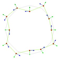
Through the contrastive analysis, the simulation modal parameters and experimental modal parameters are in good agreement. The error of mode shape is probably due to the damping of the elastic wheel and the influence of the environment. To obtain more accurate physical parameters of the analytical model, the physical parameters of Eq. (10) are fitted by the nonlinear least squares optimization method based on the natural frequencies of the wheel modal test. Combining with the natural frequencies of 1, 4, 6, then solving for the model physical parameters lead to 2.229×10⁷ N/m2, –1.898×10⁷ N/m2, and 1218.22 N·m2. Substituting the obtained physical parameters into Eq. (10) yields all natural frequencies, and which are substituted into Eq. (9) to obtain the corresponding mode shapes, the calculation results are shown in Fig. 7.
Fig. 6Experimental natural frequencies and mode shapes of the MEW
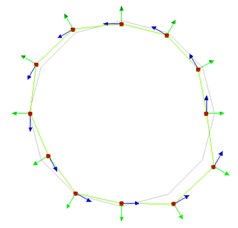
a) 32.14 Hz (1st mode)
b) 88.12 Hz (2nd mode)
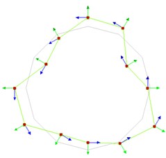
c) 105.47 Hz (3rd mode)
d) 131.73 Hz (4th mode)
e) 153.65 Hz (5th mode)
f) 202.59 Hz (6th mode)
Fig. 7Theoretical natural frequencies and mode shapes of the MEW
a) 32.26 Hz (1st mode)
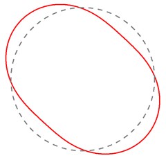
b) 94.24 Hz (2nd mode)
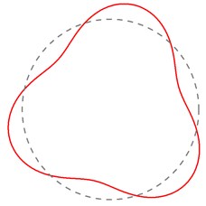
c) 112.16 Hz (3rd mode)
d) 132.05 Hz (4th mode)
e) 160.81 Hz (5th mode)
f) 203.13 Hz (6th mode)
The finite element simulation, modal test results and analytical solution are in excellent agreement for the first six order natural frequency and mode shape in Fig. 4, Fig. 6 and Fig. 7. The maximum error between finite element method results and analytical solution is 4.19 %, and the maximum error between modal test results and analytical solution is only 6.49 %. The good agreement among the predictions, simulation and experiments, to a certain extent, validates the analytical model, and it indicates that the REF model of wheel will be used as a theoretical basis to study the mechanical dynamic characteristics.
5. Influencing factors analysis
Through the vibration modal analysis of the free situations and different working conditions, it can be seen that the influence of changes of the working conditions on the mode shapes of MEW are less. Thus, according to the single variable method, the influence of different working conditions on the vibration characteristics of MEW is studied by the change of natural frequency.
5.1. Influence of loading on vibration
The vibration characteristics of MEW under different vertical loads are analyzed by the method of experimental modal and theoretical prediction. Fig. 5(b) gives the loaded state of wheel, and the vertical load during the test is real-timely monitored by means of a static strain sensor. The vibration frequencies of the MEW in ground contact under a certain load ( 3000 N) are shown in Table 3.
Table 3Natural frequencies of the loaded MEW (F= 3000 N): experimental vs. REF model
Rank | 1 | 2 | 3 | 4 | 5 | 6 |
: REF model | 35.39 | 101.13 | 119.87 | 142.08 | 171.82 | 219.86 |
: Experimental | 33.26 | 96.68 | 116.59 | 136.92 | 164.27 | 211.45 |
The theoretical prediction value and experimental results are in good agreement for the natural frequencies of the loaded MEW. According to the damping ratios of the experimental 1 and 2 modes, and making using of equations and yields the damping coefficient and .
Effect of vertical load on natural frequencies of the MEW radial vibration under the number of circumferential hinges is 12 sets as shown in Fig. 8.
The above analysis shows that the influence of changes of the vertical load on the MEW natural frequency is less. However, the modal frequency increases with the increasing of the vertical load. When the vertical load is greater, the corresponding vibration frequency is also greater when compare with the natural frequencies of the free suspension MEW. When the vertical load is larger than 4000 N, the frequency of each mode has a mutation. Because the contact area of the MEW produces a partial ‘warp’ phenomenon when the load exceeds a certain value.
Fig. 8Effect of vertical load on vibration frequency of radial mode of MEW
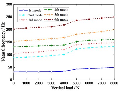
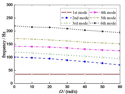
Fig. 9Effect of rotating on vibration frequency of the damped system in ground contact
5.2. Influence of rotating on vibration
The vibration modal of MEW under different rotating speed are analyzed by the finite element simulation and the linearized equations of motion Eq. (60) under a certain load, respectively. The analysis indicates that the finite element method results and analytical solution are in excellent agreement. It can be seen that the influence of rotating on the mode shapes of MEW are less, and Fig. 9 illustrates the influence of rotating on natural frequencies in the condition that the number of hinges remain unchanged.
The analysis results show the radial natural frequency decreases with the increasing of rotational speed in the damped system. The exception is for the first-order form in which the rotational speed has no effect on the first-order frequency. However, the frequencies of modes (2nd)-(6th) all have a noticeable dependence on , and the low speed has little influence on the natural frequency of MEW.
5.3. Influence of the hinges changing on vibration
According to the different matching vehicle models, the number of MEW’s hinges can be adjusted appropriately to cope with the requirements for ride comfort performance. The MEW style can be divided into 6, 9, 12 and 18 sets of hinges. Hence the influence of the number of hinges on the dynamic characteristics of the MEW is studied. Fig. 10 illustrates the influence of different number of the hinges on natural frequency of radial vibration under the free suspension state. The radial natural frequency of each mode has become increased with number of the hinges. Effect of different number of the hinges on frequencies of radial vibration under a certain load ( 5100 N) as shown in Fig. 11.
Fig. 10Effect of number of the hinges on natural frequency under the free suspension state
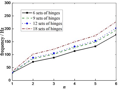
Fig. 11Effect of number of the hinges on natural frequency under a certain load
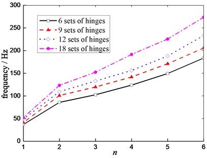
Compare with the free suspension MEW, more number of the hinges, higher the corresponding natural frequency. The natural frequency of higher mode shape is sensitive to the changing number of the hinges.
Table 4 shows the damping ratio of the MEW radial modes of free suspension under different number of hinges. The damping ratio decreases with the increasing of the number of hinges, which makes the MEW vibration amplitudes of the corresponding natural frequencies increase, especially for high frequencies. Therefore, the increase in the number of hinges helps reduce the rolling resistance of MEW, and improves the life of MEW. However, for the same vehicle model, the ride comfort performance is reduced.
Table 4Damping ratio of MEW radial modes under different number of hinges
Damping ratio (%) | Number of hinges | ||||
6 | 9 | 12 | 18 | ||
Mode order | 1 | 6.85 | 6.08 | 4.91 | 3.92 |
2 | 5.94 | 5.22 | 4.36 | 3.43 | |
3 | 5.13 | 4.37 | 3.59 | 2.71 | |
4 | 4.56 | 3.83 | 3.27 | 2.39 | |
5 | 4.24 | 3.51 | 2.82 | 2.12 | |
6 | 4.05 | 3.33 | 2.49 | 1.96 | |
6. Conclusions
1) This paper develops combined numerical analysis and test method to deal with vibration characteristics and its key influencing factors of a new mechanical elastic wheel. The MEW is modeled as a ring on elastic foundations with distributed spring stiffness in the radial and tangential directions. The vibration frequencies and mode shapes of the MEW can be analyzed by using the matrix perturbation theory and the Arnoldi method under free suspension and various loading situations. And the results of the analytical solution are validated through finite element simulation and modal test.
2) The analytical solutions are compared with the finite element simulation and the modal test under the condition of free suspension and various loading situations, it can be seen that the developed theory produces quite accurate results. With such an approach, the influence of different working conditions on vibration frequencies can be analyzed. It is shown that the modal frequency increases with the increasing of vertical loading, the corresponding vibration frequency is also greater when compare with the natural frequencies of the free suspension MEW. And the radial vibration frequency decreases with the increase of rotational speed in the damped system. Compare with the free suspension MEW, more number of the hinges, higher the corresponding natural frequency. Moreover, the damping ratio decreases with the increasing of the number of hinges, which makes the MEW vibration amplitudes of the corresponding natural frequencies increase. The analysis results reflect the objective law of the actual vibration characteristics of the MEW, and provide a reference for the MEW structure optimization and the vibration characteristics of the whole vehicle.
References
-
Kozhevnikov I. F. The vibrations of a free and loaded tyre. Journal of Applied Mathematics and Mechanics, Vol. 70, Issue 2, 2006, p. 250-256.
-
Kozhevnikov I. F. Vibrations of a rolling tyre. Journal of Sound and Vibration, Vol. 331, Issue 7, 2012, p. 1669-1685.
-
Huang S. C., Soedel W. Effects of coriolis acceleration on the free and forced in-plane vibrations of rotating rings on elastic foundation. Journal of Sound and Vibration, Vol. 115, Issue 2, 1987, p. 253-274.
-
Huang S. C., Su C. K. In-plane dynamics of tires on the road based on an experimentally verified rolling ring model. Vehicle System Dynamics, Vol. 21, Issue 1, 1992, p. 247-267.
-
Bickford W. B., Reddy E. S. On the in-plane vibrations of rotating rings. Journal of Sound and Vibration, Vol. 101, Issue 1, 1985, p. 13-22.
-
Kim W., Chung J. Free non-linear vibration of a rotating thin ring with the in-plane and out-of-plane motions. Journal of Sound and Vibration, Vol. 258, Issue 1, 2002, p. 167-178.
-
Kim S. J., Savkoor A. R. Contact problem of in-plane rolling of tires on a flat road. Vehicle System Dynamics, Vol. 27, Issue 27, 1997, p. 189-206.
-
Wei Y. T., Nasdala L., Rothert H. Analysis of forced transient response for rotating tires using REF models. Journal of Sound and Vibration, Vol. 320, Issue 1, 2009, p. 145-162.
-
Dohrmann C. R. Dynamics of a tire-wheel-suspension assembly. Journal of Sound and Vibration, Vol. 210, Issue 5, 1998, p. 627-642.
-
Huang S. C., Hsu B. S. An approach to the dynamic analysis of rotating tire-wheel-suspension units. Journal of Sound and Vibration, Vol. 156, Issue 3, 1992, p. 505-519.
-
Yam L. H., Guan D. H., Zhang A. Q. Three-dimensional mode shapes of a tire using experimental modal analysis. Experimental Mechanics, Vol. 40, Issue 4, 2000, p. 369-375.
-
Guan Yanjin, Cheng Gang, Zhao Guoqun, et al. Investigation of the vibration characteristics of radial tires using experimental and numerical techniques. Journal of Reinforced Plastics and Composites, Vol. 30, Issue 24, 2011, p. 2035-2050.
-
Gasmi Amir, Joseph Paul F., Rhyne Timothy B., et al. Closed-form solution of a shear deformable extensional ring in contact between two rigid surfaces. International Journal of Solids and Structures, Vol. 48, Issue 5, 2011, p. 843-853.
-
Gasmi Amir, Joseph Paul F., Rhyne Timothy B., et al. Development of a two-dimensional model of a compliant non-pneumatic tire. International Journal of Solids and Structures, Vol. 49, Issue 13, 2012, p. 1723-1740.
-
Lee Chihun, Ju Jaehyung, Kim Doo-Man Vibration analysis of non-pneumatic tires with hexagonal lattice spokes. Proceedings of the ASME International Design Engineering Technical Conferences and Computers and Information in Engineering Conference, Chicago, USA, 2012.
-
Wang Wei, Zhao Youqun, Wang Jian, et al. Structure analysis and ride comfort of vehicle on new mechanical elastic tire. Proceedings of the FISITA World Automotive Congress, Springer-Verlag, Berlin, Heidelberg, Vol. 10, 2013, p. 199-209.
-
Zang Liguo, Zhao Youqun, Li Bo, et al. Influence of mechanical elastic wheel configuration for traction ability. Journal of Harbin Engineering University, Vol. 35, Issue 11, 2014, p. 1-6, (in Chinese).
-
Zhao Youqun, Zang Liguo, Chen Yueqiao, et al. Non-pneumatic mechanical elastic wheel natural dynamic characteristics and influencing factors. Journal of Central South University, Vol. 22, Issue 5, 2015, p. 1707-1715.
-
Kint P., Sas P., Desmet W. Development and validation of a three-dimensional ring-based structural tyre Model. Journal of Sound and Vibration, Vol. 326, Issues 3-5, 2009, p. 852-869.
-
Kint P., Sas P., Desmet W. Measurement and analysis of rolling tire vibrations. Optics and Lasers in Engineering, Vol. 47, Issues 3-4, 2009, p. 443-453.
-
Sugiyama Hiroyuki, Suda Yoshihiro Modeling nonlinear flexible tire belt in the study of in-plane tire dynamics. Proceeding of the ASME International Design Engineering Technical Conferences and Computers and Information in Engineering Conference, Nevada, USA, 2007.
-
Kim Byoung Sam, Chi Chang Heon, Lee Tae Keun A study on radial directional natural frequency and damping ratio in a vehicle tire. Applied Acoustics, Vol. 65, Issue 5, 2007, p. 538-556.
Cited by
About this article

This research work is partially supported by the Major Exploration Project of the General Armaments Department of China (No. NHA13002), the National Natural Science Foundation of China (No. 11072106), the Fundamental Research Funds for the Central Universities (No. NP 2016412) and Funding of Jiangsu Innovation Program for Graduate Education and the Fundamental Research Funds for the Central Universities (No. KYLX_0241).
The research ideas of this paper and solution of the problem were proposed by Qiang Wang. Professor Youqun Zhao contributed to the guarantor of integrity of entire study, and gave a guide to the solution of the research problem and the writing style. Fen Lin provided some help in the writing style. Hongxun Fu helped perform the partial data processing. Xianbin Du provided some help in the process of finite element modeling.
