Abstract
The paper presents the analysis of vibrations of the crankshaft system and proposition of its modelling. At the beginning there are general information about the torsional vibration dampers. Moreover, models of different kinds of dampers are shown with their governing equations. The next section presents proposition of the algorithm of modelling of the crank-piston mechanism with a torsional vibrations damper. Furthermore, there are equations of motion of the analyzed system in this chapter. After that, the results of numerical simulations and experiments are shown. Finally, the paper is summarized by giving conclusions about the analysis of crankshaft systems with a dynamic eliminator of vibrations and their modelling.
1. Introduction
The basic features of modern drive systems is low weight and high load. The aim of weight reduction combined with the use of modern materials is to reduce production costs and to reduce emissions of harmful substances. Of course, such changes must affect the dynamics and statics of the object, which in turn should change the vibrational structure of the object. Therefore, the question is whether it is possible to shape the spectra of vibrations of the machine and how will the constructional changes of elements influence the vibrational structure of the entire engine [1-7].
In practice, a torsional vibration damper is often used to modify the vibrational structure. In piston combustion engines of the vehicles mainly rubber torsional vibration dampers are used. Experiments show that the use of eliminator of torsional vibrations influences other degrees of freedom thanks to lateral-torsional coupling. The use of this phenomenon for the needs of analysis, should facilitate the task of shaping the nature of transverse vibrations of the system. This concept seems to be especially interesting in case of crank systems of car engines, where torsional vibration dampers are very popular [8].
The reason for the creation of this work was a situation where in one of the engines of a well known manufacturer, there occurred some problems with durability of torsional vibration damper after increasing its power. Incorrect operation of this element, may generate vibrations with dangerous values which even destroy the crankshaft, therefore, the whole engine. The authors decided to make numerical model of the crankshaft of the combustion engine equipped with a torsional vibration damper. Numerical analysis should allow for an assessment of the impact of structural changes on the vibrational response of the shaft.
2. Torsional vibration dampers for piston engines
Torsional vibration dampers which are used in piston engines most often are a dynamic eliminator of vibrations [9-11]. It means that there is not any dissipation of energy. The idea of working of dynamic eliminator is based on moving away the resonance frequencies from the frequency of driving forces. Mechanism like that is an additional inert element of the system, which is connected to the system by deformable element like spring or viscous damper. In practice, the use of the dynamic eliminator of vibrations causes an increase in the number of degrees of freedom. It means that the spectral structure of the whole device has to change. Proper selection of the damper parameters allows for a change of the frequency of free vibrations in a wide range.
Most practical solutions of torsional vibration dampers can be modelled as the system of rigid bodies connected by elastic elements. These connectors usually have elastic properties, damping can be omitted in many cases. Therefore, a dynamic model illustrated below may be proposed for essential automotive and industrial applications of dampers [12]:
where: – vector of generalized coordinates of torsional vibration damper, – inertia matrix of torsional vibration damper, – operator of the right side of equation of dynamics of torsional vibration damper.
A disk elastically connected with the crankshaft is the simplest case of a torsional vibration eliminator. Fig. 1 illustrates such a system presented schematically.
Fig. 1The structural model of the torsional vibration damper. 1 – hub 2 – torsional spring, 3 – flywheel of the damper
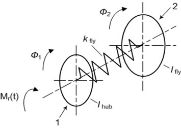
In this case (Fig. 1), the dynamic model (2) has the form of differential equations system as follows:
where: – mass moment of inertia of the hub, – mass moment of inertia of the damper flywheel, – stiffness of elastic connector (torsional spring), – the reaction moment of the crankshaft.
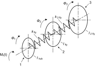
Widerange damper of torsional vibrations is a more complex mechanism. The principle of working of this device does not change. However, there is an extra degree of freedom which allows to make additional changes in the spectrum of the whole system. Such a damper is presented schematically in Fig. 2.
The following system of equations is described by a damper of this type (Fig. 2):
where: – mass moment of inertia of the second flywheel of a damper, – stiffness of the elastic connector of the second degree (torsional spring).
Fig. 2The structural model of the widerange damper of torsional vibration. 1 – hub, 2 – torsional sprint, 3 – flywheel of damper, 4 – torsional spring of second flywheel, 5 – second flywheel
3. Dynamic model of the crank system
The dynamics of a seemingly simple crank system is very complex. The main reason is a complicated geometry of the motion of the parts of the mechanism and a very complex character of deformation of the crankshaft. From the point of view of mechanics, the individual elements of this system should be treated as continuous structures with given distributions of density and stiffness tensor. In practice, such an analysis would be very difficult, even impossible. Therefore, the mechanism is most often presented as a series of stiff elements (material points or rigid bodies) connected by a weightless continuous system. It is possible to present the crank system precisely in the way presented in Fig. 3.
Fig. 3The model of the crankshaft of one piston. 1 – flywheel, 2 – crankshaft, 3 – torsional vibration damper
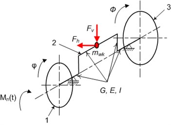
To describe the dynamics of the proposed model, it is convenient to introduce the following generalized coordinate system (Fig. 3): – rotation angle of the flywheel of the engine, – rotation angle of the disk of the torsional vibration damper, – horizontal deformation of the crank, – vertical deformation of the crank:
It can be seen that equations of motion of the analysed crank mechanism with an attached torsional vibration damper are strongly coupled nonlinear equations of the second order. Of course, there do not exist any solutions of this system in the closed form [13]. However, it is possible to find analytic approximate solution of this problem or integrate the system Eqs. (8)-(12) with numerical methods.
4. Experimental research
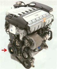
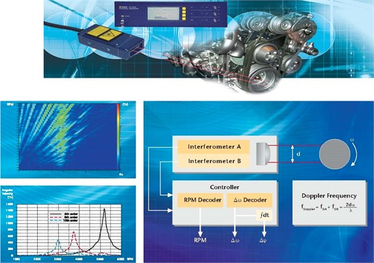
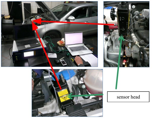
For this purpose, there was made an experiment on the car which was equipped with an engine with a spark ignition 3.6 V6 FSI fixed serially in Volkswagen Passat, Touran, Audi Q7 and Porsche Cayenne (Fig. 4). The engine was measured on a test stand [14, 15]. Thus, it was possible to be independent from the moment disruptions on the engine shaft. These disruptions resulted from irregularity of the road surface which are transferred to a drive system [16, 17].
Different types of rubber dampers of torsional vibrations of the crankshaft with different stiffness were examined. In this way, the influence of rubber hardness on the vibrating response of the shaft was defined. A laser sensor Polytec of torsional vibrations was used for measurement of the angle and velocity of torsional vibrations and instantaneous rotational speed of the crankshaft [18-21].
Fig. 4Research object with a mark of fixing place of the damper of torsional vibrations
Due to the chassis characteristics, the measurements could only take place during the vehicle acceleration in the range of engine rotational speed from about 1000 RPM to about 6000 RPM. For a few chosen rotational speeds of the engine, there were made efforts to maintain its value constant during the acceleration. The vehicle located on the chassis is shown in Fig. 22.
The following signals were recorded:
1. engine rotational speed,
2. accelerations of engine vibrations along two perpendicular axes,
3. speed of torsional vibrations of the shaft, including the hub of a torsional vibration damper and inertia ring of a torsional vibration damper.
The measurement of vertical and horizontal accelerations of engine vibrations was done with the help of vibration acceleration sensors of B&K. For the measurement of parameters connected with the movement of the crankshaft, there was used a laser system for the measurement of torsional vibration speed Polytec RLV-5500 equipped with the heads RLV-500-475. All signals were recorded by the PULSE system from B&K equipped with a measuring cassette B&K 3050 together with a software allowing for a detection and analysis of the recorded signals. The figure shows an example image of data acquisition modules placed in the collective housing type 3660 C 001 (Fig. 5). Thanks to the via LAN phase synchronization technology, full time and phase synchronization of signals was provided.
Fig. 5B&K 3660 C 001 with a set of B&K 3050 measuring modules

The RLV-5500 Rotational Laser Vibrometer benefits from digital decoding techniques, an improved S/N ratio and an expanded RPM range of up to 20,000 RPM (Fig. 6).
A compact design of the sensor head allows to get close to the measurement object. An integrated air purge system protects the optics from production of oil spray and dust. Even onboard measurement of an operating drivetrain in a moving vehicle is possible now.
The new RLV-5500 Rotational Laser Vibrometer uses a fiber optic cable to provide laser power to the small RLV-500 Sensor Head, increasing mounting and positioning options without sacrificing the precision. The RLV-5500 Controller comes with a 19’’ industrial housing and incorporates the signal processing electronics and power supply.
Fig. 6The laser system for the measurement of torsional vibrations Polytec RLV-5500
Different types of rubber dampers of torsional vibrations of the crankshaft with different stiffness were examined. In this way, the influence of rubber hardness on the vibrating response of the shaft was defined. A laser sensor Polytec of torsional vibrations was used for the measurement of the angle and speed of torsional vibrations and instantaneous rotational speed of the crankshaft [18, 22-24].
Fig. 7Research object and laser sensor of torsional vibrations Polytec
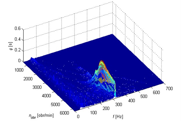
Analysis of recorded signals of vibration speed allowed to plot peak dependencies of speed amplitudes and angular displacement of vibrations of the crankshaft on time or rotational speed of the engine. It allows to determine the influence of changes used in tested torsional vibration dampers on the level and structure of torsional vibrations of the shaft. The effects of the analysis presented in Figs. 8 and 9 show how big the differences can be.
Fig. 8Dependence of velocity of the crankshaft vibrations from rotational speed for a rubber damper – rubber, hardness 60° Sh
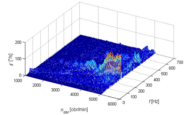
Fig. 9Dependence of the velocity of crankshaft vibrations on rotational speed for an original rubber damper.
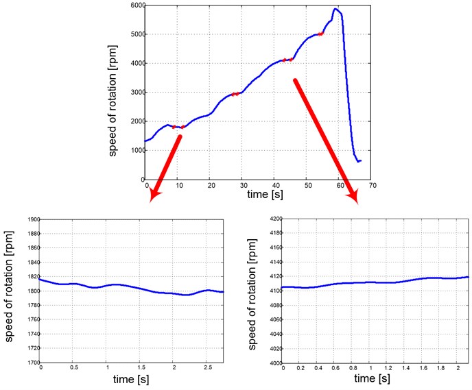
Due to the fact that for the needs of analysis carried out in this paper, the vibrational signals of the engine at constant rotational speed of the engine were necessary, from the whole measurement during the car acceleration there were chosen these fragments which could be recognized as measurements at quasi stationary rotational speed for selected parts of measurements (Fig. 10).
Fig. 10Selection of fragments of the experiment at a constant engine rotational speed
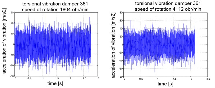
Acceleration signals of body engine vibrations for selected parts of constant rotational speed of the engine were the basis for further analysis. Example time plots are shown in Figure 7.
Fig. 11Signals of accelerations of the engine body vibrations for selected rotational speeds of the engine
5. Numerical solution and research results
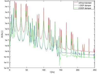
As noted above, it is possible to find a solution to the system of Eq. (8)-(12) by numerical way. Runge-Kutta 4-5 and Adams methods were used for integrating in the case of a discussed case. This decision is directly connected with high precision of both methods. The method allowing for a faster analysis with maintaining the expected precision of the results was specified. Additionally, the experimental results of the research of real combustion engine were presented. Amplitude responses of vibration accelerations obtained in experiment and by the simulation are similar (Fig. 12). The frequency structure of the proposed model is sensitive to a change of the torsional vibration damper type (Fig. 13). It can be said that a proposed model may be successfully used to describe piston engines which are used in practice e.g. to design tuned mass dampers.
Fig. 12Amplitude responses of torsional vibration accelerations – comparison of the model and the experiment
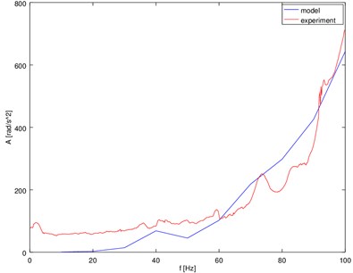
Fig. 13The spectra of torsional vibration accelerations of the model of crank system with dampers
The simulations results obtained from the proposed model are consistent with the experiments. The response of the engine changes after using additional elements of drive system such as torsional vibration dampers. It gives us possibility to design a proper damper which acts in the range of maximal amplitudes.
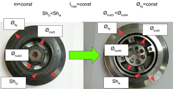
The proposed modelling procedure has a practical significance because it enables the design of modified variant of the constructional torsional vibration damper for the engine with a higher power. The modification was about the changes of the materials and reconstruction of the hub (mass change) and the appropriate selection of hardness of a rubber element (change of stiffness). The modified system was produced in DAMPOL. Both variants are shown in Fig. 14. The precise dimensions and material characteristics remain the manufacturer's mystery due to patent protection.
Fig. 14Redesigned torsional vibration damper-version before and after modification
6. Conclusions
Crank mechanism is the basis for working of most combustion engines [25]. The tendency for reduction of mass of any construction can lead to significant changes in the device dynamics. Discussed devices are very sensitive to any modifications. It is connected with a relatively low stiffness of the mechanism. That is why, detailed analysis of its dynamics is necessary. Effective use of the elastic shaft model is possible in the problem of dynamics of crank mechanism.
The simulations clearly show that the application of torsional vibration dampers allows to reduce the level of vibration system. What is more, results of numerical simulations of proposed model are checked by the experiments.
The analysis of considered system of equations indicates that there exists a strong coupling between the equations of bending and angular oscillations resulting in the energy transfer between particular degrees of freedom. That is why, there is a relation between the spectral structure of bending and torsional vibrations. It allows to assume that the basic frequencies of spectrum of a discussed object (frequencies of natural vibrations of linear part of a discussed system) will be identical without the same amplitudes. The reason for this fact is the nature of coupling appearing in the system characterized by a significant nonlinearity. It is important to emphasize that the relation between the bending and torsional vibrations cause that the vibration structures are sensitive to any changes in the technical condition of the analyzed mechanism. It means that changes of vibration structures may be a valuable source of diagnostic information [1, 8, 13].
References
-
Desbazeille M., Randall R. B., Guillet F., El Badaoui M., Hoisnard C. Model-based diagnosis of large diesel engines based on angular speed variations of the crankshaft. Mechanical Systems and Signal Processing, Vol. 24, 2010, p. 1529-1541.
-
Charles P., Sinha J. K., Gu F., Lidstone L., Ball A. D. Detecting the crankshaft torsional vibration of diesel engines for combustion related diagnosis. Journal of Sound and Vibration, Vol. 321, 2009, p. 1171-1185.
-
Burdzik R. Monitoring system of vibration propagation in vehicles and method of analysing vibration modes. Telematics in the Transport Environment, Vol. 329, 2012, p. 406-413.
-
Konieczny Ł., Burdzik R., Figlus T. The possibility to control and adjust the suspensions of vehicles. Activities of Transport Telematics, Vol. 395, 2013, p. 378-383.
-
Peruń G., Warczek J., Burdzik R., Łazarz B. Simulation and laboratory studies on the influence of selected engineering and operational parameters on gear transmission vibroactivity. Key Engineering Materials, Vol. 588, 2014, p. 266-275.
-
Szczurowski K., Radkowski S., Walczak D., Trojgo M., Zieliński Ł. Applying methods of acquisition of information from vehicle electronic components to improve work parameters of dual fuel engine. Diagnostyka, Vol. 16, Issue 4, 2014, p. 37-42.
-
Szczurowski K., Radkowski S., Walczak D., Zieliński Ł. The effect of addition of LPG and camelina oil esters on noise and vibration in a dual fuel CI engine. Diagnostyka, Vol. 15, Issue 4, 2014, p. 53-57.
-
Dabrowski Z., Zawisza M. Investigations of the vibroacoustic signals mechanical defects sensitivity is not recognized by the OBD system in diesel engines. Solid State Phenomena, Vol. 180, 2012, p. 194-199.
-
Grzędziela A. Modeling of propeller shaft dynamics at pulse load. Polish Maritime Researches, Vol. 15, Issue 4, 2008, p. 52-58.
-
Homik W., Pankiewicz J. Examinations of torsional vibration dampers used in reciprocating internal combustion engines. Polish Journal of Environmental Studies, Vol. 20, Issue 5A, 2011, p. 108-111.
-
Homik W. Broadband Torsional Dampers. Wydawnictwo Naukowe Instytutu Technologii Eksploatacji, PIB, Rzeszów, 2012, (in Polish).
-
Deuszkiewicz P., Pankiewicz J., Dziurdź J., Zawisza M. Modeling of powertrain system dynamic behavior with torsional vibration damper. Advanced Materials Research, Vol. 1036, 2014, p. 586-591.
-
Chiliński B. Analysis of disturbance torque influence on critical state in rotational systems. Transportation Problems, Vol. 8, Issue 4, 2013, p. 137-146.
-
Wierzbicki S. Laboratory control and measurement system of a dual-fuel compression ignition combustion engine operating in a cogeneration system. Solid State Phenomena, Vol. 210, 2014, p. 200-205.
-
Wierzbicki S., Śmieja M. Visualization of the parameters and changes of signals controlling the operation of common rail injectors. Solid State Phenomena, Vol. 210, 2014, p. 136-141.
-
Burdzik R., Konieczny Ł., Stanik Z., Folęga P., Smalcerz A., Lisiecki A. Analysis of impact of chosen parameters on the wear of camshaft. Archives of Metallurgy and Materials Vol. 59, Issue 3, 2014, p. 957-963.
-
Czech P., Wojnar G., Burdzik R., Konieczny Ł., Warczek J. Application of the discrete wavelet transform and probabilistic neural networks in IC engine fault diagnostics. Journal of Vibroengineering, Vol. 16, Issue 4, 2014, p. 1619-1639.
-
Dabrowski Z., Zawisza M. Investigations of the vibroacoustic signals mechanical defects sensitivity is not recognized by the OBD system in diesel engines. Solid State Phenomena, Vol. 180, 2012, p. 194-199.
-
Grzędziela A. Modeling of propeller shaft dynamics at pulse load. Polish Maritime Researches, Vol. 15, Issue 4, 2008, p. 52-58.
-
Homik W., Pankiewicz J. Examinations of torsional vibration dampers used in reciprocating internal combustion engines. Polish Journal of Environmental Studies, Vol. 20, Issue 5A, 2011, p. 108-111.
-
Homik W. Broadband torsional dlysis of torsional vibrations of the crankshaft and transverse vibrations of motor body. Logistyka, Vol. 6, 2014, p. 2965-2972, (in Polish).
-
Dąbrowski Z., Madej H. Masking mechanical damages in the modern control systems of combustion engines. Journal of KONES Powertrain and Transport, Vol. 13, Issue 3, 2006, p. 53-60, (in Polish).
-
Dąbrowski Z., Zawisza M. Diagnostics of mechanical defects not recognised by the ODB system in self-ignition engines. Combustion Engines – Silniki Spalinowe, Vol. 146, 2011, p. 99-103, (in Polish).
-
Klekot G. Application of vibro-acoustic energy propagation measures to monitor status of the object and as a tool in the manage of noise. ITE, Radom, 2012, (in Polish).
-
Dąbrowski Z. Machine Shafts. PWN, Warsaw, 1999, (in Polish).
About this article

This paper was financed by resources allocated for science in years 2012-2015 as the research project. Scientific work financed as part of the research project, Contract No. PBS1/B6/11/2012, financed value 3 359 400 PLN from Applied Research Programme from the funds of The National Centre for Research and Development in 2012-2015.
