Abstract
The paper presents modelling and the process of dynamic model identification of the crankshaft system. At the beginning some information about design, operation and test of crankshaft systems is shown. The next section describes the process of the crank-piston mechanism with a vibration damper modelling and the method of obtaining the motion equation. The last but one section demonstrates some aspects of the process of dynamic model identification. Moreover, tests and numerical simulation are presented. At the end, there is a summary of the whole paper. Conclusions about modelling and identification of the dynamic model of crankshaft systems are shown.
1. Introduction
The engineers face a difficult task because of current trends in design of modern internal combustion engines and increasingly stricter rules on emissions [1, 2]. It is necessary to design a drive system with a number of detailed assumptions which are often contradictory. The mass reduction of particular elements of the engine is usually the effect of all these activities. In most practical cases, it is associated with a change in the geometry or the use of modern materials in the design process [3, 4].
It is clear that all changes of elements of drive system can change the behaviour of dynamics and statics of a given object. Moreover, it is likely that there may appear a significant change in the spectrum of the whole device [5-7]. Thus, there arises a question about the changes of the spectrum of device vibrations when the constructional changes are introduced. Positive answer gives new possibilities of forming spectral structure of a given machine.
Modification of the vibrational structure, in many cases technical ones, is implemented by the use of a damper of torsional vibrations. It is widely known that such a device is a dynamic vibration eliminator [8-10]. The changes of basic frequencies of vibrations of the whole engine result directly from the principle of working of a damper. However, without a detailed analysis, it is impossible to predict how the spectrum of vibrations will look like after applying a damper of vibrations. Furthermore, in practice, the use of torsional vibration eliminator influences the remaining degrees of freedom because of lateral-torsional coupling. This problem is especially important in the case of car engine crank systems with high power where torsional vibration dampers are often used.
Selection of parameters of such a damper is relatively difficult. As previously noted, it is necessary to make a detailed analysis of a discussed engine, including a chosen technique of vibration elimination. For this purpose, it is important to use a dynamic model (the simplest in this case) of drive system. Unfortunately, due to the multitude of construction details of this type of device, it is not possible to determine all parameters of such a model directly. Of course, it is possible to make an attempt to make a very detailed modelling of the system. However, in practice it usually does not improve the quality of obtained results. In such cases, it is much more convenient to identify the model with a high degree of abstraction rather than analyse a very detailed system of dynamics equations [11, 12].
In classic simplified calculating methods, transverse vibrations of crankshafts and torsional vibrations are analysed independently. It is assumed that the first ones imply torsional vibrations as a whole, the second ones have the influence on the shaft fatigue [13]. Independent calculation of balancing masses and selection of dampers of torsional vibrations is the consequence of such an approach. However, transverse and torsional vibrations are coupled due to geometric nonlinearity of the system [14]. Thus, detailed analysis should be based on nonlinear equations which include these couplings. Such a model is proposed by the authors.
2. Dynamic model of the crank system
Despite its apparent simplicity, the crank system is a mechanism with complicated dynamics. It involves the deformability of all elements of its component, a nonlinear geometry of movement and of a very complex nature of the crankshaft load. Theoretically, the whole should be treated as a set of mutually interacting continuous systems described with distributions of density and stiffness tensor.
It turns out, however, that for the reasons mentioned earlier this solution is not feasible in practice. It is much simpler to present this mechanism as a series of stiff elements (material points or rigid bodies) connected by massless continuous system. The errors resulting from the assumed simplifications will be eliminated in the identification of a dynamic model which is discussed. The analyzed crank system may be presented in the way shown in the Fig. 1.
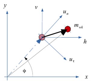
The following system of generalized coordinates is introduced to the proposed model (Fig. 1 and 2): – rotation angle of the flywheel of the engine, – rotation angle of the disc of the torsional vibration damper, – horizontal deformation of the crank, – vertical deformation of the crank.
Fig. 1The model of the crankshaft of one piston. 1 – flywheel, 2 – crankshaft, 3 – torsional vibration damper
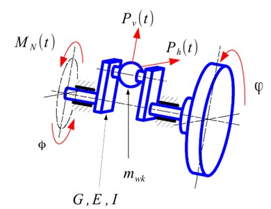
Fig. 2The crank of shaft global displacement
Due to high stiffness of crankshafts used in automotive industry, it is possible to simplify the use of small deformations of the object, and as a result, of the linear elastic model. In such a system the relation between vector of generalized forces and the displacement vector is linear. Moreover, Clapeyron systems theory shows that these relations may be presented as follows:
or more generally:
The coefficients of stiffness matrix describe the relation between particular loads and displacements of the whole system. If there is not any influence of displacement on force, the coefficient connected with this degree of freedom will be zero. Theoretical considerations show that dependencies in the considered segment of crank system Eqs. (1)-(4) will simplify. There is not an influence of each load on displacements in this structure. In this case, normal force (acting in the plane of the crank) only bends the structure and tangential load (which is perpendicular to plane of the crank) causes only transversal displacements and torsion of the system. Due to this fact, some elements of stiffness matrix will be zero for the assumed system of forces and moments:
The interaction of gas forces and piston inertia in the assumed model of crank system is shown as a system of forces affecting the crank.
The general form of the equations of motion of the crank system with a torsional vibration damper.
The previous considerations show that a seemingly simple mechanism, which is the crank system, is characterized by a very complicated mechanical structure. The main cause for this, is strongly nonlinear geometry of motion of individual elements of a discussed object. Obviously, obtaining equations of motion of this system is not simple, especially with the use of balance methods (vector methods). It is much more convenient to use formalisms of analytical mechanics, such as Lagrange or Hamilton formalism. The experience shows that in the case of mechanical systems with holonomic constraints (in the analysed problem all constraints are geometric) the Lagrange equations of second kind are very effective.
The formalism of Lagrange equations is based on the analysis of the system and total kinetic and potential energy. This is especially convenient because of the simplicity in determining mechanical quantities. Having calculated the individual parts of Lagrange formalism, the following equations of motion of the analysed crank system are obtained:
It is more convenient to use matrix notation to represent considered equations system Eqs. (6)-(10), of analyzed case. After some transformations, its matrix form is as follows:
where: – mass matrix, – stiffness matrix, – vector of generalized coordinates of crankshaft, – vector of external excitations acting on the shaft, – vector of gyroscopic forces, – vector of generalized coordinates of torsional vibration damper, – inertia matrix of torsional vibration damper, – restitutive forces vector of equation of dynamics of torsional vibration damper.
3. Torsional vibration damper modelling
Most of torsional vibration dampers in practical technical applications may be modelled as multi body system. It is a system of rigid bodies which are connected by massless deformable connectors like springs or dampers Considered system will be a dynamic eliminator of vibrations, in this case. It means that described dampers increase the number of degrees of freedom of the system. TVD is an additional inertia element connected with the crankshaft by elastic connector. The changes in number of inertial elements lead to the change of free vibration frequencies (eigenvalues) and modes of oscillations, in the case of whole system vibrations. It means that after applying a considered dynamic eliminator, the critical speeds of engine will change. Due to this fact, the vibrations of the whole power unit will be different. Moreover, it is possible that the total amplitude of vibrations decreases for some values of damper parameters. Eq. (10) describes motion of this system. It is obvious that the form of this equation depends on the type of a damper. The simplest solution is composed of disk and elastic connector, which is presented in Figs. 3 and 4.
Fig. 3Crankshaft pulley with torsional vibration damper. 1 – hub, 2 – torsional spring, 3 – flywheel of damper [17]
![Crankshaft pulley with torsional vibration damper. 1 – hub, 2 – torsional spring, 3 – flywheel of damper [17]](https://static-01.extrica.com/articles/18074/18074-img3.jpg)
Fig. 4The structural model of the torsional vibration damper. 1 – hub, 2 – torsional spring, 3 – flywheel of damper
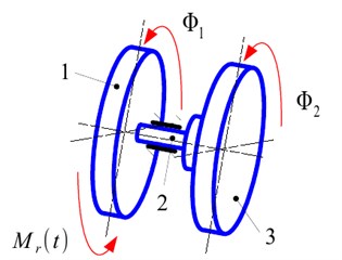
The dynamic model Eqs. (15)-(16) of presented system (Fig. 4), can be described by the following differential equations system:
where: – mass moment of inertia of the hub, – mass moment of inertia of damper flywheel, – stiffness of elastic connector (torsional spring), – the reaction moment of the crankshaft.
Fig. 5 illustrates a more complex system was It is an example of wideband torsional vibration damper which increases the number of DOF of the system by 2.
Fig. 5The structural model of the widerange damper of torsional vibration. 1 – hub, 2 – torsional spring, 3 – flywheel of damper, 4 – torsional spring of second flywheel, 5 – second flywheel
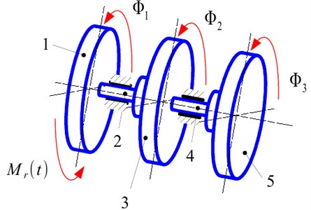
Damper of this type (Fig. 5) has the following mathematical description:
where: – mass moment of inertia of the a second flywheel of damper, – stiffness of the elastic connector of the second degree (torsional spring).
4. Modelled engine and experimental results
The examined object was Volkswagen Passat with 3.6 V6 FSI engine. It is spark ignition power unit with factory fitted torsional vibration damper. The investigated car on the chassis dynamometer with measurement system was shown in Figs. 6 and 7.
Fig. 6Examined VW Passat engine of with mounted sensors

Fig. 7Engine chamber and used sensors. 1 – three-axis accelerometer, 2 – heads of laser vibrometers
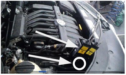
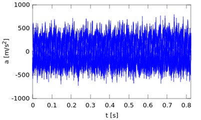
The vibrations accelerations of the head of investigated engine were measured with sampling rate which equals 32 kH. There was used Brüel & Kjær three-axis accelerometer (Fig. 7). Sensor was mounted according to piston movement direction. Sample time plot of measured accelerations of vibration was shown in Figs. 8 and 9.
Moreover, there were two Polytec laser vibrometers for future analysis. The results of these measurements were not used in the process of model identification. The test was done for accelerating and decelerating of the examined object. Based on recorded signals there was made Fourier analysis. For this purpose, the Hanning window and FFT algorithm were used.
Fig. 8Transverse vibrations accelerations of engine head for 3960 RPM
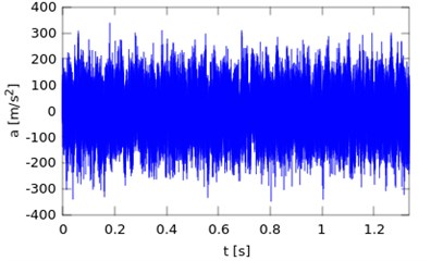
Fig. 9Transverse vibrations accelerations of engine head for 5000 RPM
5. The problem of identifying a dynamic model
The model of dynamics of the crankset may illustrate the dynamics of a real crank system [4]. It happens under the condition of precise determining its particular parameters. There does not exist the possibility of direct measurement of unknown quantities because of the simplifications used in the model. Therefore, such a model would be worthless in structural or diagnostic applications. The only effective method to enforce the compliance of theoretical and experimental results is the identification of a dynamic model [18]. The parametric identification (one in which the structure of the model is precisely determined) can be defined as follows:
where: – a model solution, – decision variables selected from the model parameters, – the selection operator in time domain (operator of time window and filtering/averaging), – permissible total error of identification process.
The decision variables should be chosen arbitrarily from the set of a model parameters. These parameters depend on each particular case of identification problem. In many cases it is convenient to choose decision variables as parameters of the system which are difficult to measure e.g. reduced stiffness or effective Young’s modulus. In this case, coefficients of crankshaft stiffness and the amplitude of extortion of gas force working in the system were chosen as decision variables.
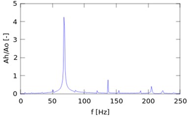
The use of selection operator in time domain is necessary because of the existence of additional information present in the measurement, which is not connected with the identified model. Selection operator can be compared to the filter but in time domain. It is very difficult to analyse signals like vibration from Figs. 8 or 9. It is connected with their complicated structure in time domain. For constant value of rotational speed of the engine the considered quantity is periodic. Due to this fact, it is more convenient to analyse measured vibrations of the engine head in frequency domain. The transformation of Eq. (21) is possible:
where: – Fourier transformation, – permissible total error of identification process in frequency domain, – measurement noise, – error of the model simplification (mismatch of the model to the real object), – the result of the experiment in frequency domain, – selection and averaging operator in frequency domain.
Dependencies Eqs. (21) and (22) make no sense without defining the relevant metrics. It is convenient to define the distance in frequency domain in the following way:
where: – a set of the main frequencies of excitation force, assuming the selection of the operator and averaging which filters the noise and irrelevant elements in the frequency range 0 250 Hz.
Function had to be introduced for the purpose of comparing the measured signals with the results of modelling.
In order to define the set of main frequencies of the excitation force it is necessary to make some preliminary analysis. Based on the results of Fourier transformation of the measured signals it is possible to select n first harmonics of angular velocity in considered frequency range. It is a demanded set of driving forces.
The displacements of vertical vibrations of the engine body measure with the first cylinder were chosen as the observed course. Assuming that the body has high stiffness, its vibrations correspond to shaft vibrations in the plane of the crank. It should be emphasized that observed vibrations can be at most linearly scaled due to the way of their propagation (transmittance between bearing and measured point). Finding this frequency response function comes down to scaling the “mechanical” part of the measurement path and is a separate task. In the works [11] and [19] it is demonstrated that this is not a necessary assumption of linearity of the transfer function. The inevitable error is compensated by finding the value of decision variables (, , , ) which are not “real” coefficients, but retain the correctness of the model. In the considered case there were five decision variables: maximum amplitude of excitation (amplitudes of each harmonics related to maximum value were taken directly from decomposition of the tangential force) and stiffness coefficients (, , , ) from . They have the following limits: 5-15, 2·103-1·105, 2·103-1·105, 2·103-1·105, 2·103-1·105.
Making a comparison of theoretical solution (Fig. 11) with the results of experiments (Fig. 12), the unknown parameters of the discussed system in the process of parametric identification are designated.
Fig. 10The registered spectrum of transverse vibration accelerations of the body of a car engine before using the selection operator
The values of decision variables in the identification process were determined with the Monte Carlo method until the compliance of the results was obtained at the assumed level. The difference between numerical computation and experiments was less than permissible total error of identification process:
assuming the compliance of basic element on the level of spectral resolution.
As the results of simulations show (Fig. 12) the proposed model is identifiable in the set of physically acceptable parameters of the system. This means that its vibrational response will be consistent (for a given level of accuracy) with experimental results.
Fig. 13Comparison of experimental and modelling results before identification process
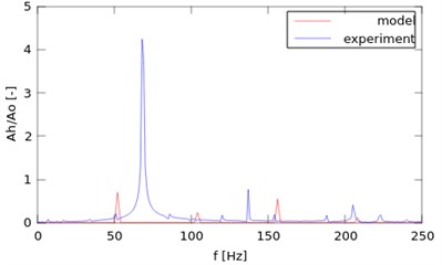
Fig. 14Comparison of experimental and modelling results after identification process
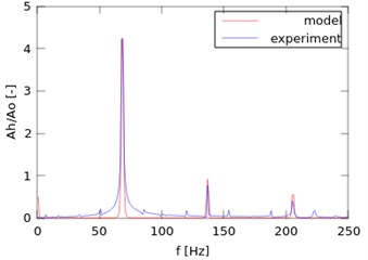
There is a comparison between unidentified and identified model in the Figs. 13 and 14. Figures show that the change of values of model parameters causes significant differences in simulation results. Due to this fact, it is necessary to make identification process of a dynamic model. Even a proper modelling procedure can give wrong results, if the parameters of the system are not correct.
The model which was previously “tuned” can be effectively used for further analysis of the dynamics of currently used engines, their design/modification and for further selection of accessories.
6. Conclusions
It is difficult to model the crank system dynamics. The main problem is connected with the “accuracy” of the model. It is possible to make a complicated model, but it will be very difficult to analyse. Simple model is easier to solve and further analysis. That is why, described approaches were shown. Of course, it is easier to identify individual elements of the system for more advanced modelling, but complex model does not guarantee that results will be consistent with experiments. For simplified models with a high level of abstraction such a process may not be directly feasible. For this reason, it is necessary to make an identification process of a dynamic model. However, the results obtained from the simple identified model will be corresponding to real object.
The paper shows the numerical solution of the proposed model and the results of experiments for the real engine. Moreover, it describes details of the "tuning" process of the considered system of equations.
Coupling of angular and lateral oscillations which is present in the model is the reason for a complicated frequency structure of the analysed object. Furthermore, it is possible to use this phenomenon in practical applications.
The proposition of model identified on the basis of experiments may serve as an important tool in the design process of systems eliminating vibrations and the measurements of engine vibrations. It can also be a valuable source of diagnostic information about the technical condition of piston engines, in particular, torsional vibration dampers [20-25]. The phenomenon of vibration coupling in the crankshaft transfers oscillations between angular and transversal displacements. It means that any change of the dynamics of torsional vibrations causes response of bending vibrations. Moreover, application of any additional elements for the purpose of torsional vibrations eliminating (e.g. TVD) will be visible in transversal dynamics. It has practical meaning because it allows for an influence on bending vibration structure of the engine by torsional oscillation. There is an additional advantage, it is possible to measure angular vibrations of the crankshaft by observing displacements of the engine body.
References
-
Szczurowski K., Radkowski S., Walczak D., Trojgo M., Zieliński Ł. Applying methods of acquisition of information from vehicle electronic components to improve work parameters of dual fuel engine. Diagnostyka, Vol. 16, Issue 4, 2014, p. 37-42.
-
Szczurowski K., Radkowski S., Walczak D., Zieliński Ł. The effect of addition of LPG and Camelina oil esters on noise and vibration in a dual fuel CI engine. Diagnostyka, Vol. 15, Issue 4, 2014, p. 53-57.
-
Grzędziela A. Modeling of propeller shaft dynamics at pulse load. Polish Maritime Researches, Vol. 15, Issue 4, 2008, p. 52-58.
-
Burdzik R., Konieczny Ł., Stanik Z., Folęga P., Smalcerz A., Lisiecki A. Analysis of impact of chosen parameters on the wear of camshaft. Archives of Metallurgy and Materials Vol. 59, Issue 3, 2014, p. 957-963.
-
Burdzik R. Monitoring system of vibration propagation in vehicles and method of analyzing vibration modes. Telematics in the Transport Environment, Vol. 329, 2012, p. 406-413.
-
Peruń G., Warczek J., Burdzik R., Łazarz B. Simulation and laboratory studies on the influence of selected engineering and operational parameters on gear transmission vibroactivity. Key Engineering Materials, Vol. 588, 2014, p. 266-275.
-
Deuszkiewicz P., Pankiewicz J., Dziurdź J. Zawisza M. Modeling of powertrain system dynamic behavior with torsional vibration damper. Advanced Materials Research, Vol. 1036, 2014, p. 586-591.
-
Homik W., Pankiewicz J. Examinations of torsional vibration dampers used in reciprocating internal combustion engines. Polish Journal of Environmental Studies, Vol. 20, Issue 5, 2011, p. 108-111.
-
Homik W. Broadband torsional dampers. Wydawnictwo Naukowe Instytutu Technologi i Eksploatacji – PIB, Rzeszów, 2012, (in Polish).
-
Dąbrowski Z., Dziurdź J. Comparative analysis of torsional vibrations of the crankshaft and transverse vibrations of motor body. Logistyka, Vol. 6, 2014, p. 2965-2972, (in Polish).
-
Batko Dąbrowski W. Z., Kiciński J. Nonlinear effects in technical diagnostics. ITE-PIB, Radom, 2008.
-
Klekot G. Application of vibro-acoustic energy propagation measures to monitor status of the object and as a tool in the manage of noise. ITE, Radom, 2012, (in Polish).
-
Dąbrowski Z. Machine Shafts. PWN, Warsaw, 1999, (in Polish).
-
Chiliński B. Analysis of disturbance torque influence on critical state in rotational systems. Transportation Problems, Vol. 8, Issue 4, 2013, p. 137-146.
-
Desbazeille M. Randall R. B., Guillet F., El Badaoui M., Hoisnard C. Model-based diagnosis of large diesel engines based on angular speed variations of the crankshaft. Mechanical Systems and Signal Processing, Vol. 24, 2010, p. 1529-1541.
-
Charles P., Sinha J. K., Gu F., Lidstone L., Ball A. D. Detecting the crankshaft torsional vibration of diesel engines for combustion related diagnosis. Journal of Sound and Vibration, Vol. 321, 2009, p. 1171-1185.
-
https://www.vibracoustic.com/sites/default/files/images/product/thumb/2118112102dkopie.jpg
-
Konieczny Ł., Burdzik R., Figlus T. The possibility to control and adjust the suspensions of vehicles. Activities of Transport Telematics, Vol. 395, 2013, p. 378-383.
-
Pakowski R. Study the Impact of the Characteristics of Flexible Couplings on the Dynamic Response of the Drive System in Terms of Time-Alignment Errors. Ph.D. Thesis, Warsaw University of Technology Printing House, 2005, (in Polish).
-
Dąbrowski Z., Zawisza M. Investigations of the vibroacoustic signals mechanical defects sensitivity is not recognized by the OBD system in diesel engines. Solid State Phenomena Vol. 180, 2012, p. 194-199.
-
Wierzbicki S. Laboratory control and measurement system of a dual-fuel compression ignition combustion engine operating in a cogeneration system. Solid State Phenomena, Vol. 210, 2014, p. 200-205.
-
Wierzbicki S., Śmieja M. Visualization of the parameters and changes of signals controlling the operation of common rail injectors. Solid State Phenomena, Vol. 210, 2014, p. 136-141.
-
Czech P., Wojnar G., Burdzik R., Konieczny Ł., Warczek J. Application of the discrete wavelet transform and probabilistic neural networks in IC engine fault diagnostics. Journal of Vibroengineering, Vol. 16, Issue 4, 2014, p. 1619-1639.
-
Dąbrowski Z., Madej H. Masking mechanical damages in the modern control systems of combustion engines. Journal of KONES Powertrain and Transport, Vol. 13, Issue 3, 2006, p. 53-60, (in Polish).
-
Dąbrowski Z., Zawisza M. Diagnostics of mechanical defects not recognised by the OBD system in self-ignition engines. Combustion Engines – Silniki Spalinowe, Vol. 146, 2011, p. 99-103, (in Polish).
Cited by
About this article

This paper was financed by resources allocated for science in years 2012-2015 as the Research Project. Scientific work financed as part of the Research Project, contract No. PBS1/B6/11/2012, financed value 3 359 400 zł from Applied Research Programme from the funds of The National Centre for Research and Development in 2012-2015.
