Abstract
This paper presents an upper bound limit analysis procedure using the node-based smoothed finite element method (NS-FEM) and second order cone programming (SOCP) to evaluate the stability of twin circular tunnels in cohesive-frictional soils subjected to surcharge loading. At first stage, kinematically admissible displacement fields of the tunnel problems are approximated by NS-FEM using triangular elements (NS-FEM-T3). Next, commercial software Mosek is employed to deal with the optimization problems, which are formulated as second order cone. Collapse loads as well as failure mechanisms of plane strain tunnels are obtained directly by solving the optimization problems. For twin circular tunnels, the distance between centers of two parallel tunnels is the major parameter used to determine the stability. In this study, the effects of mechanical soil properties and the ratio of tunnel diameter and the depth to the tunnel stability are investigated. Numerical results are verified with those available to demonstrate the accuracy of the proposed method.
1. Introduction
The rapid development of transportation in large cities requires the use of underground areas to construct infrastructures and facilities. In practice, two parallel circular tunnels are widely established to make separate way for each road or railway. In order to reduce construction costs, it is essential to give an accurate estimation of the stability of dual circular tunnels in the design of shallow tunnels. This issue has drawn a profound concern of many researchers, especially Atkinson and Cairncross [1], Cairncross [2], Seneviratne [3] and Mair [4]. In 1980, Davis et al. [5] proposed a theoretical solution for single circular tunnel in cohesive material under undrained condition using both upper bound and lower bound limit analysis. In the study of Mühlhaus [6], lower bound approach was applied to evaluate the stability of tunnels subject to uniform internal pressure. By using limit analysis, Leca and Dormieux [7] presented a more general solution for the face stability of shallow circular tunnels in frictional material.
In recent decades, the standard finite element method (FEM) has been rapidly developed to solve complicated engineering problems. A finite element procedure for linear analysis was first given by Sloan and Assadi [8] to evaluate the undrained stability of a square tunnel in a soil whose shear strength increases linearly with depth. Lyamin and Sloan [9], Lyamin et al. [10] and Yamamoto et al. [11, 12] developed FEM-based nonlinear analysis methods to calculate the failure mechanisms of circular and square tunnels in cohesive-frictional soils. However, most of the theoretical studies were only focused on stability of single tunnel. There is a scarcity of evidences in literature which were suggested to determine the stability of twin tunnels. To investigate the stability of two parallel tunnels, a series of centrifuge model tests for clays was conducted by Wu and Lee [14], and their studies were aimed to formulate ground movements and failure mechanisms of soils surrounding two tunnels. Chahade and Shahrour [15] used Plaxis software to simulate the construction procedure of twin tunnels with various distance between their centers and then considered its influence on tunnels stability. The upper bound limit analysis was also applied in Osman’s study [16] to evaluate the stability of twin circular tunnels for large-scale engineering problems. Recently, Yamamoto et al. [17] proposed an efficient method to assess the stability of dual circular tunnels in cohesive material, however, the nonlinear optimization procedure required large computational efforts.
Due to the simplicity, the standard finite element method using triangular element (FEM-T3) are popularly. One of the marked drawbacks of FEM-T3 elements is volumetric locking phenomenon, which is often occurred in the nearly incompressible materials. To overcome this, many methods were suggested as reduce integration methods [18], B-bar methods [19], enhanced assumed strain [20-22], average nodal technique [23] and so on. In this study, NS-FEM that is original from integration methods is used to overcome the challenge of volumetric locking. More precisely, the idea of the nodal integration in meshfree method using the strain smoothing technique was proposed by Chen and his collaborators [24, 25]. Then, Liu GR. and Nguyen-Thoi T. [26] applied this technique to standard FEM to provide a softening effect to improve the solution of FEM, which is called smoothed finite element method (S-FEM), including cell-based smoothed FEM (CS-FEM) [27], node-based smoothed FEM (NS-FEM) [28], face-based smoothed FEM (FS-FEM) [29], and edge-based smoothed FEM (ES-FEM) [30]. In these S-FEM models, the finite element mesh is used similarly as in FEM models. However, these S-FEM models evaluate the weak form based on smoothing domains created from the entities of the element mesh such as cells/elements, or nodes, or faces, or edges. These smoothing domains can be located inside the elements (CS-FEM), or cover parts of adjacent elements (NS-FEM, FS-FEM and ES-FEM). These smoothing domains are linear independent and ensure stability and convergence of the S-FEM models. The theoretical aspect of the S-FEM is clearly presented in [31, 32]. Several further developments of S-FEMs for limit and shakedown analysis have been investigated in [33-37].
Recently, the node-based smoothed finite element method (NS-FEM) has been employed for upper and lower bound limit problems due to following advantages: (i) total degrees-of-freedom significantly decreased, leading to a fast convergence for solutions, (ii) volumetric locking phenomenon is prevented by using NS-FEM method in solving undrained (imcompressible) problems because elements do not have enough necessary degrees-of freedom to find solutions with the condition of constant volume, (iii) by using of smoothed strains in NS-FEM, the integration is conducted in the edges of smoothed cells, as a results, there is no need to compute first derivation of shape functions [28].
In upper bound limit analysis, the internal plastic dissipation is minimized to determine the ultimate load bearing capacity of structures. The yield criterion can be formed in a second-order cone programming SOCP. To solve the resulting conic problems, the MATLAB (version 7.8.0) and the Mosek (version 6.0) [38] are used to give all solutions in this paper. The Mosek optimization toolbox can solve only convex optimization problems such as linear, quadratic and conic programming. Large-scale SOCP problems can be solved effectively using primal-dual algorithms based on the interior-point method. This algorithm was proved to be effectively optimization technique for limit analysis of structures.
Yamamoto et al. [17] investigated the upper and lower bound limit analysis for clay using FEM-T3 and nonlinear optimization in 2012. The upper bound limit analysis using FEM-T3 and linear optimization was presented by Jagdish Prasad Sahoo and Jyant Kumar [39] in 2013. Recently, Wilson et al. [40] studied twin-tunnels in the undrained condition and Tresca yield criterion by using FEM-T3 and second-order cone optimization programming (SOCP). The aim of this research is to present a numerical procedure using the node-based smoothed finite element method (NS-FEM) and second-order cone programming (SOCP) to find the collapse load as well as failure mechanism of twin circular tunnels in cohesive-frictional soil subjected to surcharge loading. To evaluate the accuracy of this suggested procedure, the obtained results are compared with those of Yamamoto et al. [17].
This paper is outlined as follows. In Section 2, the problem definition is described. The upper bound limit analysis formulation is presented in Section 3. In Section 4, the brief on the node-based smoothed finite element method NS-FEM is introduced. NS-FEM formulation for plane strain with Mohr-Coulomb yield criterion is presented in Section 5. In Section 6, some numerical examples are performed and discussed to demonstrate the effectiveness of presented method. Some concluding remarks are made in Section 7.
2. Problem definition
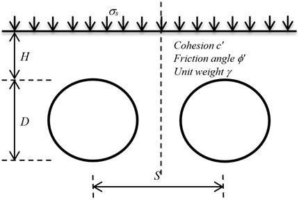
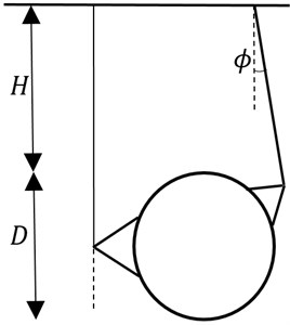
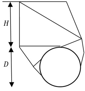
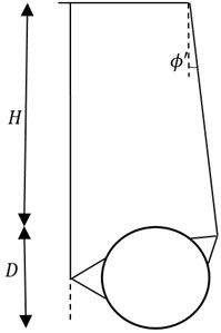
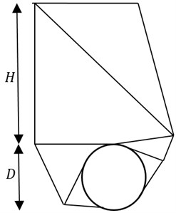
The twin circular tunnels which have diameter , depth and distance between the tunnels are illustrated as in Fig. 1. The ground deformation takes place under plane strain. The soil is assumed to be rigid perfectly plastic and modelled by a Mohr-Coulomb yield criterion with cohesion , friction angle and unit weight . Drained loading conditions are also considered, and surcharge loading is applied to the ground surface. In order to assess the stability of the tunnel, a dimensionless load factor is defined by using a function of , , and , as shown in the following equation:
In order to investigate the stability load factor , the variation in considered parameters are 1-5, 0°-20°, 0-3 and tunnel spacing 1.25-12.5. To describe the smooth interface condition between the loading and the soil, the values of vertical velocities are equal to zero along the ground surface.
Fig. 1Twin circular tunnels subjected to surcharge loading
3. Upper bound limit analysis formulation
Let us consider a rigid-perfectly plastic body of area with boundary , which is subjected to body forces and to surface tractions g on the free portion of . The constrained boundary is fixed and , . Let belongs to a space of kinematically admissible velocity fields, where , are the velocity components in - and - directions, respectively. The strain ratescan be expressed by relations:
The external work rate associated with a virtual plastic flow is given by:
The internal plastic dissipation of the two-dimensional domain can be written as:
The upper bound theorem states that there exists a kinematically admissible displacement field , such that:
where is the axact limit load multiplier of the load , and is the work of additional , not subjected to the multiplier.
Letting the collapse load multiplier can be determined by the following formulae:
4. Brief on the node-based smoothed finite element method (NS-FEM)
The idea of the nodal integration in meshfree method using the strain smoothing technique was proposed by Chen and co-workers [24, 25]. Later, Liu and collaborators [26-31] applied this technique to standard FEM to provide a softening effect to improve the solution of FEM, which is called smoothed finite element method (S-FEM), such as ES-FEM, CS-FEM, NS-FEM, and so on. The main difference between S-FEM and the standard FEM is the strain field. In standard FEM, the displacement field is assumed, and the strain is calculated from the strain-displacement relation. In S-FEM, a strain smoothing is calculated from the strain in FEM by a smoothed function. In this paper, the formulation of smoothing function using NS-FEM is presented.
Fig. 2Triangular elements and smoothing cells associated with the nodes in the NS-FEM
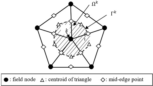
In NS-FEM, the integration based on nodes and strain smoothing technique [24, 25] is used. The problem domain is divided into smoothing cells associated with the node such that and , and is the total number of field nodes located in the entire problem domain. Each triangular element will be divided into three quadrilateral sub-domain and each quadrilateral sub-domain is attached with the nearest field node.
A strain smoothing formulation on the cell is now defined by the following operation:
where is a smoothing function that satisfies positive and normalized to unity:
The smoothing function is assumed constant:
where is the area of the cell and the smoothed strain on the domain can be expressed as:
where is the boundary of the domain as shown in Fig. 2 and is a matrix with components of the outward normal vector on the boundary given by:
The smoothed strain on the cell associated with node can be calculated by:
where is the set containing nodes that are directly connected to node , is the nodal displacement vector and the smoothed strain gradient matrix on the domain can be determined from:
where:
When a linear compatible displacement field along the boundary is used, one Gauss point is sufficient for line integration along each segment of boundary of , the above equation can be determined from:
where is the total number of the boundary segment of , is the Gauss point of the boundary segment of which has length and outward unit normal .
5. NS-FEM formulation for plane strain with Mohr-Coulomb yield criterion
The soil is assumed to be perfectly plastic, and it obeys the Mohr-Coulomb failure criterion and associated flow rule. The Mohr-Coulomb yield function can be expressed in the form of stress components as:
For an associated flow rule, the direction of the plastic strain rates vector is given by the gradient to the yield function, with its magnitude given by the plastic multiplier rate :
Therefore, the power of dissipation can be formulated as a function of strain rates for each domain is presented in [41]:
where is the area of the element of node , is a vector of additional variables defined by:
The change volume after deformation in cohesive-frictional soil can be calculated from:
Introducing an approximation of the displacement and the smoothed strains rates can be calculated from Eq. (13), the upper-bound limit analysis problem for plane strain using NS-FEM can be determined by minimizing the objective function:
where is the total number of nodes in domain.
The fourth constraint in Eq. (24) is a form of quadratic cones.
6. Numerical results
Due to symmetry, only half of the problem is considered. In this paper, GiD [42] is employed for automatic mesh generation with three node triangular elements and adaptive refinement along the periphery of the tunnel. The size of domain is chosen sufficiently large enough to ensure that the failure mechanism only taking place inside the considered domain. For the case of 1 and 2, the typical finite element meshes of 1672 triangular elements are employed in numerical analysis as shown in Fig. 3.
Fig. 3Typical NS-FEM meshes for twin circular tunnels (H/D= 1, S/D= 2)
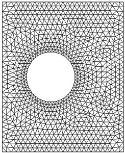
Fig. 4Deformed meshes (H/D= 1, S/D= 2)
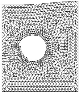
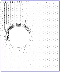
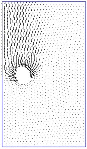
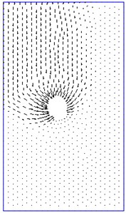
Fig. 5Velocity plot (H/D= 1, S/D= 2)
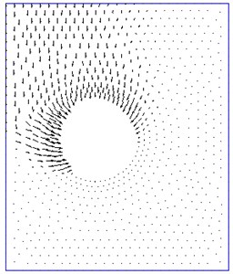
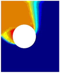
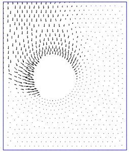
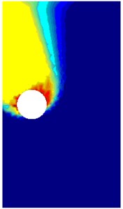
Fig. 6The comparison between rigid-block mechanism and failure mechanism obtained by this method NS-FEM. For the case: H/D= 1, γD/c'= 1, S/D= 1.5, ϕ'= 10, smooth interface
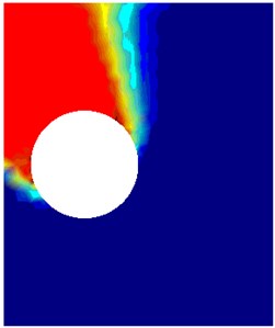
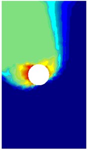
a) Power dissipation 0.74
b) Velocity plot
c) Rigid-block mechanism 0.83
Figs. 6-9 illustrate the failure mechanisms and velocity plots for various cases of twin tunnels. Fig. 6(a) shows the power dissipation of twin circular tunnels for shallow tunnel in the case that friction angle and spacing ratio are relatively small. It is noticeable that a small slip failure occurs between twin tunnels and a large failure domain extends up to the ground surface. Fig. 7(a) shows the case for shallow depth, moderate friction angle and small distance between dual tunnels . In this figure, a small slip surface between two circular tunnels enlarges to the top and bottom of tunnels and a large surface from the middle part of the tunnel extends up to the ground surface. The power dissipations obtained in this study are quite identical to those which were derived from rigid block technique proposed by Chen [43] and solution of Yamamoto et al. [17].
Fig. 7The comparison between rigid-block mechanism and failure mechanism obtained by this method NS-FEM. For the case: H/D= 1, γD/c'= 1, S/D= 2, ϕ'= 20°, smooth interface
a) Power dissipation 2.45
b) Velocity plot
c) Rigid-block mechanism 3.89
Fig. 8The comparison between rigid-block mechanism and failure mechanism obtained by this method NS-FEM. For the case: H/D= 3, γD/c'= 1, S/D= 2, ϕ'= 10°, smooth interface
a) Power dissipation 0.85
b) Velocity plot
c) Rigid-block mechanism 1.39
Figs. 8, 9 show the failure mechanism of twin circular tunnels for moderate depth, small friction angles medium spacing between the tunnels . The slip surface between the tunnels enlarges to the top and bottom of tunnels, a large surface originates the bottom of tunnel extends up to the ground surface. The values of stability number obtained from rigid-block mechanism are slightly greater than those from NS-FEM upper bound solution. The errors stability numbers calculated from NS-FEM limit analysis and Yamamoto et al. [17] in the cases are shown in Figs. 6-9 are 2.6 %, 0.4 %, 4.4 % and 3.7 %, respectively.
In Figs. 6-9, the stability numbers of twin circular tunnels increase when increasing the value of the ratio . When is small enough for two tunnels to interact, the failure mechanism enlarges as and increase. When the distance between two tunnels is large enough, there will be no influence on the failure mechanism of each tunnel. Therefore, the ratio parameter plays an important role in the behaviour of the failure mechanism and the increase of stability number is due to the effects of interaction.
Fig. 9The comparison between rigid-block mechanism and failure mechanism obtained by this method NS-FEM. For the case: H/D= 3, γD/c'= 1, S/D= 3.5, ϕ'= 10°, smooth interface
a) Power dissipation 1.56
b) Velocity plot
c) Rigid-block mechanism 3.02
Fig. 10Numerical results from NS-FEM limit analysis (smooth interface)
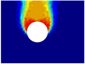
a) Power dissipation: ( 1, 1, 3.5, 10°)
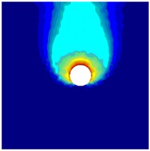
b) Power dissipation: ( 3, 1, 7, 10°
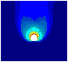
c) Power dissipation: ( 5, 1, 10, 10°
The power dissipations in Fig. 10 show no interaction between dual circular tunnels, and the failure mechanism of two parallel tunnels looks like the case of individual single tunnel. For example, Figs. 10(a)-(c) show that the power dissipations in case the ratio 1, 3,5 and 1, 10°, there is no interaction of twin circular tunnels when 3.5, 7, 10, respectively. To maximize stability number, the twin circular tunnels should be placed far enough apart to ensure no interaction between the tunnels and that stability number is equal to the single circular tunnel.
To evaluate the accuracy of this research, the obtained results and those of Yamamoto et al [17] were plotted in Figs. 11-13. These figures show that the results derived from this proposed method are very good because most of them are lower than upper bound solutions of Yamamoto et al. [17] and higher than Yamamoto’s lower bound solution. As shown in Figs. 11 and 12, stability numbers decrease when increasing the value of the ratio , its mean that the weight of the soil effects to the failure mechanism of twin circular tunnels.
Fig. 13 presents the results of stability numbers for deep tunnels 5. In this figure, when the ratio increases from 1.25 to 3, the stability numbers slightly decrease. This is because of the fact that when the two tunnels are very close together, the extra resistance gained by increasing the width of the pillar is not enough to be the counterbalance of the extra soil mass that it must support. Increasing further, the stability numbers tend to become constant when the space between the tunnels exceeds a certain value. At this point, the failure mechanisms become two individual single tunnels.
Fig. 11Comparisons of the stability numbers between present method and Yamamoto et al. [17] For the case H/D= 1, smooth interface
![Comparisons of the stability numbers between present method and Yamamoto et al. [17] For the case H/D= 1, smooth interface](https://static-01.extrica.com/articles/17896/17896-img21.jpg)
a) 5°
![Comparisons of the stability numbers between present method and Yamamoto et al. [17] For the case H/D= 1, smooth interface](https://static-01.extrica.com/articles/17896/17896-img22.jpg)
b) 10°
![Comparisons of the stability numbers between present method and Yamamoto et al. [17] For the case H/D= 1, smooth interface](https://static-01.extrica.com/articles/17896/17896-img23.jpg)
c) 15°
![Comparisons of the stability numbers between present method and Yamamoto et al. [17] For the case H/D= 1, smooth interface](https://static-01.extrica.com/articles/17896/17896-img24.jpg)
d) 20°
![Comparisons of the stability numbers between present method and Yamamoto et al. [17] For the case H/D= 1, smooth interface](https://static-01.extrica.com/articles/17896/17896-img25.jpg)
The values of stability numbers obtained by using NS-FEM and SOCP are summarized in Table A1 (in Appendix). As expected, when the space between twin tunnels exceeds a certain value, the stability load factor tends to become constant. The negative results imply that a tensile normal stress can be applied to the ground surface to ensure that there is no collapse occurred, but this cannot be seen in engineering practice. The positive one means that the tunnel will be collapsed when it is subjected a compressive stress on the ground surface as this value. The stability numbers at the no-interaction points for twin circular tunnels are highlighted in bold. When the spacing between the tunnels exceeds these points, the values obtained from NS-FEM tend to become constant. In cases of 5 and 3, the stability numbers that approximate zero are indicated by “–“, it means that the tunnels collapse under the weight of the soil.
Fig. 12Comparisons of the stability numbers between present method and Yamamoto et al. [17]. For the case H/D= 3, smooth interface
![Comparisons of the stability numbers between present method and Yamamoto et al. [17]. For the case H/D= 3, smooth interface](https://static-01.extrica.com/articles/17896/17896-img26.jpg)
a) 5°
![Comparisons of the stability numbers between present method and Yamamoto et al. [17]. For the case H/D= 3, smooth interface](https://static-01.extrica.com/articles/17896/17896-img27.jpg)
b) 10°
![Comparisons of the stability numbers between present method and Yamamoto et al. [17]. For the case H/D= 3, smooth interface](https://static-01.extrica.com/articles/17896/17896-img28.jpg)
c) 15°
![Comparisons of the stability numbers between present method and Yamamoto et al. [17]. For the case H/D= 3, smooth interface](https://static-01.extrica.com/articles/17896/17896-img29.jpg)
d) 20°
![Comparisons of the stability numbers between present method and Yamamoto et al. [17]. For the case H/D= 3, smooth interface](https://static-01.extrica.com/articles/17896/17896-img30.jpg)
It is clearly that this numerical method gives a very good solution because most of obtained results are between those derived from lower bound (LB) and upper bound (UB) solutions given by Yamamoto et al. [17]. More interestingly, the total number of elements in the meshes used in the upper bound limit analysis ranges from 1672 to 3075 triangular elements (NS-FEM), while there is a significantly larger number of elements employed in Yamamoto’s models (7680 triangular elements and 11412 stress/velocity discontinuities). The convergence of the method is examined in the stability analysis of dual circular tunnels for the case of 1, 1, 1.25, 5° with a various number of elements in simulated model, and the results are summarized in Table 1. In comparison with those of Yamamoto et al. [17], it is recognized that the numerical procedure using NS-FEM and SOCP not only reduces an appreciable amount of variables in optimization problem, but also gives a very better solution.
Fig. 13Comparisons of the stability numbers between present method and Yamamoto et al. [17]. For the case H/D= 5, smooth interface
![Comparisons of the stability numbers between present method and Yamamoto et al. [17]. For the case H/D= 5, smooth interface](https://static-01.extrica.com/articles/17896/17896-img31.jpg)
a) 5°
![Comparisons of the stability numbers between present method and Yamamoto et al. [17]. For the case H/D= 5, smooth interface](https://static-01.extrica.com/articles/17896/17896-img32.jpg)
b) 10°
![Comparisons of the stability numbers between present method and Yamamoto et al. [17]. For the case H/D= 5, smooth interface](https://static-01.extrica.com/articles/17896/17896-img33.jpg)
c) 15°
![Comparisons of the stability numbers between present method and Yamamoto et al. [17]. For the case H/D= 5, smooth interface](https://static-01.extrica.com/articles/17896/17896-img34.jpg)
d) 20°
![Comparisons of the stability numbers between present method and Yamamoto et al. [17]. For the case H/D= 5, smooth interface](https://static-01.extrica.com/articles/17896/17896-img35.jpg)
Fig. 14The convergence of stability factors of twin circular tunnels. For the case: H/D= 1, S/D= 1.25 and ϕ'= 5°
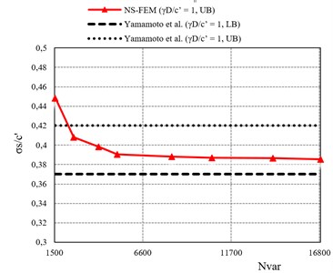
Table 1The computational efficiency of present method using NS-FEM and SOCP. For the case: H/D= 1, γD/c'= 1, S/D= 1.25, ϕ'= 5°
0.4483 | 0.4081 | 0.3983 | 0.3906 | 0.3882 | 0.3871 | 0.3864 | 0.3856 | |
Ne | 523 | 914 | 1460 | 1935 | 3075 | 3975 | 5340 | 6408 |
Nvar | 1555 | 2615 | 4060 | 5130 | 8270 | 10595 | 14110 | 16850 |
Iteration | 17 | 18 | 20 | 20 | 20 | 21 | 20 | 20 |
Mosek time (s) | 0.41 | 0.69 | 1.19 | 1.58 | 2.89 | 4.34 | 6.57 | 8.11 |
Ne = no. of elements, Nvar = no. of variables | ||||||||
7. Conclusions
In this paper, a numerical procedure based on the node-based smoothed finite element method (NS-FEM) is proposed to evaluate the stability of a plane strain twin circular tunnels in cohesive-frictional soil subjected to surcharge loading. The obtained results are in well agreement with the average values of the lower bound and upper bound reported by Yamamoto et al. [17]. The ratio plays an important role in the failure mechanism of twin circular tunnels. To maximize stability number, the distance between the twin circular tunnels should be large enough to ensure no interaction between them and the stability number approaches the value of the single circular tunnel. Various numerical examples for twin circular tunnel problems have been carried out showing that the presented method is able to provide accurate and stable solutions with minimal computational effort. It is promising to develop the proposed method for more complex and large scale problems.
References
-
Atkinson J. H., Cairncross A. M. Collapse of a Shallow Tunnel in a Mohr-Coulomb Material. Role of Plasticity in Soil Mechanics, Cambridge, 1973, p. 202-206.
-
Cairncross A. M. Deformation Around Model Tunnels in Stiff Clay. Ph.D. Thesis, University of Cambridge, 1973.
-
Seneviratne H. N. Deformations and Pore-Pressures Around Model Tunnels in Soft Clay. Ph.D. Thesis, University of Cambridge, 1979.
-
Mair R. J. Centrifugal Modelling of Tunnel Construction in Soft Clay. Ph.D. Thesis, University of Cambridge, 1979.
-
Davis E. H., Gunn M. J., Mair R. J., Seneviratne H. N. The stability of shallow tunnels and underground openings in cohesive material. Geotechnique, Vol. 30, Issue 4, 1980, p. 397-416.
-
Mühlhaus H. B. Lower bound solutions for circular tunnels in two and three dimensions. Rock Mechanics and Rock Engineering, Vol. 18, 1985, p. 37-52.
-
Leca E., Dormieux L. Upper and lower bound solutions for the face stability of shallow circular tunnels in frictional material. Geotechnique, Vol. 40, Issue 4, 1990, p. 581-606.
-
Sloan S. W., Assadi A. Undrained stability of a square tunnel in a soil whose strength increases linearly with depth. Computers and Geotechnics, Vol. 12, Issue 4, 1991, p. 321-346.
-
Lyamin A. V., Sloan S. W. Stability of a plane strain circular tunnel in a cohesive frictional soil. Proceedings of the J. R. Booker Memorial Symposium, Sydney, Australia, 2000, p. 139-153.
-
Lyamin A. V., Jack D. L., Sloan S. W. Collapse analysis of square tunnels in cohesive-frictional soils. Proceedings of the First Asian-Pacific Congress on Computational Mechanics, Sydney, Australia, 2001, p. 405-414.
-
Yamamoto K., Lyamin A. V., Wilson D. W., Sloan S. W., Abbo A. J. Stability of a single tunnel in cohesive-frictional soil subjected to surcharge loading. Canadian Geotechnical Journal, Vol. 48, Issue 12, 2011, p. 1841-1854.
-
Yamamoto K., Lyamin A. V., Wilson D. W., Sloan S. W., Abbo A. J. Stability of a circular tunnel in cohesive-frictional soil subjected to surcharge loading. Computers and Geotechnics, Vol. 38, Issue 4, 2011, p. 504-514.
-
Soliman E., Duddeck H., Ahrens H. Two- and three-dimensional analysis of closely spaced double-tube tunnels. Tunnelling and Underground Space Technology, Vol. 8, 1993, p. 13-18.
-
Wu B. R., Lee C. J. Ground movements and collapse mechanisms induced by tunneling in clayey soil. International Journal of Physical Modelling in Geotechnics, Vol. 3, 2003, p. 15-29.
-
Chehade F. H., Shahrour I. Numerical analysis of the interaction between twin tunnels: influence of the relative position and construction procedure. Tunnelling and Underground Space Technology, Vol. 23, 2008, p. 210-214.
-
Osman A. S. Stability of unlined twin tunnels in undrained clay. Tunnelling and Underground Space Technology, Vol. 25, 2010, p. 290-296.
-
Yamamoto K., Lyamin A. V., Wilson D. W., Sloan S. W., Abbo A. J. Stability of dual circular tunnels in cohesive-frictional soil subjected to surcharge loading. Computers and Geotechnics, Vol. 50, 2013, p. 41-54.
-
Hughes T. J. R. Reduced and selective integration techniques in the finite element analysis of plates. Nuclear Engineering and Design, Vol. 46, 1978, p. 203-222.
-
Hughes T. J. R. The finite Element Method. Dover Publications, Prentice-Hall, 2000.
-
Piltner R., Taylor R. L. Triangular finite elements with rotational degrees of freedom and enhanced strain modes. Computers and Structures, Vol. 75, 2000, p. 361-368.
-
Simo J. C., Rifai M. S. A class of mixed assumed strain methods and the method of incompressible modes. International Journal for Numerical Methods in Engineering, Vol. 29, 1990, p. 1595-1638.
-
Cardoso R. P. R., Yoon J. W., Mahardika M., Choudhry S., Alves de Sousa R. J., Fontes Valente R. A. Enhanced assumed strain (EAS) and assumed natural strain (ANS) methods for one-point quadrature solid-shell elements. International Journal for Numerical Methods in Engineering, Vol. 75, 2008, p. 156-187.
-
Bonet J., Burton A. J. A simple average nodal pressure tetrahedral element for incompressible and nearly incompressible dynamic explicit applications. Communications in Numerical Methods in Engineering, Vol. 14, 1998, p. 437-449.
-
Chen J. S., Wu C. T., Yoon S. A stabilized conforming nodal integration for Galerkin meshfree method. International Journal for Numerical Methods in Engineering, Vol. 50, 2001, p. 435-466.
-
Yoo J. W., Moran B., Chen J. S. Stabilized conforming nodal integration in the natural-element method. International Journal for Numerical Methods in Engineering, Vol. 60, 2004, p. 861-890.
-
Liu G. R., Nguyen-Thoi T. Smoothed finite Element Methods. CRC Press, New York, 2010.
-
Liu G. R., Dai K. Y., Nguyen-Thoi T. A smoothed finite element for mechanic problems. Computer and Mechanics, Vol. 39, 2007, p. 859-877.
-
Liu G. R., Nguyen-Thoi T., Nguyen-Xuan H., Lam K. Y. A node based smoothed finite element method (NS-FEM) for upper bound solution to solid mechanics problems. Computer and Structures, Vol. 87, 2009, p. 14-26.
-
Nguyen-Thoi T., Liu G. R., Lam K. Y., Zhang G. Y. A face-based smoothed finite element method (FS-FEM) for 3D linear and nonlinear solid mechanics problems using 4-node tetrahedral elements. International Journal for Numerical Methods in Engineering, Vol. 78, 2009, p. 324-353.
-
Liu G. R., Nguyen-Thoi T., Lam K. Y. An edge-based smoothed finite element method (ES-FEM) for static, free and forced vibration analyses of solids. Journal of Sound and Vibration, Vol. 320, 2009, p. 1100-1130.
-
Liu G. R., Nguyen-Thoi T., Dai K. Y., Lam K. Y. Theoretical aspects of the smoothed finite element method (SFEM). International Journal for Numerical Methods in Engineering, Vol. 71, 2007, p. 902-930.
-
Liu G. R., Nguyen-Xuan H., Nguyen-Thoi T. A theoretical study of S-FEM models: properties, accuracy and convergence rates. International Journal for Numerical Methods in Engineering, Vol. 84, 2010, p. 1222-1256.
-
Nguyen-Xuan H., Rabczuk T., Nguyen-Thoi T., Tran T. N., Nguyen-Thanh N. Computation of limit and shakedown loads using a node-based smoothed finite element method. International Journal for Numerical Methods in Engineering, Vol. 90, 2012, p. 287-310.
-
Le C. V., Nguyen-Xuan H., Askes H., Bordas S., Rabczuk T., Nguyen-Vinh H. A cell-based smoothed finite element method for kinematic limit analysis. International Journal for Numerical Methods in Engineering, Vol. 83, 2010, p. 1651-1674.
-
Nguyen-Xuan H., Liu G. R. An edge-based finite element method (ES-FEM) with adaptive scaled-bubble functions for plane strain limit analysis. Computer Methods in Applied Mechanics and Engineering, Vol. 285, 2015, p. 877-905.
-
Nguyen-Xuan H., Rabczuk T. Adaptive selective ES-FEM limit analysis of cracked plane-strain structures. Frontiers of Structural and Civil Engineering, Vol. 9, 2015, p. 478-490.
-
Nguyen-Xuan H., Wu C. T., Liu G. R. An adaptive selective ES-FEM for plastic collapse analysis. European Journal of Mechanics – A/Solid, Vol. 58, 2016, p. 278-290.
-
The MOSEK Optimization Toolbox for MATLAB Manual. http://www.mosek.com.
-
Jagdish Prasad Sahoo, Jyant Kumar Stability of long unsupported twin circular tunnels in soils. Tunnelling and Underground Space Technology, Vol. 38, 2013, p. 326-335.
-
Wilson D. W., Abbo A. J., Sloan S. W., Lyamin A. V. Undrained stability of dual circular tunnels. International Journal of Geomechanics, Vol. 14, 2014, p. 69-79.
-
Makrodimopoulos A., Martin C. M. Upper bound limit analysis using simplex strain elements and second-order cone programming. International Journal for Numerical and Analytical Methods in Geomechanics, Vol. 31, 2006, p. 835-865.
-
GiD 11.0.4, Reference Manual. International Center for Numerical Methods in Engineering (CIMNE), http://www.cimne.com.
-
Chen W. F. Limit Analysis and Soil Plasticity. Elsevier, Amsterdam, 1975.
Cited by
About this article

This research was partially supported by the Foundation for Science and Technology at HCMUT University of Technology (Grant No. TNCS-2015-KTXD-09). We sincerely appreciate Dr. Canh V. Le for sharing the upper bound analysis code. This support is gratefully acknowledged.
