Abstract
In order to investigate the effect of inlet splitter on pressure fluctuations in a double-suction centrifugal pump, three research schemes, including no splitter (scheme I), a splitter along the flow passage centerline (scheme II) and a splitter above the flow passage centerline in the suction (scheme III), were designed. The flow in the pump was simulated by commercial code FLUENT. The viscous Navier-Stokes equations were handled with an unsteady calculation and the sliding mesh technique was applied to take into account the impeller-volute interaction. Based on the simulation results, the hydraulic performance and pressure fluctuations were obtained and analyzed in detail. The hydraulic performance agrees well with the experimental results. The pressure fluctuations under three schemes are different. The maximum amplitude of the pressure fluctuations in scheme II is the minimum. For monitoring points near volute tongue, rotating frequency and its harmonies are dominant under three research schemes. The maximum amplitude of pressure fluctuations of three schemes are all at the blade passing frequency. In particular, the maximum pressure fluctuation amplitude of scheme II was less than that of scheme I and scheme III, which illustrated that it is effective to reduce the peak value of pressure fluctuations in double suction centrifugal pump by installing a splitter in the suction properly.
1. Introduction
Flow in centrifugal pumps is very complex and unsteady [1]. The unsteady flow, especially at off-design condition, would result in pressure fluctuation, which is very harmful for pump operation [2]. So, it is necessary to research the pressure fluctuations centrifugal pumps to improve its stability.
At present, two methods, experimental test and numerical simulation, are used to investigate the unsteady pressure pulsations in pumps. Although experimental test is reliable, it is very difficult to measure the pressure pulsations in pumps and high cost and more time will be wasted in it. With the rapid development of CFD technology, numerical simulation has gradually become the main method to research the inner flow in pumps. It is very useful and convenient to predict pressure pulsations.
Gonzalez and Chu [3, 4] pointed out that the interaction between the impeller and volute tongue has important effect on pressure fluctuation. Wang [5] performed the experiment of pressure fluctuation and vibration in a mixed flow pump and pointed that the peak value of pressure fluctuation peak was decreased gradually with the increase of flow rate. Jiang [6] investigated the relative position between volute tongue and diffuser vanes by CFD and pointed out that when volute tongue was located near the middle of two diffuser vanes, the peak value of pressure fluctuation was minimum. Yao [7] researched the effect of impeller blade distribution on the pressure fluctuation in a double suction pump and point out that pressure fluctuation can be reduced if the blade was staggered arrangement on the two sides of the double suction impeller. Jiang [8] analyzed pressure fluctuations in a centrifugal pump under different oblique angles of blade trailing edge according to the simulation results. Zhang [9] researched the effect of slope volute on pressure pulsation in a centrifugal pump. Parrondo [10] also investigated the effect of operation point on pressure pulsation in a centrifugal pump, and particular attention was paid to pressure amplitude at blade passing frequency. Yang [11, 12] pointed out it is an effective measure for reducing pressure pulsation to increase blade tip clearance. Several methods have been introduced to reduce the rotor-stator interaction, including the splitter blade and optimal design of the impeller and volute [13]. Based on a mixed SAS turbulent model, Si et al. [14] investigated pressure pulsation intensity in a centrifugal pump.
Although many literatures are listed on pressure pulsation in centrifugal pumps, all the researches mainly pay attention to the effect of impeller, volute and blade tip clearance. Up to now, there is little research about the effect of suction on pressure fluctuations in a double-suction centrifugal pump. Therefore, this paper focuses on the effect of inlet splitter on pressure fluctuation in a double suction centrifugal pump.
2. Research model, experimental tests and scheme
2.1. Research model and experimental tests
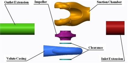
The research model consists of a double inlet impeller, a spiral volute and a suction chamber. The details of geometrical and operating parameters for the model pump are summarized in Table 1, and its structure is shown in Fig. 1.
Due to its high shaft power (about 1800 kW at rated flow), the model pump was tested under low speed and was driven by a variable speed electric AC motor controlled by a frequency converter. The pump performance was tested in the closed test rig schematized in Fig. 2(a). The water was pumped from and returned to a 125 m3 reservoir. The shaft torque and rotational speed were monitored by a torque and speed sensor with errors under ±0.10 %. Static pressure values were measured at the inlet and outlet of the pump by a differential pressure transfer, and the uncertainty was within ±0.10 %. The flow rate was measured by using a magnetic flow meter with the uncertainty less than ±0.14 %. The measurement accuracy of pump efficiency was quantified as ±0.30 %. The scheme of the test rig and the site test of pump are shown in Fig. 2.
Fig. 1Assembly drawing of the double suction pump
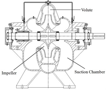
Fig. 2Scheme of the test rig and the site test
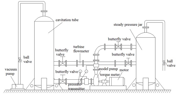
a) Scheme of the test rig
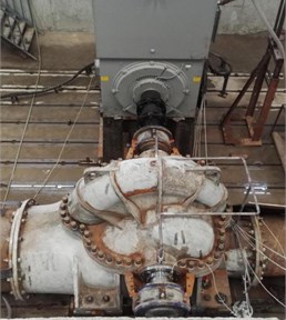
b) The site test
2.2. Scheme
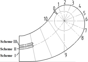
Three research schemes were designed to study the effect of the splitter in suction of the double-suction centrifugal pump on pressure fluctuation. All research schemes are shown in Fig. 3. No splitter in the suction inlet was scheme Ⅰ. In scheme Ⅱ, there is a splitter along the centerline of flow passage in the suction. And in scheme Ⅲ, the location of the splitter is 0.06 m higher than the one of scheme Ⅱ. In order to reduce the effect of the shape and length, the splitter in scheme Ⅲ is the same as the one in scheme II.
Table 1Pump main dimensions
Specific speed | 96 |
Nominal flow rate | 4600 m3/h |
Head at nominal flow rate | 94 m |
Rotational speed | 980 r/min |
Impeller outlet diameter | 0.9 m |
Outlet blade angle | 28 deg |
Outlet impeller width | 0.106 m |
Number of blades | 6 |
Base diameters of volute | 0.95 m |
Inlet diameter | 0.6 m |
Fig. 3Sketch of three research schemes
3. Mathematical model and numerical model
3.1. Mathematical model
Due to the complex geometry of the impeller, the asymmetric geometry of the volute case, the fluid viscosity and the rotor-stator interaction between the impeller and the casing, extremely complex turbulent flows are in pumps. For unsteady flow of incompressible fluid, the equation of continuity equation and moment conservation equations can be written as follows:
where is the static pressure, is the density and (1, 2, 3) is fluid velocity. is the molecular viscosity, is Reynolds stress.
Two-equation turbulence models allow the determination of both, a turbulent length and time scale by solving two separate transport equations. The RNG - was adopted in the research. The turbulence kinetic energy, , and its rate of dissipation, , are obtained from the following transport equations:
In these equations, represents the generation of turbulence kinetic energy due to the mean velocity gradients. This term may be defined as . is the generation of turbulence kinetic energy due to buoyancy and is given by . represents the contribution of the fluctuating dilatation in compressible turbulence to the overall dissipation rate, which is defined as , where is the turbulent Mach number, defined as , and is the speed of sound. The quantities and are the inverse effective Prandtl numbers for and , respectively. and are user-defined source terms, 1.42, 1.68.
3.2. Geometry and grid
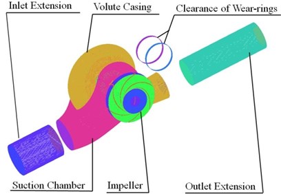
Fluid domains of physical model were built by Creo 2.0. The discretization of the geometry was generated by the GAMBIT pre-process code. Extended section of suction inlet and volute outlet was built to reduce the effect of boundary conditions. The whole flow passage model was employed in order to calculate actual situation accurately. For grid generation, the pump was divided into six components. These six components are: (1) inlet extension, (2) volute casing, (3) clearance of wear-rings, (4) suction chamber, (5) impeller, (6) outlet extension. Structured hexahedral cells are generated to define the inlet, outlet and wear-rings clearance zones while unstructured tetrahedral cells are used to define the impeller, section chamber and volute. Computational model and mesh of the double suction pump are shown in Fig. 4.
Taking the gird of scheme I as an example, and the head prediction as the standard, grid independency studies of scheme I was done by 4 kinds of different mesh density, Table 2 showed that by increasing the number of cells from 4.6×10⁶ to 6.1×10⁶, the variation of head predicted by four kinds of mesh density is about 0.4 %. So, the numerical results of scheme I can be considered as grid independent due to the little difference of predicted head. To take into account the computational resources and keep time costs under control, grid 1 was adopted to simulate.
Table 2Grid independency
Grid1 | Grid2 | Grid3 | Grid4 | |
Inlet extension | 389120 | 389120 | 389120 | 389120 |
Suction chamber | 1902205 | 1902205 | 1902205 | 1902205 |
Clearance of wear-rings | 12800 | 12800 | 12800 | 12800 |
Impeller | 1047949 | 1567669 | 2127446 | 2504984 |
Volute | 1334968 | 1334968 | 1334968 | 1334968 |
Outlet extension | 501900 | 501900 | 501900 | 501900 |
Total grid | 4687042 | 5206762 | 5766539 | 6144077 |
Relative value of head | 1 | 0.99587 | 0.99763 | 0.99667 |
3.3. Boundary condition and solution method
The inlet boundary condition is set to be velocity-inlet, whose value can be given through the ration of flow rate and inlet area. The outflow boundary condition is assumed to be fully development flow, which means that the velocity distribution is uniform along the flow direction. The turbulent kinetic energy and the turbulence dissipation ε are provided directly.
Sliding mesh was used to define the interface between rotation impeller and stationary volute [15]. The no-slip condition was imposed in all the walls of the model. The standard wall function was used to solve the low Reynolds number flow in the near wall region.
The flow in the model pump was simulated by the commercial code Fluent, which use the finite volume method to solve the Reynolds averaged Navier-Stokes equations for 3D incompressible unsteady flow. Turbulence is simulated with the RNG - model. Second order upwind discretization was used to the convective and diffusive terms. The time dependent term scheme was second order implicit [16]. The pressure-velocity coupling was calculated by SIMPLEC algorithm.
Initializing the unsteady calculation with the steady solution, over 5 impeller revolutions are necessary to achieve the periodic unsteady solution convergence. In order to get enough time resolution for the dynamic analysis, the time step used in the unsteady calculation was set to be 1.6667×10⁻⁴ s, which is 1/360 of impeller rotational period. For each time step, the convergence criterion was established in a value of 10-4 for the scaled residuals.
Fig. 4Computational model and mesh of the double suction pump
4. Results and discussion
4.1. Performance analysis
In order to verify the credibility of the numerical model, an experimental measurement for pump performance, including head and efficiency, is made (shown in Fig. 5).
Fig. 5Comparison of the performance curves
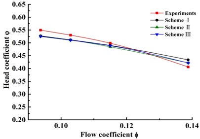
a) Flow head curve
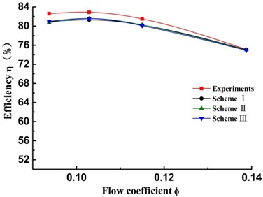
b) Flow efficiency curve
Fig. 5(a) compares the numerical head-capacity curve of three research schemes with the experimental head-capacity curve (no splitter). Good agreement of the head between calculated and experimental can be observed. The predicted head of scheme I is slightly lower than that of experimental ones under the low flow rate. The predicted head is higher than that of the experiment ones under the large flow rate. The relative head error between calculation and experiment values is less than 5 % under the low flow rate. Fig. 5(b) compares the numerical efficiency-capacity curves of three research schemes with the experimental head-capacity curve (no splitter). Under each of operating points, the predicted efficiency of scheme I is slightly lower than that of experimental one. The maximum absolute error value of efficiency is no more than 2.1 %. It indicates that the calculation is feasible for the double suction pump and can be used to perform detail analysis.
In addition, for three research schemes, variation trend of performance curves are almost agreement. Comparing with head and efficiency in three research schemes respectively, the errors of head and efficiency are all less 1 % at each operating points. It shows that the splitter in suction inlet has little effect on performance of the double suction pump.
4.2. Analysis on static pressure and pressure fluctuation
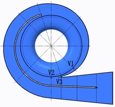
In order to investigate the effect of inlet splitter on static pressure and pressure pulsation in chamber and volute of double suction pump, eight monitoring points was set (five monitoring points in suction and three monitoring points in volute). The symmetry plane (0) was set to be the reference for other planes, as shown in Fig. 6. Impeller inlet was in plane 0.21. Five monitoring points in chamber were all in plane 0.3 m. S1 is near the end of splitter, and monitoring S3 and S4 are near the tongue of suction chamber. S2 and S5 are symmetrically distributed on both sides of the tongue (Fig. 7). Three monitoring points (V1, V2 and V3) were all in symmetry plane (0). V1 and V2 are on base circle and V3 is near tongue (Fig. 8).
Fig. 6Reference planes for the double suction pump
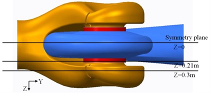
Fig. 7The monitoring points in suction chamber (Z= 0.3 m)
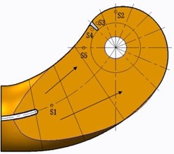
Fig. 8The monitoring points in volute (Z= 0)
4.2.1. Static pressure analysis in suction
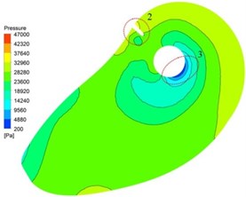
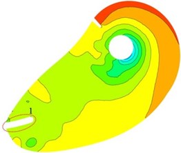
In order to analyze the effect of inlet splitter on static pressure in suction, plane 0.3 m is considered. As shown in Fig. 9, distributions of static pressure under three schemes on plane 0.3 m are uniform. Low pressure area near Central orifice against tongue position is observed. Pressure gradient from inlet to central orifice is uniform change. It can be concluded that the design of suction for the double suction pump is available.
Compared with three research schemes, high pressure concentration appears at tongue position in scheme I and scheme III (location 2). Uniform distribution of averaged static pressure can be observed around central orifice in scheme II. It shows that pressure distribution could be improved by installing a splitter at an appropriate position in suction. At location 3 in scheme I low pressure area is observed, and it does not appear in scheme II and III. It indicates that cavitation performance of double suction pump can be improved by adding a splitter in suction.
Fig. 9Distribution of static pressure on plane Z= 0.3 m
a) Scheme I
b) Scheme II
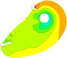
c) Scheme II
4.2.2. Analysis of peripheral velocity in suction
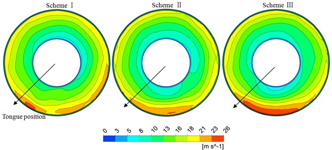
Plane 0.21 is considered to analyze the effect of inlet splitter on peripheral velocity in impeller inlet, as shown in Fig. 10. Distribution of peripheral velocity under three schemes is all consistent. Gradually increasing of velocity gradient along the radius around peripheral direction is observed. It shows that forced vortex theory is well satisfied, which means that with the increase of the radius, the velocity increases gradually. High velocity region is shown at bottom right of tongue position.
Compared with three schemes, high velocity region at bottom right of tongue position in scheme II is minimum, which means the pre-rotation is smallest. It can be concluded that it is advantageous for peripheral velocity in impeller inlet by installing an inlet splitter at an appropriate position.
Fig. 10Peripheral velocity on plane Z= 0.21 m
4.2.3. Analysis of pressure fluctuation in suction
Because of the unsteady rotor-stator interference between the impeller and the volute, the pressure changes rapidly with the time in pumps, that is, the pressure pulsation. Pressure fluctuation coefficient is a physical quantity to characterize the magnitude of pressure fluctuation. Fig. 11 shows the pressure pulsation of each monitoring point under design flow rate in a impeller rotation period. axis in the coordinate system shows time, and axis is the pressure fluctuation coefficient , whose calculation formula is:
Fig. 11Pressure fluctuations of monitoring points for three schemes
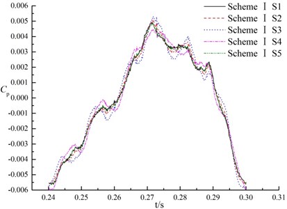
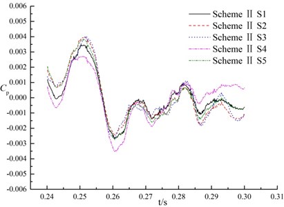
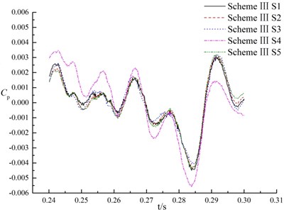
As can be observed in Fig. 11, with time variation the pressure fluctuations for three research schemes are complicate. For the same monitoring points in the difference scheme, the pressure pulsation is different at all. The maximum fluctuation amplitude of scheme I is at 0.27117 s, which is at a period of about 1/2 cycles. Maximum amplitude of pressure fluctuations in scheme II appears at the period of about 1/6 cycles, and that of scheme III appears at a period of about 5/6 cycles. It can be concluded that amplitude period of pressure fluctuation is affected by splitter directly.
For the same monitoring points, the maximum amplitude in pressure fluctuations of scheme II was 0.59 times than that of scheme I, and 0.89 times than that of scheme III, that is, the amplitude of pressure fluctuations in suction in scheme II is less than scheme I and scheme III. It means that the splitter along flow passage centerline could reduce the peak value of pressure fluctuations in suction.
For the different monitoring points in the same scheme, the pressure fluctuations are basically the same. Because monitoring point S3 and S4 are near the tongue (shown in Fig. 7), the amplitude of pressure fluctuations at S3 and S4 are more drastic and large than that of the others. It may be caused by the blockage of the tongue in the suction.
Compared with pressure fluctuations of S3 and S4 in different schemes, the pressure fluctuation curve of scheme II and scheme III is more flat than that of scheme I, and the pressure fluctuation amplitude is smaller than that of scheme I.
At monitoring point S3, the maximum fluctuation amplitude of scheme I, scheme II and scheme III are 12410.3 Pa, 7388.8 Pa and 8067 Pa respectively. The maximum amplitude of pressure fluctuations in scheme I is 0.6 times that of scheme II, and 0.91 times that of scheme III. At monitoring point S4, the maximum amplitude of pressure fluctuation in scheme I, scheme II and scheme III are 11674.3 Pa, 6959.1 Pa and 10065.5 Pa respectively. The maximum amplitude of scheme I is 0.59 times that of scheme II, and 0.69 times that of scheme III. The fluctuation amplitude of scheme II is the minimum. It indicates that splitter has a prominent effect to reduce pressure fluctuation near tongue in the suction chamber (scheme II), but it is necessary to pay attention the location of splitter (scheme III).
Compared with monitoring points S1, S2 and S5 in the same scheme, trend of the pressure fluctuations are almost entirely consistent. The relative discrepancy of the maximum fluctuation amplitude is less than 1 %. It can be concluded that in each scheme at nominal flow rate, variation trend of pressure fluctuations along the direction of S1-S5 and S1-S2 are consistent. It means that the effect on the pressure fluctuations is not significant by rotor-stator interaction.
4.2.4. Analysis of pressure fluctuations in volute
Fig. 12 shows the time domain characteristics of the pressure fluctuations at monitoring points V1, V2 and V3 in volute.
Fig. 12Pressure fluctuations of monitoring points in volute
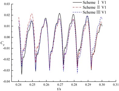
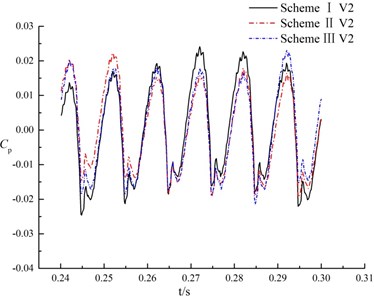
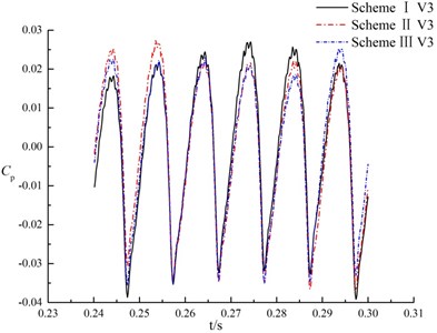
For different monitoring points in the same scheme, pressure fluctuations in a rotation period of impeller present quasi periodic, as shown in Fig. 12. That is, rotor-stator interaction is caused when blade of impeller passes through the tongue. The variation trend and change period of pressure fluctuations are almost consistent at the same monitoring point under different schemes. It indicates that the splitter in suction has no significant effect on pressure fluctuation in volute.
The maximum amplitude of pressure fluctuations at monitoring point V1 under three schemes are 61300.7 Pa, 55550.8 Pa and 57846.1 Pa respectively. The maximum amplitude of pressure fluctuation in scheme II is 0.9 times that of scheme I, and 0.96 times that of scheme III. At the monitoring point V2, scheme II is 0.89 times the maximum amplitude of pressure fluctuations of scheme I, and 0.95 times of scheme III. For the monitoring point V3, the maximum amplitude of pressure fluctuations in scheme II is 0.95 times as much as scheme I, and 0.96 times as much as scheme III, that is, amplitude of pressure fluctuations in scheme II has little diffidence with scheme I and scheme III. It indicates that the splitter in suction has not significant influence on maximum amplitude of pressure fluctuation of tongue in volute.
4.3. Frequency domain analysis of pressure fluctuations in volute
Fig. 13 shows the frequency domain characteristics of the pressure fluctuations at V1, V2 and V3. Fast Fourier transform (FFT) processing is applied to display the unsteady pressure feature in frequency domain.
Fig. 13Frequency domain characteristics of pressure fluctuations in volute
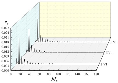
a) Frequency domain characteristics of monitoring point V1
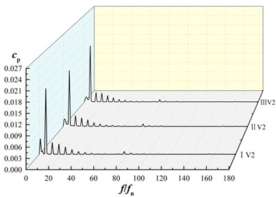
b) Frequency domain characteristics of monitoring point V2
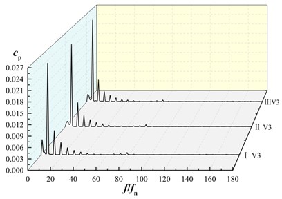
c) Frequency domain characteristics of monitoring point V3
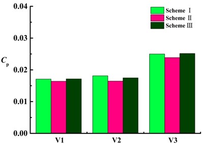
d) Maximum amplitude of pressure fluctuations at V1, V2, V3
For each monitoring point under three schemes, amplitudes of pressure fluctuations appear at the rotating frequency and its harmonic frequency. The maximum amplitude of pressure fluctuation is at blade passing frequency and decrease in turn at its harmonic frequency, as shown in Fig. 13(a)-13(c). For each monitoring point, the maximum amplitude of pressure fluctuations in scheme II is smaller than that of scheme I and scheme III. As shown in Fig. 10(d), at V1, V2, V3, the maximum amplitude of pressure fluctuations in scheme II are 0.95, 0.91 and 0.95 times that of scheme I, 0.96, 0.94, 0.95 times that of scheme III, that is, maximum amplitude of pressure fluctuations in scheme II is almost the same as that of scheme I and that of scheme III, it shows that the splitter has not significant influence on maximum amplitude of pressure fluctuation near volute tongue.
For the same scheme at diffident monitoring point, amplitude of pressure fluctuation at V3 is larger than other monitoring points. That is, pressure fluctuation near tongue is the most violent in volute.
At low frequency region for V1, V2, V3, the maximum amplitude of the pressure fluctuation in scheme II and scheme III is lower than that of scheme I. It indicates that the maximum amplitude of pressure fluctuations at low frequency region in volute is reduced as installing the splitter in suction.
5. Conclusions
In this paper, performance, static pressure and pressure pulsations of double suction pump has been calculated and analyzed. The main conclusions can be taken as follows.
1) Compared experiment results of double suction pump with calculated results, the good agreement is observed. It indicates that performance of the double suction pump could be predicted well by the model pump using commercial code FLUENT.
2) Cavitation performance of double suction pump can be improved by adding a splitter in suction chamber.
3) In suction, variation of pressure fluctuation is basically the same at each monitoring point of the same scheme. In the same monitoring points of different schemes, variation trend of pressure fluctuation is not the same. Amplitude of pressure fluctuation in scheme II is less than other schemes. It is indicated that a splitter distributed in a suction chamber could reduce the peak value of pressure fluctuations of tongue in the suction chamber.
4) In the tongue of volute and its adjacent area, pressure fluctuations of monitoring points in three scheme are presented with quasi periodic variation. Maximum amplitude of pressure fluctuation is induced at blade passing frequency. Maximum amplitude of pressure fluctuation on monitor points V1 V2 V3 in scheme II are 0.95, 0.91, 0.95 times of that of scheme I respectively, 0.96, 0.94, 0.95 times of that of scheme III. It indicates that the splitter distributed in the suction chamber has not significant influence on maximum amplitude of pressure fluctuation of tongue in volute.
References
-
Brennen C. E. Hydrodynamics of Pumps. Oxford University Press and CETI Inc., Oxford, 1994.
-
Pei J., Dohmen H. J., Yuan S. Q., et al. Investigation of unsteady flow-induced impeller oscillations of a single-blade pump under off-design conditions. Journal of Fluids and Structures, Vol. 35, 2012, p. 89-104.
-
Gonzalez J., Santolaria C., Blance E. The influence of volute tongue on the pressure oscillations inside a centrifugal pump. Proceeding of the 21st IAHR Symposium Hydraulic Machinery and System, 2002, p. 847-854.
-
Chu S., Dong R., Katz J. Relationship between unsteady flow, pressure fluctuations, and noise in a centrifugal pump. Part B: Effects of blade-tongue interactions. Journal of Fluids Engineering, Transactions of the ASME, Vol. 117, Issue 1, 1995, p. 30-35.
-
Wang K., Liu H. L., et al. Experimental research on pressure fluctuation and vibration in a mixed flow pump. Journal of Mechanical Science and Technology, Vol. 30, Issue 1, 2016, p. 179-184.
-
Jiang W., Li G. J., et al. Numerical investigation of influence of the clocking effect on the unsteady pressure fluctuations and radial forces in the centrifugal pump with vaned diffuser. International Communications in Heat and Mass Transfer, Vol. 71, 2016, p. 164-171.
-
Yao Z. F., Wang F. J., Yang M., et al. Effects of impeller type on pressure fluctuations in double-suction centrifugal pump. Journal of Mechanical Engineering, Vol. 47, Issue 12, 2011, p. 133-137.
-
Jiang W., Li G. J., Zhang X. S. Effect of oblique angle of blade trailing edge on pressure fluctuation in centrifugal pump. Journal of Drainage and Irrigation Machinery Engineering, Vol. 31, Issue 5, 2013, p. 369-372.
-
Zhang N., Yang M. G., et al. Experimental and numerical analysis of unsteady pressure pulsation in a centrifugal pump with slop volute. Journal of Mechanical Science and Technology, Vol. 29, Issue 10, 2015, p. 4231-4238.
-
Parrondo J. L., González J., Fernández J. The Effect of the operating point on the pressure fluctuations at the blade passage frequency in the volute of a centrifugal pump. Journal of Fluids Engineering, Vol. 124, Issue 3, 2002, p. 784-790.
-
Yang, S. S., Liu, H. L., et al. Effects of the radial gap between impeller tips and volute tongue influencing the performance and pressure pulsations of pump as turbine. Journal of Fluids Engineering, Vol. 136, Issue 5, 2014, p. 054501.
-
Yang S. S., Kong F. Y., Chen H. Effects of blade wrap angle influencing pump as turbine. Journal of Fluids Engineering, Vol. 134, Issue 6, 2012, p. 061102.
-
Cui B. L., Wang C. F., Zhu Z. C., et al. Influence of blade outlet angle on performance of low-specific-speed centrifugal pump. Journal of Thermal Science, Vol. 22, Issue 2, 2013, p. 117-122.
-
Si Q. R., Yuan J. P., et al. Numerical investigation of pressure fluctuation in centrifugal pump volute based on SAS model and experimental validation. Advances in Mechanical Engineering, 2012, p. 972081.
-
Wang F. J. Computational Fluid Dynamics Analysis – CFD Software Principle and Application. Tsinghua University Press, Beijing, 2004.
-
Nere N. K., Patwardhan A. W., Joshi J. B. Prediction of flow pattern in stirred tanks new constitutive equation for eddy viscosity. Industrial and Engineering Chemistry Research, Vol. 40, Issue 7, 2001, p. 1755-1772.
Cited by
About this article
The authors gratefully acknowledge the support from the Foundation of National Natural Science Foundation of China (Grant Nos. 51509109, 51579117, 51279067), Jiangsu Province (Grant Nos. BY2014123-09, BA2013127), and Priority Academic Program Development of Jiangsu Higher Education Institutions (PAPD).
Houlin Liu contributed to the conception of the study; Kaikai Luo performed the data analyses and wrote the manuscript; Xianfang Wu contributed significantly to analysis and manuscript preparation; Huilong Chen helped perform the analysis with constructive discussions; Kai Wang helped carry out experiments.
