Abstract
Vane number is an important parameter of IGV device, which indirectly affects hydraulic performance and pressure pulsation characteristics of the attached pump. In this study, based on an IS pump, the influences of vane number on hydraulic performance and pressure pulsation characteristics were considered. Four set of IGV devices were generated to assemble to the pump with 5, 6, 7 and 9 vanes, respectively. Then the three-dimensional unsteady flow fields were simulated using RNG turbulence model and sliding mesh by Fluent-16.0. The numerical results showed good agreement with the experimental data, which validated the numerical models. The effects of vane number on pump head and efficiency are different. 6 vanes IGV device can produce higher head while 7 or 9 vanes can bring about higher efficiency. Similarly, the influences of vane number on pressure pulsation in time domain and frequency domain are also complex. 6 vanes IGV device can remarkably decrease power spectral density at all flow rate conditions, but 7 vanes IGV device can improve pump pressure pulsation characteristics and realize better hydraulic stability. Therefore, it is hard to determine the best vane number, but 6 vanes IGV device is suggested for engineering application to obtain better hydraulic performance.
1. Introduction
Centrifugal pump is widely applied in petrochemical industry, irrigation, aerospace, urban water supply and drainage, water conservancy, hydropower engineering and other areas of national economy due to its relatively compact structure and wide application field. However in reality, most of the centrifugal pumps run at off-conditions and lead to quite lower efficiency, and thus researching on its energy characteristic is significant [1]. Therefore, in order to improve present state, it is better to look for an efficient and easy pattern to regulate operating conditions.
The pre-whirl regulation technique using inlet guide vane (IGV) has been validated in industry such as centrifugal compressor and fan [2, 3]. Fukutomi and Nakamura [4] installed one set of IGV in tongue division and the performance of the cross-flow fan was higher in pressure and efficiency than the case without the guide vane. Recently, this technique has been gradually introduced into pump system and attracted more attention [5, 6]. Based on the hydrodynamics analysis of fluid flow at impeller inlet, Gui Shaobo et al. [7] proposed one kind of hydraulic design method for IGV and the hydraulic test had been conducted by Cao Shuliang [8]. Zhou et al. [9] also designed two kinds of IGVs and the research implied that compared with no IGV conditions, the pump efficiency had been greatly improved and the power consumption had been reduced significantly. Tan Lei et al. [10-11] systematically investigated the influence of axial distance and pre-whirl angle on pre-whirl regulation for the pump by means of numerical simulation and experiment. Also, the effect of pre-whirl regulation on cavitation performance has been investigated in Ref. [12-14]. In short, the investigations above are limited to hydraulic characteristic and cavitation performance. The effect of pre-whirl regulation on hydraulic stability is rare to see in open literatures.
Pressure pulsation has been considered as one important factor to affect hydraulic stability in fluid machinery. The pressure pulsation can induce noise and vibration to pump system and propagate to the attached piping system, and then effectively reduce pump performance [15]. Thus, illustrating interaction mechanism between impeller and volute or pre-whirl regulation device is really important. Many studies have been conducted on such unsteady flow behavior either by experimental or numerical method. Wang and Tsukamoto [16, 17] studied the unsteady phenomena at off-design condition of a diffuser pump by experimental method and two-dimensional vortex method, and concluded that the impeller blade passing frequency and its higher harmonics were always dominant in the pressure downstream of the impeller. Xu Z. H. [18] carried out the test on pressure pulsation of a high speed centrifugal pump and analyzed each dominant frequency component of pressure pulsation in inducer aided by wavelet decomposition and FFT to transform sample data.
As for the pre-whirl regulation device, vane number is one key factor to affect its pre-whirl regulation effect. That how to decide a vane number for IGV device does not have a principle, but it is generally considered that there should have common divisors between impeller blade number and guide vane number [19]. Meanwhile, the same number between them was also found feasible in engineering application. Ma X. et al. [20] found that the performance was the best when the guide number was 13 for a gas-liquid mixture pump. Desheng Z. et al. [21] obtained that the more of the guide vane number, the greater the pressure pulsation amplitude for one oblique flow pump with guide vane number 5, 7 and 9.
In this study, based on the previous research [22-24], the pressure pulsation for an IS centrifugal pump, installed with different sets of pre-whirl regulation devices with vane number being 5, 6, 7 and 9, was investigated by means of Computational Fluid Dynamics (CFD) method. Thus, this study was well organized as follows. Firstly, the working mechanism of pre-whirl regulation for off-conditions was theoretically analyzed. Secondly, the numerical methods and models were verified by experimental data. Then the influence of vane number on pre-whirl regulation effect on whole pump was given from the view of head and hydraulic efficiency under three selected flow rate conditions. Finally, the time domain and frequency domain characteristics analysis of pressure pulsation under different vane numbers were investigated.
2. Analysis on mechanism of pre-whirl regulation for off-conditions
In order to realize a better matching between IGV device and impeller, properly adjusting pre-whirl angle is the key, especially at off-conditions. As shown in Fig. 1, is the velocity triangle under design condition without incidence loss at the leading edge of blade 1. and are velocity triangles under large and low flow condition without IGV device, separately. Obviously, it will produce incidence loss at blade inlet region due to the mismatch of flow angle and setting angle. However, by equipping IGV device can ably overcome such shortcoming. A proper pre-whirl angle can change the velocity triangle at off-condition for better flow pattern, i.e., for large flow condition and for low flow condition.
It reads from Fig. 1 that the relative velocity vector and have changed along with direction after pre-whirl regulation. Clearly, the new flow pattern at blade inlet will meet no incidence condition and thus reduce incidence loss. In addition, under low flow condition, the relative velocity with IGV device is smaller than that without IGV device () which may decrease friction loss in flow channel. But under large flow condition, the relative velocity with IGV device is larger than that without IGV device (), thus friction loss in flow channel may increase. Therefore, it can be concluded that pre-whirl regulation method is an effective remedy for low flow condition to improve hydraulic performance of pump, but the improving ability is limited for large flow condition. Meanwhile, because is along with rotation direction , such regulation manner is called positive pre-whirl regulation. On the contrary, because the vector is against the direction of rotation, such manner is called negative pre-whirl regulation.
Fig. 1Pre-whirl regulation mechanism
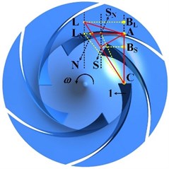
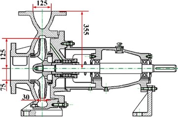
Fig. 2One IS pump with geometrical size
3. Numerical investigations
3.1. Pump geometry with IGV device and mesh generation
The model pump researched in this study is IS150-125-250 and its geometrical size is shown in Fig. 2. At design condition, its flow rate is 200 m3/h, head is 20 m and hydraulic efficiency is 0.95. As shown in Fig. 3, the whole pump with IGV device is presented and the main geometrical size of vane is also given. Gottingen 443 airfoil thickness distribution is used to thicken the vane at both sides symmetrically. The pump consists of three main components: IGV, impeller and volute.
Fig. 3Pump main components
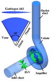
Fig. 4Grid generation
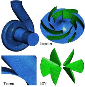
In order to reduce the influence of boundary condition on final solution at inlet and outlet using CFD method, five times of its diameter is extended at IGV inlet and volute outlet. Then the unstructured tetrahedral grid is compelled to all computational domains by Gambit 2.3.16: inlet duct, IGV, impeller, volute and outlet duct as shown in Fig. 4. Also, special care is taken in the near regions of vane surfaces, blade surfaces and volute tongue by the grid refinement technique. Then grid independence has been investigated for reducing computational time and improving reliability of calculation accuracy at the design condition. It reads from Fig. 5 that the pump head and hydraulic efficiency vary slightly when grid number is over 1.60 million. In this article, the mesh scheme of 2.40 million cells is selected to keep balance between calculation time and accuracy order for final solution. Table 1 presents grid number in every component of pump and the total grid can be calculated to be 2,403,189.
Fig. 5Evaluated grid schemes
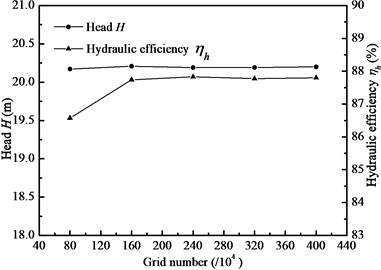
Table 1Grid distribution in each zone
Items | Grid number |
Inlet duct | 702,708 |
Impeller | 851,726 |
Volute | 686,047 |
Outlet duct | 162,708 |
Total | 2,403,189 |
3.2. Governing equations
During numerical simulation, water is selected as working fluid and simulation is performed based on the following assumptions: the process is in steady state for hydraulic performance calculation and in unsteady state for pressure pulsation calculation; the fluid is incompressible; the flow is turbulent; the viscous dissipation is considered. Based on the assumptions above, the basic governing equations [25, 26] are as follows.
Continuity equation:
Momentum equation:
where is Reynolds stress term and in order to solve it, RNG - turbulence model is introduced. The transportation equations of and are given below.
equation:
equation:
The detail explanation of main variables used above will be given at Nomenclature part in alphabetic order of the article.
3.3. Method of solution and boundary condition
The code ANSYS Fluent-16.0 was used to solve pump flow field. RNG - turbulence model and SIMPLEC algorithm were applied to close RANS equations. Velocity inlet was applied for inlet boundary by assuming uniform velocity distribution at inlet cross-section. The turbulent intensity and hydraulic diameter were 3 % and 150 mm respectively. Outflow was used for outlet boundary. The non-slip condition was given at solid walls. Such blade surfaces, hub, and shroud were given as rotational moving wall and others were given as stationary wall. The standard wall function based on the logarithmic law had been used. PRESTO! Scheme was used for pressure term and second order upwind discretization scheme was used for convection terms. The convergence criterion was set as less than 10-4.
For steady conditions, the Multiple Reference Frame (MRF) model was applied to take into account the interaction between stationary volute or IGV and rotating impeller with interface pairs. For unsteady conditions, the Mesh Motion technology was adopted. The steady calculation results were set as initial condition for unsteady calculation. The time step was set 1.15×10⁻⁴ s as the impeller just rotates 1°. It is worth mentioning that all the data used were captured after the centrifugal pump had run stably for 6 cycles.
The test rig has also been built to study the pump performance, as it shown in Fig. 6. It mainly consists of water tank, valves, electromagnetic flow meter, vacuum gauge, pressure gauge, torque meter, centrifugal pump and IGV device. The corresponding instruments are listed in Table 2. Thus, the measurement uncertainty for efficiency is calculated as 0.66 %.
Fig. 6The test rig for hydraulic performance of pump: 1 – motor, 2 – torque meter, 3 – pump, 4 – IGV device, 5 – Vacuum gauge, 6, 7, 10 – valve, 8 – water tank, 9 – water hole, 11 – electromagnetic flow meter, 12 – pressure gauge
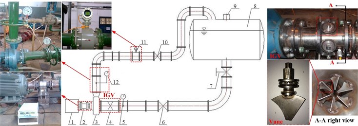
Table 2The instruments with measurement accuracy
Parameters | Type | Range | Accuracy |
Flow rate | LDBE-125SM2C100Z | 0-400 m3/h | 0.5 % |
Inlet static pressure | YB-150A | –0.1-0 MPa | 0.4 % |
Outlet static pressure | YB-150A | 0-0.4 MPa | 0.4 % |
Torque | PTS881 | 0-500 N∙m | 0.1 % |
3.4. Pre-whirl regulation effect for different flow conditions
As shown in Fig. 7, the hydraulic performance comparison of pump between experimental results and numerical data were conducted. Considering the leakage loss and mechanical loss, the numerical efficiency is calculated by empirical formulas [27] based on pump specific speed and they are 0.976 and 0.950 at the design condition, respectively. It can be said from head curves that the numerical head curve is much smoother than the experimental. The numerical head starts lower than the experimental at the low flow conditions and then gets higher at the large flow conditions after 0.9. At the design condition, the numerical head is 20.41 m, the experimental head is 20.00 m and relative error between them is 2.05 %. In addition, from the efficiency curves it can be concluded that the experimental efficiency curve is smoother than the numerical. At the design condition, the numerical efficiency is higher than the experimental by 1.12 %. In general, the tendency of the numerical head and efficiency is in good agreement with the experimental and the relative error between them is within 3 %, which validated the numerical method and the selected models.
Furthermore, by installing IGV device at the inlet of the pump and setting the pre-whirl angle of 15º, the head curve is little lower than that without IGV device, but the efficiency curve is higher than that without IGV device. As a stationary part of the pump, the IGV device brings about extra hydraulic loss and produces a certain positive pre-whirl velocity circulation at 15º pre-whirl angle, and these lead to the head drop. However, the positive pre-whirl velocity circulation could improve flow behavior at the leading region of the impeller and thus improve the efficiency of the pump. Therefore, at proper operating conditions the hydraulic performance of pump can be improved by IGV pre-whirl regulation. This is rightly echoing the description in part 2.
Fig. 7Performance comparisons between experimental result and numerical data
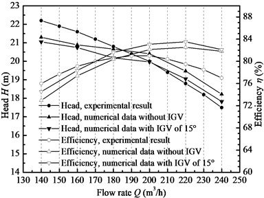
Fig. 8Pre-whirl regulation effect under three typical flow conditions
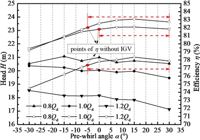
Fig. 93D streamlines through IGV device to impeller
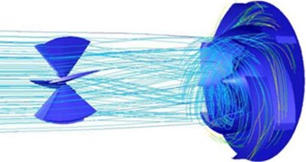
Fig. 8 illustrates pre-whirl regulation effect along with pre-whirl angles. Under three typical flow rate conditions and aided by IGV device, the head does not change very much, but the efficiency grows gradually and reaches the peak at pre-whirl angle of 15º. The red point marks in the figure represent the performance without IGV. The efficiency is improved at pre-whirl angle being from –5º to 30º. It seems that pre-whirl regulation under positive pre-whirl angle is effective under different flow conditions and it is believed to have to do with inlet setting angle of impeller blade. But this does not matter to the discussion on the effect of vane number of IGV on pump performance, thus the next work will be conducted on the pre-whirl angle of 15 º under different flow conditions. 3D streamlines from IGV to impeller are shown in Fig. 9. It can be seen obviously that the fluid after IGV has been swirled with some extent of velocity circulation, and thus it could improve flow pattern before impeller to get good adaption of no-incidence condition. As a consequence, incidence loss at leading region is reduced as well as back flow loss at flow passage and eventually enlarge high efficiency operation range.
4. Influence of vane number on pump hydraulic performance
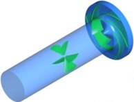
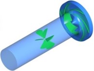
The influence of vane number of IGV device on pump performance is firstly investigated. Four sets of IGV devices with 5, 6, 7 and 9 vanes are generated to assemble with the centrifugal pump shown in Fig. 10. As the description before, the pre-whirl angle is set of 15º and the hydraulic performance curves is obtained at six flow conditions from 0.7 to 1.2.
Fig. 11 shows the hydraulic performance of the pump installed by the four sets of IGV devices. Overall, at the positive pre-whirl regulation conditions, no matter what the vane number is, the head curves are lower compared with that without IGV device. The efficiency of the pump with different vane numbers is higher than that without IGV device. But the variation tendency is different between them with the increasing of vane number. As for the head performance and with the increasing of vane number, the head difference is quite small for 5, 6 and 9 vanes. Among them, the head for 6 vanes is higher than the others and that for 7 vanes is the lowest. The head tendency with vane number is very complex. Compared with the head and efficiency curves without IGV devices, the hydraulic curves for different vane numbers perform the similar shape and become stable as well.
Fig. 10Geometry of IGV with different vanes being 5, 6, 7 and 9
a) 5 Vanes
b) 6 Vanes

c) 7 Vanes

d) 9 Vanes
Fig. 11Pump hydraulic performance curves under various vanes of IGV
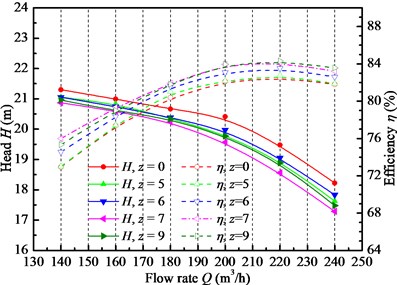
In addition, as for the efficiency performance, with the increasing of vane number, the efficiency gradually grows. The efficiencies for 7 and 9 vanes are the highest and the difference between them is tiny. Thus, it deduces that further increasing vane number will benefit very little on pump efficiency improvement. Here one point is worth to note that the heads for 7 and 9 vane are lower than that for 6 vanes, but the efficiency is opposite. Therefore, whether the IGV device can improve the pump hydraulic performance is like two-strength conflict, which can be regarded as a game. One is the hydraulic loss brought by IGV device itself as one stationary component for the pump and the other is the benefit from the hydraulic performance improvement by changing flow patter to better adapt no incidence condition at the leading region of the impeller as well as the flow channel. At the design condition, the efficiency for 7 and 9 vanes are increased by 1.81 % and 1.83 %, respectively.
In short, vane number of IGV device is one important factor influencing the pump hydraulic performance, but the effects on head and efficiency are different. The IGV device of 6 vanes can produce higher head and that of 7 or 9 vanes can bring about higher efficiency. Thus, the vane number of IGV device being 6 or 9 is acceptable and can improve pump hydraulic efficiency.
5. Analysis of pressure pulsation in centrifugal pump with various vane numbers
The investigation above showed that vane number of IGV device is an important parameter influencing pump hydraulic performance. However, the effect of vane number on hydraulic stability is seldom studied. Thus, in this study, the pressure pulsation is investigated to obtain the effect of vane number on pump stabilization. As shown in Fig. 12, the monitoring points are presented. At the interface of impeller and volute, the monitoring points are set every 45º at the mid-span section of impeller, i.e., -. Three extra points are set at the close region to volute tongue, i.e., -, and point is the closest one to tongue. Then the pressure pulsation characteristics are conducted on these points from views of time domain and frequency domain. Time domain analysis can give a direct-viewing impression for readers while frequency domain analysis can be used to judge causes of pressure pulsation by observing power spectral density magnitude and domain frequency.
Fig. 12Monitoring points of pressure around impeller outlet
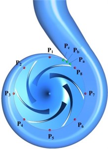
Fig. 13Dimensionless pressure pulsation amplitude at point Pb
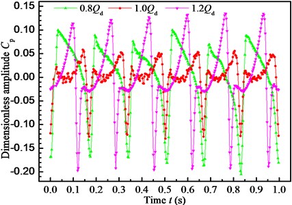
To evaluate pressure pulsation characteristics, the pressure pulsation amplitude meaning the peak to peak value is defined as the maximal transient pressure difference within one rotating period of impeller. The dimensionless pressure coefficient is also defined as follows:
where is the difference between transient pressure and the average pressure within one rotating period, is fluid density, and is tip velocity of impeller.
5.1. Time domain characteristics analysis of pressure pulsation
For a centrifugal pump and due to relatively asymmetrical position of impeller blade and volute tongue, blade passing frequency (BPF) has a significant effect on pressure pulsation characteristic [28]. As shown in Fig. 13, the dimensionless pressure amplitude at point is monitoring within one rotating period. It is observed clearly that one complete period contains six peaks and six troughs due to the interaction effect between the rotating impeller and the stationary volute tongue, and six blades of impeller lead to six pressure extreme points. In order to make a comparative analysis of flow rate on pressure pulsation, three typical flow conditions, i.e., 0.8, 1.0 and 1.2, are selected to study. Generally, the effect of flow rate on pressure pulsation is similar in shape, but the variation tendency is different. The pressure for 0.8 is always earlier than the other two reaching the peak value. Moreover, the peak to peak value for 0.8 and 1.2 is almost in the same level and quite larger than that for 1.0. Compared with the design condition, the peak to peak value for 0.8 and 1.2 is increased by 62.34 % and 76.70 %, respectively. Thus, the pump is stable at the design condition due to the rotor-stator interaction and it should avoid working at off-conditions.
In order to clearly observe the flow feature along the spiral channel, 11 points are set to record the static pressure at the mid-span section of the volute. The time domain characteristic is carried out for six flow conditions. As shown in Fig. 14, the pressure changes very similarly for the six flow conditions, that is, the pressure is high at close to tongue region and it decreases at far-off tongue region. Clearly, the pressure pulsation amplitude at point is the highest among all monitoring points. The pressure at point is almost 2.23 times of the average level for point from to . Thus, it can be concluded that the asymmetrical volute tongue enhances the strength of pressure pulsation and it is the volute tongue inducing the hydraulic instability in terms of pressure pulsation. In addition, it also can be observed that the pressure at 1.0 is the lowest and that at 0.7 and 1.2 is the largest. The pressure decreases as the flow rate increases, dropping to the lowest at 1.0 and then growing at larger flow conditions. The pressure at point for 0.7 and 1.2 is 2.36 and 2.29 times of that for 1.0, respectively. Thus, the pump working at the design condition is more stable and should avoid running at off-conditions.
Fig. 14Pressure pulsation amplitude at all points under different flow rates
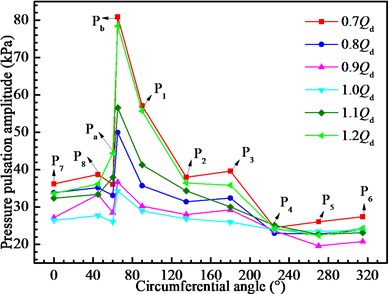
Fig. 15Pressure pulsation amplitudes at point Pb for different guide vane numbers
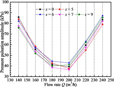
As studied above, volute tongue has great importance to pressure pulsation characteristic and due to rotor-stator interaction, the pressure at point is more obvious. Hence in the next work, the point is taken as the unique monitoring point to study the effect of vane number of IGV device such as 0, 5, 6, 7 and 9 on pressure pulsation characteristic. Pressure pulsation amplitudes at monitor point with different vane numbers and different flow rate conditions are shown in Fig. 15. In general, the pressure amplitude decreases as the flow rate increases, dropping to the lowest at 0.9 and 1.0 and then growing to the larger flow conditions, which is like a parabola style, U-type for all vane numbers. As shown in the Fig. 15, the pressure pulsation amplitude can be decreased by some extent by changing vane number of IGV device, but the effect is limited. The pressure pulsation amplitude for different vane numbers shows great difference. At the large flow conditions, the pump installed with 5 or 7 vanes IGV device shows better pressure pulsation characteristic than the others. But at the small flow conditions, the IGV device with 7 or 9 vanes can help the pump achieve better pressure pulsation characteristic for the lower pressure pulsation amplitude. Compared with the pump without IGV device, the pump installed 6 vanes IGV device gets higher pressure under almost all flow conditions and would worsen the pump stability. This may be caused by the fact that the IGV device has the same number of vanes to impeller blades [19]. Therefore, as for the time domain analysis for pressure pulsation, the vane number of IGV device indeed can improve pump hydraulic stability but the effect is complex. Overall, 7 vanes IGV device can improve pump pressure pulsation characteristic and realize better hydraulic stability.
5.2. Frequency domain characteristics analysis of pressure pulsation
Besides the time domain analysis for pressure pulsation, the frequency domain characteristic is also important to evaluate pulsation. By Fast Fourier Transform (FFT), the pressure pulsation in time domain could be transformed into frequency domain and then frequency domain analysis can be conducted. The power spectral density or power spectrum, power distribution along with frequency, is chosen to describe amplitude value of pressure pulsation.
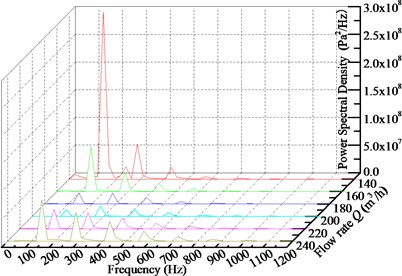
The frequency domain analysis of pressure pulsation for pump without IGV device is firstly carried out under different flow conditions. Fig. 16 shows the frequency domain characteristics of pressure pulsation for six flow rate conditions. It reads that the frequency domain characteristic for each flow rate condition shows discrete spectral characteristics and the main frequencies are blade passing frequency (BPF, 145 Hz) and its multiples. There appears broadband characteristic in the frequency spectrum at almost all flow rate conditions except 0.7. At 0.7, the main frequency characteristic (BPF) is more obvious. In addition, the flow rate also affects pressure pulsation characteristic very much. With the increasing of flow rate, the power spectral density at BPF decreases first, drops to the lowest at the design condition and then grows to the large flow rate conditions. More deviation from the design flow rate results in larger difference on power spectral density. The power spectral density at the dominant frequency under flow rate of 0.7 is the maximum being 2.83×10⁸Pa2/Hz among all flow conditions and it is 6.96×10⁷Pa2/Hz under 1.2, which is about 24.83 and 6.12 times of that for the design condition. Therefore, it can be concluded that the pump is more unstable for small flow conditions than that for large flow conditions. The pump should avoid working at small flow conditions.
Fig. 16Frequency domain characteristics of pressure pulsation for pump without IGV device at monitoring point Pb under different flow conditions
After analyzing the pressure pulsation characteristic in frequency domain of the pump without IGV device, the frequency domain analysis for the pump with different sets of IGV device is conducted as follows. As shown in Fig. 17, the pressure pulsation characteristics of various vane numbers after FFT are presented. And in Table 3 the power spectral density at the dominant frequency is summarized as a supplementary explanation.
Generally, for each flow rate condition, the introduction of IGV device with different number of vanes does not change the wave shape of frequency domain characteristics compared with the pump without IGV device. The spectrum band is almost the same. The main frequencies are still BPF and its multiples. The discrete spectral characteristic is also observed. And with the increasing of vane number, the amplitude-frequency characteristic of pressure pulsation is also complex. Considering that the pump itself without IGV device has relatively stable pressure pulsation characteristics, the variation of pressure pulsation by changing vane number may not be displayed on power spectral density. Among all the vane numbers from 5 to 9, 5 and 6 vanes IGV device can achieve better pressure pulsation, but the improved effect is very limited.
Fig. 17Frequency domain characteristics of pressure pulsation for pump installed IGV device with various numbers of vane at monitoring point Pb under different flow conditions
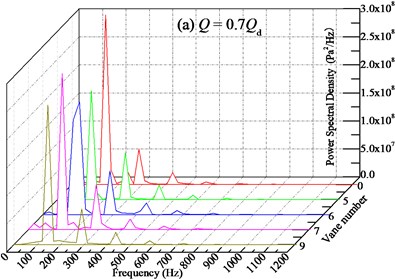
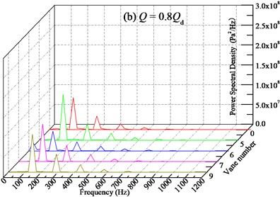
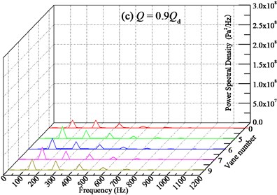
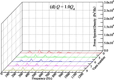
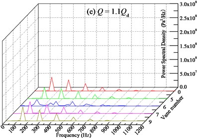
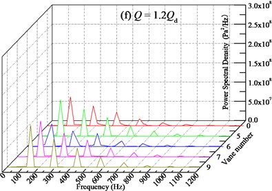
In addition, from Table 3 it can be seen that with the increasing of vane number, the power spectral density at the BPF is distributed different. Overall, the IGV device with 6 vanes can remarkably decrease the power spectral density at all flow rate conditions, and compared with the pump without IGV device, it could decrease maximally by 35.58 % at 1.2 with average level about 17.81 %. This may owe to resonance caused by the same number of IGV vane and impeller blade. What’s more, the pump installed with 6 vanes of IGV device is not found to have high frequency of pressure pulsation. It is worth to note that when the flow rate is far-off the design condition, such as 0.7, the IGV with various vanes all can decreases the power spectral density. The closer of the flow rate to the design condition, the weaker of the decreasing ability. Meanwhile, as for the IGV device with 9 vanes, the relatively high power spectral density at the BPF is observed at all flow conditions. Therefore, considering the stable operation at off-conditions for the pump with different vanes of IGV device, the frequency domain characteristic of pressure pulsation for pump with 6 vanes is better and the vane number should be selected as 6 for engineering application.
Table 3Power spectral density at the dominant frequency of point Pb with various vane numbers for different flow conditions (/107, unit: Pa2/Hz)
Flow rates | Vane number | ||||
0 | 5 | 6 | 7 | 9 | |
0.7 | 28.27 | 19.35 | 18.73 | 27.50 | 24.76 |
0.8 | 7.53 | 11.47 | 4.94 | 9.50 | 9.48 |
0.9 | 1.89 | 3.10 | 2.70 | 3.15 | 2.85 |
1.0 | 1.14 | 1.04 | 0.95 | 1.20 | 1.22 |
1.1 | 3.26 | 3.97 | 2.10 | 4.21 | 5.02 |
1.2 | 6.96 | 9.36 | 4.92 | 9.26 | 10.86 |
As a whole, the pre-whirl regulation is a feasible way to regulate pump hydraulic performance, especially at off-conditions. The vane number is one important parameter for the IGV device and need to be considered carefully. Just like a game, the vane number cannot be determined individually either on hydraulic performance or the pressure pulsation characteristic of the pump. It depends on the detail engineering application background. As the description above, the IGV device of 6 vanes can produce higher head and that of 7 or 9 vanes can bring about higher efficiency. And the IGV device with 6 vanes can remarkably decrease the power spectral density at all flow rate conditions from the view of time domain analysis. However, from the perspective of frequency domain analysis 7 vanes IGV device can improve pump pressure pulsation characteristics and realize better hydraulic stability. Therefore, it is hard to determine the best vane number, but the vane number in this study is suggested to be 6 for better hydraulic performance.
6. Conclusions
In this study, the effects of vane number on hydraulic performance and pressure pulsation are considered based on one IS150-125-250 centrifugal pump. Then the three-dimensional unsteady flow fields are conducted by Fluent-16.0. The accuracy of numerical results has been validated by the experiment. Some conclusions can be summarized as follows.
1) The mechanism of pre-whirl regulation for off-condition is explained by velocity triangle and it is anticipated to get no-incidence flow pattern at the leading of impeller.
2) Vane number is an important factor influencing the pump performance, but the effects on head and efficiency are different. 6 vanes IGV device can produce higher head and 7 or 9 vanes IGV device can bring about higher efficiency.
3) The vane number of IGV device indeed can improve hydraulic stability from time domain analysis, but the effect is complex. 7 vanes IGV device can improve pump pressure pulsation characteristic and realize better hydraulic stability.
4) 6 vanes IGV device can remarkably decrease the power spectral density and compared with the pump without IGV device, it could decrease maximally by 35.58 % at 1.2 with average level about 17.81 %.
5) It is hard to determine the best vane number to obtain both the hydraulic performance and pressure pulsation characteristics, but 6 vanes of IGV device is suggested for engineering application to obtain better hydraulic performance in this study.
References
-
Yuan Jianping, Zhang Gaicheng, Chen Xiang Operation adjusting methods for energy consumption of centrifugal pump. Drainage and Irrigation Machinery, Vol. 24, 2006, p. 44-47, (in Chinese).
-
Cui M. M. Unsteady flow around suction elbow and inlet guide vanes in a centrifugal compressor. ASME Turbo Expo 2004: Power for Land, Sea, and Air, American Society of Mechanical Engineers, 2004, p. 717-735.
-
Xiao Jun, Gu Chuangang, Shu Xinwei, et al. Performance analysis of a centrifugal compressor with adjustable inlet guide vanes. Journal of Power Engineering, Vol. 26, Issue 6, 2006, p. 804-807, (in Chinese).
-
Fukutomi J., Nakamura R. Performance and internal flow of cross-flow fan with inlet guide vane. JSME International Journal Series B Fluids and Thermal Engineering, Vol. 48, Issue 4, 2005, p. 763-769.
-
Bailie S. T., Ng W. F., Copenhaver W. W. Experimental reduction of transonic fan forced response by IGV flow control. ASME Turbo Expo 2004: Power for Land, Sea, and Air, American Society of Mechanical Engineers, 2004, p. 527-537.
-
Kim Y. T., Nam S. H., Cho Y. J., et al. Tubular-type hydro-turbine performance for variable guide vane opening by CFD. New Trends in Fluid Mechanics Research, Springer Berlin Heidelberg, 2007, p. 424-427.
-
Gui Shaobo, Cao Shuliang, Tan Lei, et al. Numerical simulation and experiment of inlet guide vane pre-whirl regulation for centrifugal pump. Transactions of the Chinese Society for Agricultural Machinery, 2009, (in Chinese).
-
Cao Shuliang, Tan Lei, Gui Shaobo Design and experiment of inlet guide vane for centrifugal pump. Transactions of the Chinese Society for Agricultural Machinery, Vol. 41, Issue 9, 2010, p. 31-35, (in Chinese).
-
Zhou C. M., Wang H. M., Huang X., et al. Influence of the positive pre-whirl on the performance of centrifugal pumps with different airfoils. IOP Conference Series: Earth and Environmental Science, IOP Publishing, Vol. 15, Issue 3, 2012, p. 032020.
-
Tan L., Cao S. L., Gui S. B. Hydraulic design and pre-whirl regulation law of inlet guide vane for centrifugal pump. Science China Technological Sciences, Vol. 53, Issue 8, 2010, p. 2142-2151.
-
Tan L., Cao S. L., Wang Y. M., et al. Influence of axial distance on pre-whirl regulation by the inlet guide vanes for a centrifugal pump. Science China Technological Sciences, Vol. 55, Issue 4, 2012, p. 1037-1043.
-
Tan L., Cao S., Gui S., et al. Experiment and numerical simulation of cavitation performance for centrifugal pump with inlet guide vane. Jixie Gongcheng Xuebao (Chinese Journal of Mechanical Engineering), Vol. 46, Issue 18, 2010, p. 177-182, (in Chinese).
-
Tan L., Zhu B., Cao S., et al. Influence of pre-whirl regulation by inlet guide vanes on cavitation performance of a centrifugal pump. Energies, Vol. 7, Issue 2, 2014, p. 1050-1065.
-
Yongxue Z., Pengfei S., Cong X., et al. Experimental and numerical investigations of cavitation in a centrifugal pump with pre-whirl regulation. Transactions of the Chinese Society for Agricultural Machinery, 2014, (in Chinese).
-
Khalifa A. E., Al-Qutub A. M., Ben-Mansour R. Study of pressure fluctuations and induced vibration at blade-passing frequencies of a double volute pump. Arabian Journal for Science and Engineering, Vol. 36, Issue 7, 2011, p. 1333-1345.
-
Wang H., Tsukamoto H. Fundamental analysis on rotor-stator interaction in a diffuser pump by vortex method. Journal of Fluids Engineering, Vol. 123, Issue 4, 2001, p. 737-747.
-
Wang H., Tsukamoto H. Experimental and numerical study of unsteady flow in a diffuser pump at off-design conditions. Journal of Fluids Engineering, Vol. 125, Issue 5, 2003, p. 767-778.
-
Xu Z. H. The Analysis of Three-Dimensional Flow in High-Speed Pump and Research of Its Fluid-Induced Pressure Fluctuation. Tsinghua University, Beijing, 2004.
-
Zhang M., Tsukamoto H. Unsteady hydrodynamic forces due to rotor-stator interaction on a diffuser pump with identical number of vanes on the impeller and diffuser. Journal of Fluids Engineering, Vol. 127, Issue 4, 2005, p. 743-751.
-
Ma X., Li X., Wang N., et al. Effect of number of guide pulley vane on performance of gas-liquid mix-transporting pump. Journal of Lanzhou University of Technology, 2012.
-
Desheng Z., Weidong S., Chuan W., et al. Influence of impeller and guide vane blade number on pressure fluctuation in mixed-flow pump. Journal of Drainage and Irrigation Machinery Engineering, 2012, (in Chinese).
-
Hou Hucan, Zhang Yongxue, Li Zhenlin, et al. Optimization design of inlet guide vane in a centrifugal pump based on orthogonal method. Journal of Engineering Thermophysics, Vol. 36, 2015, p. 2618-2624, (in Chinese).
-
Hou H., Zhang Y., Li Z., et al. Hydraulic design of inlet guide vane and its full flow passage numerical simulation on centrifugal pump. International Mechanical Engineering Congress and Exposition, American Society of Mechanical Engineers, 2014.
-
Zhang Y., Zhang Y., Zhang J., et al. Study on pressure pulsation in the volute of a centrifugal pump by large eddy simulation. International Mechanical Engineering Congress and Exposition, American Society of Mechanical Engineers, 2014.
-
Ng E. Y. K., Tan S. T. Comparison of various turbulence models in rotating machinery blade-to-blade passages. International Journal of Rotating Machinery, Vol. 6, Issue 5, 2000, p. 375-382.
-
Wang Fujun Computational Fluid Dynamics Analysis: Principle and Application of CFD Software. Tsinghua University Press Co., Ltd., 2004, (in Chinese).
-
Zhang J., Xu C., Zhang Y., et al. Quasi-3D hydraulic design in the application of an LNG cryogenic submerged pump. Journal of Natural Gas Science and Engineering, Vol. 29, 2016, p. 89-100.
-
Si Q., Yuan J., Yuan S., et al. Numerical investigation of pressure fluctuation in centrifugal pump volute based on SAS model and experimental validation. Advances in Mechanical Engineering, Vol. 6, 2014, p. 972081.
Cited by
About this article
This research was supported by Science Foundation of China University of Petroleum, Beijing (No. 2462015YQ0411).
