Abstract
A preliminary approach to calculate hydromount elastic shell dynamic stiffness using finite difference method is presented in the article. This approach is necessary to calculate and assess maximum shear deformations of hydromount rubber shell needed to further determine the hydromount stiffness and damping coefficients at resonance frequencies. For this reason, finite difference method is applied when assessing maximum shear deformations of hydromount rubber shell, caused by variable loads. It was found that using reduced length and reduced arc dimensions of cut-out hydromount shell segment the equivalent stiffness can be determined. The novelty of the proposed method lies in the possibility of a quick and fairly accurate numerical calculation of the rubber shell stiffness using the values of the rubber modulus of elasticity, its permissible shear stress, and the nominal load (weight). This approach can be used to determine and optimize the geometric dimensions of the mounts shells with a given stiffness.
Highlights
- Proposed method for calculating the stiffness coefficient of the hydromount elastic shell is based on the finite differences method.
- The method is available for a quick calculation of the stiffness for known geometric parameters of the shell as well as for optimizing the shape of the shell at known dynamic loads acting on the hydromount.
- The method consists in dividing the elastic shell into single elements interacting with each other, as elements of an equivalent reduced bar.
- Comparison of the results of numerical and experimental investigations showed that the proposed method for calculating stiffness has good accuracy (relative error about 2.5%).
1. Introduction
There are certain limitations, unfortunately, with respect to developing vibration insulation of traditional vibration isolators, hydromounts falling into this category as well. These limitations are general and are due with impossibility of lowering the mount stiffness coefficient beyond a certain level. Thus, traditional vibration insulation comprises elastic elements between vibration source and the protected object. These elements are made of rubber, metal and composite materials, and they transfer the object weight, operating and emergency loads onto the protected object along with vibration insulation itself [1-3].
General properties of vibration isolators, hydromounts falling into this category as well, can be presented by three time-independent parameters: stiffness, viscosity, and inertia (mass). Main bearing element of the hydromount is an elastic block – a rubber shell, placed between the steel frame and the plate of mount [3-5].
In low frequency range it is admissible to consider only static stiffness of hydromount, because the rubber shell deformation rate and especially acceleration rate are low. On the other hand, hydromount stiffness is definitely fraught with viscous losses [4-5].
Consequently, for forecasting traditional hydromounts it is necessary to consider only one parameter – their stiffness [3]. Structural dimensions of hydromount determine the rubber shell stiffness and damping properties.
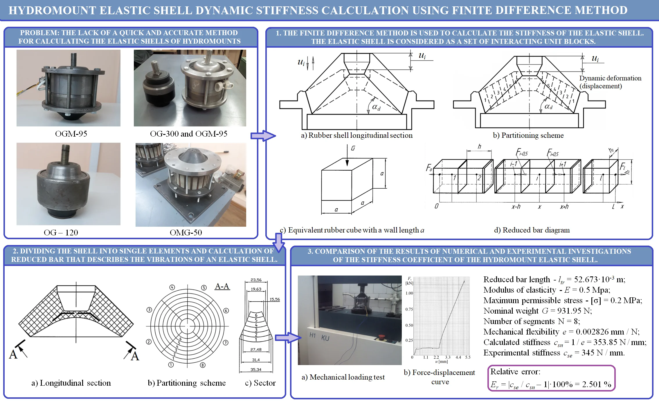
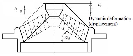
Fig. 1(a) shows deformation pattern of the hydromount rubber bearing element.
Hydromount static stiffness coefficient cs is calculated basing on the rubber block geometrical dimensions. Stiffness of the membrane can be disregarded when it is far less than the rubber shell stiffness [6]. Rubber block deformation causes hydromount’s internal enclosed volume change, and the working fluid is bound to thrust apart the rubber shell, acting on its internal surface. At this, internal pressure of the working fluid filling the hydromount increases.
Fig. 1Deformation pattern of the hydromount rubber bearing element (α – dynamic angle)
a) Rubber shell longitudinal section
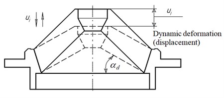
b) Equivalent rubber cube with a wall length а
In order to determine hydromount parameters it is necessary to know static load characteristics and the vibration source dynamic characteristics. Normally, the object’s mass characteristics are stated in its technical passport while the power unit’s vertical oscillations eigenfrequency is set within the range of 8 ÷ 10 Hz [3, 6-8]. Basing on this parameter the necessary dynamic stiffness at low frequency range can be determined (lower than ):
where – the object’s weight per mount, kg; – eigenfrequency, Hz.
Assume that driven oscillation frequency is constant, and it satisfies the inequality: ( – circular frequency, rad/s).
The hydromount low stiffness is an efficient vibration insulation condition [9]. The first obstacle in lowering stiffness is the hydromount’s dimensions growth. According to linear elasticity theory when considering hydromount rubber shell complex stress state it is possible to substitute it for simple stress state of stretching or compression [2, 9]. Represent the rubber shell as a cube with a wall lenght (Fig. 1(b)).
Under the weight of such rubber shell load, stiffness condition must be fulfilled at compression or any other type of deformation. Hooke’s law being observed – minimal rubber cube dynamic stiffness is obtained equal to its static stiffness in the form of [2, 9]:
where – rubber cube stiffness, N/m; – elasticity modulus, МPа; – vibration source weight, N, – gravity acceleration; [] – rubber shell admissible stress, Pa; – wall length, m.
Rubber shell admissible stress is found from Eq. (2):
The first eigenfrequency of hydromount rubber cube-shaped shell is equal to:
In order to enhance vibration insulation quality eigenfrequency should be possibly detuned from frequencies of driven oscillations. Hydromount rubber shell quality characteristic in its simplest form is vibration insulation coefficient [2-3]:
where – circular frequency of driven oscillations, rad/s.
Expressing vibration insulation coefficient through hydromount rubber cube-shaped shell dimension and rubber constant the following dependence is obtained [9]:
Hydromount rubber shell efficiency is determined by vibration insulation coefficient within geometric frequency range 2-63 Hz and is set by the design engineer. In any case vibration insulation coefficient should be considerably less than 1. Corresponding hydromount rubber shell static sagging is found by the formula [9]:
where – on-load hydromount rubber shell sagging.
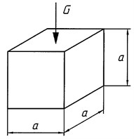
The proposed expression Eq. (2) and the pattern (Fig. 1(b)) cannot be applied to calculate real rubber shell stiffness, because of that there are do not consider shell generatrix tilting angle to the plane which is normal to the hydromount axis. Thus, in studies [3, 8] in order to determine rubber shell stiffness a formula was proposed, obtained as a result of experimental tests:
where – nominal static load, kg; – shell elasticity, mm; – midsection shell generatrix length, cm; – rubber mix hardness in Shore units; – shell thickness in the generatrix mid, cm; 33° – tilting angle of the shell; – mounting plate diameter, cm; = 10 – coefficient.
Hydromount rubber shell stiffness calculation error using Eq. (8) and diagram (Fig. 2(a)) for different hydromount design variants was 9 to 14 %. Nevertheless, a more accurate rubber shell stiffness calculation is necessary. Such calculation is based on finite difference method (FDM) [2] allowing to carry out a detailed analysis of on-load rubber shell behaviour. This method comprises rubber shell stress and strain calculation considering rubber low compressibility factor.
Fig. 2Diagram to determine shell stiffness: 1 – body; 2 – shell; 3 – mounting plate
a) Rubber shell dimensions
b) Partitioning scheme
2. Hydromount elastic shell longitudinal oscillations
Using FDM [10, 11] let’s visualize rubber shell longitudinal section (Fig. 2(b)). On the hydromount rubber shell cross-section surface match marks are made at pitch [2], dividing the shell into six length elements. The match marks made at pitch divide shell generatrix length into six length intervals.
If the hydromount mounting plate executes mechanical oscillations directionally angle wise to hydromount axis , the shell sections are displaced parallely to each other directionally angle wise to hydromount axis . Herewith, distances between the match marks do not remain constant and equal to , but also change. At some spots match marks crowd together while at other – become less dense. Elastic longitudinal oscillations emanate rubber shell lengthwise from the mounting plate atop to the block base from the bottom and vice versa [2, 10, 12].
When the hydromount mounting plate is stopped oscillating process in the rubber shell gradually subsides. In the end, all match marks return to the initial state, i.e., state of equilibrium. This represents one of the pictures of elastic rubber shell longitudinal oscillations. It is noteworthy that at any longitudinal oscillations the shell elements cross-sections remain flat and parallel to each other angle wise to hydromount axis . Thus, all the shell points displacements depend only on one coordinate directionally angle wise to hydromount axis [2, 12].
When the elastic shell elements are moving, all the shell elements are considered to be in dynamic equilibrium state at any time. However, to calculate the shell elementary motion, it is necessary to divide the shell into sectors and reduce the sectors to rectangular cross-section bars.
3. Reducing the shell sectors to rectangular cross-section bars of equivalent stiffness
Let’s divide the rubber shell into eight sectors – segments (Fig. 3) and conventionally cut out one rubber segment out of the shell [10, 11]. External and internal surfaces of the segments, conventionally cut out of the rubber shell, have truncated triangle surface configuration, which considerably complicates the task of determining rubber shell stiffness numerical value [3].
Fig. 3Hydromount rubber shell division
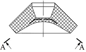
a) Longitudinal section
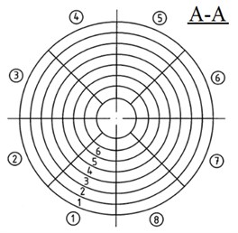
b) Partitioning scheme
c) Sector
The reduced bar total length will also change. Segment arcs length of the reduced bar remain constant along the bar full length. and reduced bar length – are the basic reduced bar geometrical dimensions to determine stiffness value of the segment of the rubber shell [13]:
where and – dimensions of arcs length and segment elements length.
To determine the reduced bar length let’s consider shell segment, operating on compression (Fig. 3(c)). The cut-out shell segment can be viewed as connected in series discrete elements of the hydromount elastic shell with corresponding chord dimensions and lengths [13]. In order to determine the reduced rectangular bar length, we use the formula:
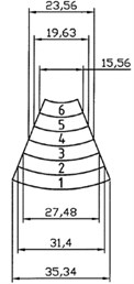
To determine and of external and internal surface elements of hydromount shell rubber segment (Fig. 3) we have to use Eq. (9) and Eq. (10). Dimensions of external surface of shell segment are equal to: 35.34 mm, 31.40 mm, 27.48 mm, 23,56 mm, 19.63 mm, 15.56 mm; 7 mm, 7 mm, 7 mm, 7 mm, 7 mm, 7 mm.
Reduced arc length of cut-out segment external surface of rubber shell is calculated by Eq. (9) and equal to 26.495 mm. Reduced length of cut-out segment external surface of rubber shell is calculated by Eq. (10) and equal to 45.361 mm.
Geometrical dimensions of internal surface of cut-out rubber shell segment are equal to: 28.27 mm, 23.56 mm, 18.84 mm, 14.13 mm, 9.42 mm, 4.72 mm; 7 mm, 7 mm, 7 mm, 7 mm, 7 mm, 7 mm.
Reduced arc length of cut-out segment internal surface of rubber shell is calculated by Eq. (9) and equal to 16.490 mm. Reduced length of cut-out segment internal surface of rubber shell is calculated by Eq. (10) and equal to 59.986 mm.
Any element length of cut-out rubber shell segment is accepted as reduced arc length of elements of external and internal trapezoidal segment surfaces which simplifies calculation of trapezoidal segment reduced length. Length mean value of trapezoidal segment is found by trapezoid midline 52.673 mm [13].
Conventionally cut out segment flexibility is determined as follows [14]:
where – stiffness of each section of shell segment, determined by Eq. (2), 1…6, .
By substituting stiffness of each section of shell segment in Eq. (11) expression of hydromount rubber shell segment flexibility (pliability) is obtained [13-14]:
4. Analysis of the results
To the accuracy estimation of the proposed method one can compare the results of numerical calculations with the experimental static loading results presented in [15]. The photographs of the hydromount prototype and its loading process as well as the resulting force-displacement curve are shown in Fig. 4.
From the linear section of the ‘force-displacement’ characteristic it follows that the hydromount shell stiffness is 345 N/mm. Substituting in Eq. (12) the values 52.673·10-3 m, as well as the modulus of elasticity of industrial rubber 4 MPa [16], maximum permissible stress of industrial rubber 20 N/cm2 = 0.2 MPa [16], nominal weight 95·9.81 = 931.95 N, we obtain the value of mechanical flexibility 0.002826 mm/N. Therefore, the stiffness of the shell 1 / e = 353.85 mm/N.
Dividing the experimental stiffness value by the one obtained as a result of the numerical calculation , we can determine the relative error characterizing the accuracy of the method: ·100 % = 2.501 %.
Comparison of the hydromount mechanical loading results with the results of numerical calculations made it possible to conclude that the proposed method for numerically calculating of the hydromounts stiffness coefficient has a sufficiently high accuracy and is recommended for determining the geometric dimensions of their rubber shells.
Fig. 4Testing of magnetorheological hydromount with rubber shell
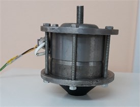
a) Prototype
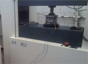
b) Mechanical loading test
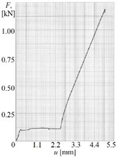
c) Force-displacement curve
5. Conclusions
In summary, using reduced length and reduced arc dimension of cut-out hydromount shell segment, reduced to elastic bar of equivalent stiffness, calculation of hydromount shell parameters can be significantly simplified. The reduced dimensions of elastic bar of equivalent stiffness having been determined, maximum shear strain and stress in the reduced elastic bar are assessed using finite difference method based on method of sections. This method can be used to determine the geometric dimensions of the hydromount shells with a given stiffness.
References
-
K. F. Frolov and V. V. Bolotin, Vibrations in Engineering. Vol 1., (in Russian), Moscow: Mashinostroenie, 1978.
-
Е. N. Makvetsov and A. M. Tartakovsky, Mechanical Impact and Radio Electronic Equipment Protection. (in Russian), Мoscow: Radio and communication, 1993.
-
B. А. Gordeev, V. I. Erofeev, A. V. Sinev, and О. О. Mugin, Vibration Protection Systems Using Rheological Media Inertia and Dissipation. (in Russian), Moscow: FizMatLit, 2004.
-
S.-B. Choi, S.-R. Hong, K.-G. Sung, and J.-W. Sohn, “Optimal control of structural vibrations using a mixed-mode magnetorheological fluid mount,” International Journal of Mechanical Sciences, Vol. 50, No. 3, pp. 559–568, Mar. 2008, https://doi.org/10.1016/j.ijmecsci.2007.08.001
-
M. Brigley, Y.-T. Choi, N. M. Wereley, and S.-B. Choi, “Magnetorheological isolators using multiple fluid modes,” Journal of Intelligent Material Systems and Structures, Vol. 18, No. 12, pp. 1143–1148, Dec. 2007, https://doi.org/10.1177/1045389x07083129
-
S. N. Okhulkov, А. S. Plekhov, D. Y. Titov, and Y. V. Shevirev, Methods and Devices of Electromechanical Complexes Vibrations Reduction. (in Russian), Nizhny Novgorod: NNSTU n.a. R.E. Alekseev, 2016.
-
B. А. Gordeev, V. I. Erofeev, and А. S. Plekhov, Math Models of Adaptive Vibration Isolators of Mobile and Stationary Objects. (in Russian), N. Novgorod: NNSTU n.a. R.E. Alekseev, 2017.
-
F. V. Lozhkin, “Hydromounts research for vehicle vibration protection,” (in Russian), Ph.D. Thesis, Nizhny Novgorod, 2002.
-
S. P. Timoshenko, Oscillations in Engineering. (in Russian), Moscow: Nauka, 1967.
-
A. Iserles, A First Course in the Numerical Analysis of Differential Equations. Cambridge: Cambridge University Press, 2008, https://doi.org/10.1017/cbo9780511995569
-
J. D. Hoffman and S. Frankel, Numerical Methods for Engineers and Scientists. Boca Raton: CRC Press, 2001.
-
B. А. Gordeev, S. N. Okhulkov, А. N. Osmekhin, and А. Е. Shokhin, “Reducing vibration overloads excited by rotary shafts in transient modes,” Russian Engineering Research, Vol. 2, pp. 9–15, 2018.
-
T. I. Omarov, L. V. Konchina, I. А. Goncharova, and А. Т. Shampieva, “Reduced torsional stiffness of rail-tracked machine drive transmission shafts,” Electric Power Industry, Information Technology, Innovations, Smolensk, pp. 227–232, 2014.
-
Y. Lei, D. Wang, Z. Liu, and X. Yang, “A new model for calculating time-varying gearmesh stiffness,” Vibroengineering Procedia, Vol. 14, pp. 334–339, Oct. 2017, https://doi.org/10.21595/vp.2017.19139
-
B. Gordeev, S. Okhulkov, and A. Ermolaev, “Hysteresis damping influence on characteristics of magneticoreological hydromounts,” RusAutoCon, Vol. 2018, pp. 1–5, Sep. 2018.
-
V. A. Lepetov, Rubber Technical Products. (in Russian), Leningrad: Chemistry, 1976.
About this article

The research was carried out under Russian Science Foundation grant (Project No. 20-19-00372).
