Abstract
As a kind of nano machining technology, abrasive flow polishing technology plays an important role in precision machining region. As an important numerical simulation method in fluid mechanics, large eddy numerical simulation method has become an important method for many scholars to study abrasive grain polishing technology. In this paper, the use of fluid mechanics software FLUENT and selected Mixture mixed model. Based on the theory of solid-liquid two-phase flow dynamics, the large-eddy numerical simulation method was used to study the polishing process of T-tube abrasive flow, and the micro-machining mechanism of abrasive-polished workpiece was discussed. The influence of the different inlet velocities on the polishing effect of the abrasive grains was discussed by analyzing the numerical simulation results of the different inlet velocities of the abrasive grains during the processing of the T-tube.
1. Introduction
T-tube applications are very extensive, it is an indispensable part of the manufacturing products and the quality of its internal surface affect the performance and life of parts [1, 2]. Due to the complexity of the internal channel structure of the T-tube, it is difficult to carry out high-quality grinding on its inner surface by using a traditional polishing method. With application of abrasive grain polishing technology, you can get high - quality polishing surface [3, 4].
The abrasive grain polishing medium is the solid-liquid two-phase flow, which is a complex form of turbulent motion. The existing turbulence numerical calculation method mainly includes: Large eddy simulation (LES), Reynolds Average Navier-Stokes (RANS) and Direct numerical simulation (DNS) [5, 6]. Among them, the large eddy simulation can more accurately describe the flow within the complex tube, and can better simulate the tube on the cross-section of the secondary flow of the situation [7]. Therefore, the large eddy numerical simulation method can be used to simulate and analyze the abrasive grain polishing process.
Turbulence can be seen as a variety of different scales of eddy currents overlap. Among them, the role of large-scale eddy is mainly to control the dynamic characteristics of turbulence, it has a high of anisotropy, and depends on the boundary conditions and flow conditions. Large-scale eddy gathers most of the energy in the mainstream [8, 9]. The main role of small-scale eddy is dissipative, and the small - scale eddy is indirectly generated by the nonlinear interaction between large-scale eddies. It has little effect on the average flow and is closer to isotropic [10]. The basic idea of numerical analysis using large eddy simulation method is that the turbulence motion is divided into two parts: large scale and small scale by using the filter function. The large-scale eddies in the turbulence are directly simulated by the instantaneous N-S equation, and the effect of the small-scale eddy on the large-scale eddy and the whole flow field is solved by establishing the sub-lattice model [11, 12].
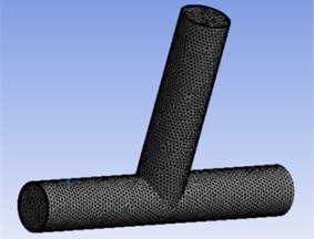
2. Geometric model and mesh generation
The quality of model meshing is very important for the correctness and accuracy of the results of a simulation. The outer diameter dimension of the T-shaped tube selected in this paper is 22 mm, the inner diameter is 20 mm. According to the structural characteristics of the T-shaped tube, the unstructured hexahedron is used to divide the T-tube, and the grid is divided into hexahedral mesh, as shown in Fig. 1.
Fig. 1Sketch of T-tube model meshing
3. Initial parameters and boundary conditions of T-tube
3.1. Initial parameter setting
Before the numerical analysis of the abrasive grain flow, the parameters in the calculated flow field need to be set, and combine the actual processing and numerical calculation. In the T-shaped tube abrasive flow polishing process, the processing medium is composed of solid abrasive and viscous liquid by a certain proportion of mixed. Among them, solid abrasive particles select silicon carbide particles, viscous liquid selection of oil. Among them, solid abrasive particles select silicon carbide particles, viscous liquid selection of oil. The role of oil is to make the silicon carbide particles evenly distributed in the fluid medium. And the specific settings of the initial calculation parameters of the model are shown in Table 1.
Table 1The initial calculation parameter table for the abrasive flow
Physical quantity | Numerical value | Explanation |
Liquid density | 1260 | In normal temperature (293.15 K) |
The dynamic viscosity of the liquid phase | 0. 08 | Change as the processing temperature changes |
The specific heat capacity of the liquid phase | 2000 | |
The thermal conductivity of the liquid phase | 0.15 | |
Density of SiC particles | 3100 | In normal temperature (293.15 K) |
The conductivity of SiC particles | 120 | |
Viscosity of SiC particles | 5e-6 | Small values can be ignored |
3.2. Boundary condition setting
Using LES large eddy simulation, Mixture multiphase flow model. The influence of abrasive grains on the polishing quality inside the pipe wall under different speed conditions was analyzed by using the speed import condition. The main phase selection of oil, the second phase selects the silicon carbide particles having a volume fraction of 0.2, import conditions using the speed of imports, and set the same import speed as the mixed phase. Because the abrasive flow processing outlet is connected to the external environment, so set the exit boundary conditions for free exit. And the wall condition selection without slip condition.
4. Results and analysis of numerical simulation
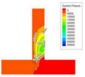
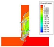
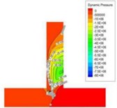
Based on the large eddy simulation method, and the numerical simulation is carried out according to the actual size parameters of the T-tube and the polishing condition of the abrasive flow. A lower port of the T-tube is selected as the inlet of the abrasive flow, and the upper port and the other lower port are the abrasive flow outlet. In order to further study the motion characteristics of abrasive grain polishing T-tube, the same particle size (30 μm) was selected to analyze the flow state of the abrasive grains under different speed conditions. It is mainly for the study of dynamic pressure, abrasive flow line and turbulent kinetic energy in the T-tube channel.
4.1. Dynamic pressure analysis at different import velocity
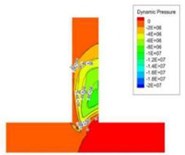
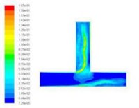
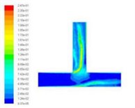
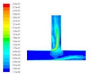
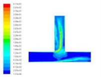
In order to obtain the effect of velocity on dynamic pressure, we obtain the simulation cloud diagram of dynamic pressure under different speed import conditions by numerical simulation, as shown in Fig. 2.
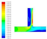
The dynamic pressure during the polishing process is the physical quantity associated with the velocity of the fluid, and it is caused by the movement of the fluid, its size has nothing to do with the reference pressure. As can be seen from Fig. 2, when the speed of the import increases, the pressure at the inlet will also become larger, and the change at the vertical crossing is obvious. In order to further analyze the change of dynamic pressure, the dynamic pressure equivalent curve under different speed conditions is given, as shown in Fig. 3.
As can be clearly seen from Fig. 3, with the speed increases, the dynamic pressure in the flow field increased accordingly, and the closer to the interface region, the greater the dynamic pressure. Dynamic pressure is the physical quantity that characterizes the velocity of motion, the dynamic pressure of the exit region is relatively large, we can predict the fluid movement here is more intense. Therefore, the polishing efficiency here should be higher, that is, the effect of deburring polishing is good.
Fig. 2Distribution of dynamic pressure distribution under different speed conditions
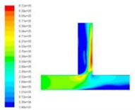
a)20 m/s
b)30 m/s
c)40 m/s
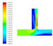
d)50 m/s
Fig. 3Dynamic pressure equivalence graphs at different speed conditions
a)20 m/s
b)30 m/s
c)40 m/s
d)50 m/s
4.2. Analysis of abrasive flow lines at different import velocity
In order to further study the flow mechanism of abrasive in the process of T-tube and the cross-section characteristics of different parts of T-tube, we have analyzed the abrasive flow lines at different positions inside the T-tube cross region, as shown in Fig. 4.
The background color in Fig. 4 represents the velocity distribution of the abrasive grains at different cross-sections, and the line indicates the trajectory of the abrasive flow in the cross section of the T-tube. As can be seen from Fig. 4, in the process of polishing the abrasive flow will appear double vortex phenomenon. Combined with the relevant theoretical analysis of fluid mechanics we can see, when the abrasive flow through the bending part of the pipe, it will produce centrifugal force, and the direction of the centrifugal force of the abrasive flow in the bending section is directed to the outside. By the impact of centrifugal force, the abrasive flow moves axially along the pipe and at the same time it has a velocity to flow to the outside of the pipe. As the abrasive flow has a continuous incompressible nature and it is bound by the wall of the pipe, when the abrasive flow in the central region flows outward, the abrasive grains near the inner wall of the pipe are forced to flow toward the central area of the pipe, and through the mutual flow to form a double vortex phenomenon. It will keep going until the velocity is reduced to a certain value.
Through the above analysis we can see, when the abrasive flow passes through the bending section of the tube, in addition to having axial movement, it also has a tangential vortex flow in the cross-sectional direction due to the influence of centrifugal force. When the abrasive flow produces a whirlpool flow in the bending section, the abrasive grains are thrown to the periphery of the whirlpool under the influence of centrifugal force and vortex flow. At the same time, the abrasive grain will produce tangential velocity in the vortex direction, so the abrasive grains in the axial and radial impact of the wall, while it will be grinding in the tangential direction of the tube on the wall. In the same cross-section, since the distance between the wall of the tube and the center of the vortex is different, the tangential velocity of the abrasive grains will be different. Therefore, in different positions on the same cross-section, the polishing effect will be different.
Fig. 4The distribution of abrasive flow lines in different positions of T-tube (different distances from the intersection)
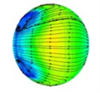
a) 0 mm
b) 20 mm
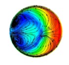
c) 30 mm

d) 40 mm
e) 50 mm
f) Exit
4.3. Analysis of turbulent kinetic energy at different import velocity
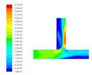
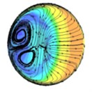
Turbulent kinetic energy is a measure of the turbulence intensity, the total kinetic energy of turbulence changes with time, it can measure the development and decline of turbulence. Among them, the total kinetic energy of turbulence changes with time, it can measure the development and decline of turbulence. The component turbulence kinetic energy is related to the turbulence diffusion variance, which can measure the turbulence mixing capacity. Select the different import speed for numerical simulation, we obtained the different inlet speed under the turbulence kinetic energy cloud chart, as shown in Fig. 5.
Fig. 5Turbulence kinetic energy cloud chart at different inlet velocities
a)20 m/s
b)30 m/s
c)40 m/s
d)50 m/s
From the numerical simulation results of turbulent kinetic energy, we can see that the turbulence kinetic energy of the T-tube intersection and the upper outlet is much larger than that of the lower channel. This indicates that when the T-tube is polished, the grinding media in the upper outlet and the intersection of the T-tube is more active, which facilitates the polishing and deburring of the upper outlet and the intersection. Thus, achieving the finishing of the abrasive flow, improving the quality of the inner surface of the T-tube.
5. Conclusions
As can be seen from the simulation results, with the increase of the import speed, the kinetic energy of the abrasive grains in the pipeline is also gradually improved, which is conducive to improving the polishing efficiency. But the speed cannot be too large, if the speed is too large will affect the processing quality. At the same time, in the process of polishing the T-tube, since the dynamic pressure at the intersection of the T-tube is large and there is a vortex flow, so the T-shaped tube at the intersection of the polishing effect is relatively good. Due to the grinding action of the abrasive grains, the larger the speed will produce a larger fillet at the intersection, this can effectively reduce the fatigue stress generated by high pulse and improve the fatigue strength. With the abrasive flow processing method can get the ideal surface quality, this method can enhance the reliability of parts and extend the service life.
In this paper, the dynamic pressure, abrasive flow line and turbulent kinetic energy of T-tube under different inlet speed are analyzed. The conclusion has important guiding significance for the practical work of T-tube machining by abrasive flow machining, and it provides a theoretical basis for the optimal selection of abrasive flow processing parameters.
References
-
Ji Shiming, Zhang Ding Simulation and experiment of precision machining of soft grinding flow. Electrical and Mechanical Engineering, Vol. 29, Issue 3, 2012, p. 245-248.
-
Li Dingpeng, Qian Jianping, Huang Weiping, et al. Numerical simulation of flow field in rotating drive. Ordnance Automation, Vol. 34, Issue 5, 2015, p. 14-17.
-
Guo Hao numerical simulation of key technique for thermodynamics of multi - linear coupled ground. Changchun University of Science and Technology, Changchun, 2014.
-
Li Junye, Xu Ying, Yang Lifeng, et al. Experimental study on grinding flow of non-linear tube parts. China Mechanical Engineering, Vol. 25, Issue 13, 2014, p. 1729-1733.
-
Li Junye, Liu Weina, Yang Lifeng, et al. Study of abrasive flow machining parameter optimization based on taguchi method. Journal of Computational and Theoretical Nanoscience, Vol. 10, Issue 12, 2013, p. 2949-2954.
-
Ji Shiming, Zhang Wei, Tan Dapeng Analytical method of sparse liquid - solid two - phase flow field based on phase field model. Electrical and Mechanical Engineering, Vol. 29, Issue 12, 2012, p. 1376-1381.
-
Yin Yanlu, Teng Qi, Li Junye, et al. Simulation analysis of abrasive flow field based on large eddy numerical simulation. Electrical and Mechanical Engineering, Vol. 33, Issue 5, 2016, p. 537-541.
-
Dong Liang, Liu Houlin, Dai Cui, et al. Application of different turbulence models in 90° elbow numerical simulation. Journal of Huazhong University of Science and Technology, Vol. 40, Issue 12, 2012, p. 18-22.
-
Zhang Zhaoshun, Cui Guixiang, Xu Chunxiao Theory and Application of Turbulent Large Eddy Numerical Simulation. Tsinghua University Press, Beijing, 2008.
-
Li Junye, Liu Weina, Yang Lifeng, et al. Numerical simulation of the behavior of grape flow in the micro - hole of injector. Coal Mine Machinery, Vol. 31, Issue 10, 2010, p. 56-58.
-
Yang Zhi Yin Large-eddy simulation: past present and the future. Chinese Journal of Aeronautics, Vol. 28, Issue 1, 2015, p. 11-24.
-
Guo Zhijun Large Eddy Simulation of Mixing Process of Hot and Cold Fluid in T-Tube. Beijing University of Chemical Technology, Beijing, 2009.
About this article

The authors would like to thank the National Natural Science Foundation of China No. NSFC 51206011, Jilin Province Science and Technology Development Program of Jilin Province No. 20160101270JC and No. 20170204064GX, Project of Education Department of Jilin Province No. 2016386.
