Abstract
Abrasive flow machining has become an efficient and economical ultra precision process for machining micro-bore parts. In this paper, aiming at viscosity temperature characteristics of abrasive flow finishing on micro-bore nozzle, under the guidance of the three governing equations of fluid mechanics theory, mixed phase model and discrete phase model were conducted, FLUENT software was resorted to simulate the discrete and fluid phase numerical characteristics of the solid-liquid two-phase flow field in the nozzle orifice with various field temperature and viscosity of slurry, the mechanism of erosion and wear of particles and effect of different processing parameters on particle erosion rate were uncovered, which provides a theoretical basis for the nozzle structure of abrasive flow machining.
1. Introduction
Abrasive flow machining is suitable for machining parts of myriad sizes including gears which diameter as small as 1 mm, spline channels large to 80 mm, and even the 1.5 m-sized turbine impeller [1, 2]. Fluid abrasive is termed as the cutting tools in abrasive flow machining characterized by its liquidity that can be enhanced when added softener, allowing it to reach the unaccessible area. Small holes, especially long, deep ones, are so hard to process that traditional machining methods are incompetent to perform [3, 4]. Accordingly, it is of great advantage to use abrasive flow to finish small holes (such as drawing dies, nozzles, air holes in blades, etc.).
Abrasive flow machining technology has been widely used in regions like aerospace, automotive, medical and machining automotive parts of locomotive: exhaust pipe, inlet valve, booster cavity, injector, cylinder head, turbine casing and blade, spline, gear, brake etc. [5, 6]. At present, scholars at home and abroad mainly study the abrasive flow machining method from the factors such as abrasive flow, working pressure and viscosity temperature characteristics. Dhirendra and fellow scholars have studied the direction of magnetic abrasive particles and discovered that solid magnetic particles can reduce viscosity of the flow [7-9].
2. Nozzle model with parameters
Over recent decades, researchers have carried out many theoretical and experimental studies on the complex two-phase flow system with nozzle small hole abrasive flow and constructed numerous mathematical models to solve numerically. In this study, based on the theory of solid-liquid two-phase flow dynamics, the mixed model, the discrete phase model and the erosion model, numerical simulation of viscosity and temperature characteristics of abrasive flow machining process were geared towards investigating the mechanism of micro abrasive removal by particles in the abrasive flow field and to reveal the effect of particle grinding in different positions along the nozzle flow passage and the influence of different processing parameters on particle erosion rate.
2.1. Creation of geometric models
Taking the nozzle body of servo valve as the object of study, build the fluid region model of the valve nozzle passage according to a physical model. The schematic diagram of the geometry model of the valve nozzle is shown in Fig. 1.
Fig. 1Sketch of geometric model of fluid area in nozzle
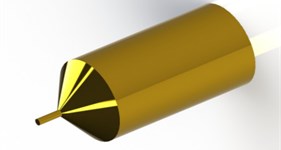
2.2. Physical parameters of nozzle
When applying abrasive fluid polishing technology on nozzle body, what is adopted as flow material is aviation hydraulic oil with a certain component proportion encompassing silicon carbide particles. In the calculation process, the aviation hydraulic fluid is regarded as a continuous phase fluid, the loose SiC particles, on the other hand, as discrete solid phases. Specific physical parameter settings are shown in Table 1 [10, 11].
Table 1Physical parameter table of abrasive medium
Parameters | Values | Condition specification |
Liquid density | 886 kg/m3 | Normal temperature |
Liquid dynamic viscosity | 0.131e-0.026t Pa·s | Changes with processing temperature |
Liquid relative heat capacity | 2000 J/kg·k | Normal temperature |
Liquid phase heat capacity | 0.15 W/m·k | |
Sic particle density | 3170 Kg/m3 | Normal temperature |
Thermal conductivity of sic particles | 120 W/m·k | |
Sic particle viscosity | 5e-6 Pa·s | Negligible |
3. Numerical simulation results and analysis
By analyzing the pressure at different speeds, the characteristics change curves of viscosity under various pressure differences are obtained. Then, the investigation on the influence of the above parameters on erosion efficiency is induced by temperature and viscosity analysis.
3.1. Pressure analysis at different speeds
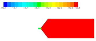
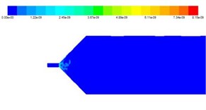
Regarding that pressure is an important factor affecting abrasive flow machining, it is essential to analyze the pressure distribution in the process of abrasive flow machining. The Mixed phase pressure diagram is shown in Fig. 2.
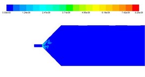
To obtain the influence of velocity on pressure, numerical simulation of static and dynamic pressure nephogram under different inlet conditions was obtained as shown in Fig. 3.
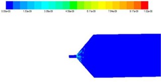
Fig. 2Mixed phase pressure diagram

The total pressure is the sum of static pressure and dynamic pressure. Static pressure is caused by the irregular movement of molecules in a fluid and its mass force, including pressure energy and gravitational potential energy; dynamic pressure is a physical quantity that is used to represent the velocity of fluid movement and is caused by the motion of fluid.
As can be seen from analysis above, the maximum pressure is observed at the entrance of the processing channel, and the pressure near the nozzle hole decreases gradually, whereas other areas of the polishing channel largely remain at the same pressure as the entrance. Moreover, the reduction of the pressure in the small hole region is due to the micro grinding action of the particles on the machined wall in the finishing process.
Fig. 3Static pressure distribution nephogram at different speeds

a) Inlet velocity 30 m/s

b) Inlet velocity 40 m/s
c) Inlet velocity 50 m/s
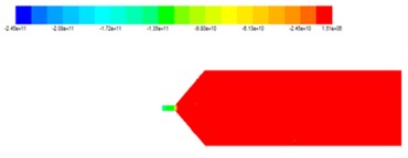
d)Inlet velocity 60 m/s
Fig. 4Nephogram of dynamic pressure distribution under different velocities

a) Inlet velocity 30 m/s

b) Inlet velocity 40 m/s

c) Inlet velocity 50 m/s

d) Inlet velocity 60 m/s
3.2. Numerical analysis of viscosity under various pressure differences
In order to thoroughly comprehend the machining characteristics of abrasive flow, they were numerically analyzed, thus obtained the velocity images shown in Fig. 5.
3.3. Investigation on influence of temperature and viscosity on erosion
3.3.1. Influence of viscosity on particle erosion
Considering the solid particles as discrete phase, the viscosity of the material has a great relationship with the amount of erosion. The viscosity of the selected material was set to be 3×10⁻⁶ kg/m·s, 5×10⁻⁶ kg/m·s, s, 7×10⁻⁶ kg/m·s and 9×10⁻⁶ kg/m·s, and the numerical simulation of erosion wear of nozzle abrasive flow polishing was carried out.
Fig. 5Viscosity nephogram under various pressure differences
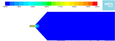
a) Inlet pressure: 3 MPa Outlet: 2 MPa
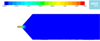
b) Inlet pressure: 5 MPa Outlet: 2 MPa
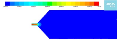
c) Inlet pressure: 8 MPa Outlet: 6 MPa
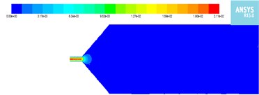
d) Inlet pressure: 9 MPa Outlet: 6 MPa
The analysis shows that the particle erosion rate increases with the increase of material viscosity. The increase of viscosity in the polishing channel results in the enhancement of the flowability of the grinding medium, leading to the increase of the activity between the particles and eventually the motion of the particles. Therefore, the abrasion rate of the particles to the machined wall surface is increased, and the processing effect is improved.
Fig. 6Effect of viscosity on particle erosion
a) 3×10⁻⁶ kg/m·s viscosity
b) 5×10⁻⁶ kg/m·s
c) 7×10⁻⁶ kg/m·s
d) 9×10⁻⁶ kg/m·s
3.3.2. Influence of temperature on particle erosion
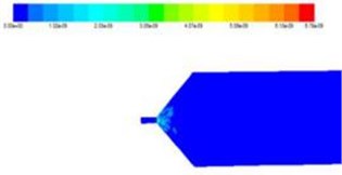
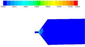
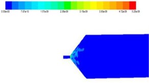
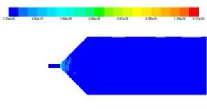
The increase of temperature in the nozzle passage of the valve core is due to the frictional heat produced by the surface of the machined surface. The increase of temperature will affect the movement of fluid and particles and the polishing effect. The initial polishing temperature is set to be 290 K, 300 K, 310 K and 320 K, respectively. By the numerical simulation of the flow field of the nozzle and the abrasive flow of the nozzle, the curves of the particle wear and the curves of temperature and wear rate under different temperatures were obtained shown as in Fig. 7.
It can be concluded that with the increase of temperature, the erosion rate of particles increases. In the process, the elevated temperature in the polishing channel results in enhanced flowability of the abrasive medium, accordingly increases the intensity of motion between particles. The wear rate of the particles on the machined wall increases and the processing effect is improved, but an excessive higher temperature will lead to a decrease in wear rate.
Fig. 7Erosion nephogram of particles under different temperature conditions
a) Initial temperature290 K

b) Temperature 300 K
c) Temperature 310 K
d) Temperature 320 K
4. Conclusions
By analyzing the pressure and velocity distribution characteristics of the simulation model, it is concluded that the machining effect at entrance of the small hole and cross hole region is better than elsewhere. Through the discrete phase model, the effects of viscosity and temperature on particle erosion and particle wear rate were further investigated. It is found that the viscosity of the particles in positive correlation to the flow velocity in the orifice of the nozzle, whereas negative correlation to the pressure. Moreover, with the increase of inlet velocity, initial temperature or viscosity of flow material, the response of particle erosion rate all shows an increasing tendency, which is beneficial to the machining efficiency.
References
-
Sun Fengyu, Wei Lili, Li Junye, Zhang Xinming, Xu Ying The single factor experiment of the non-linear tube in abrasive flow machining. Journal of Measurements in Engineering, Vol. 5, Issue 1, 2017, p. 11-18.
-
Li Junye, Hu Jinglei, Zhang Xinming, Zhao Weihong The research of polishing nozzle quality based on discrete element method. Journal of Measurements in Engineering, Vol. 5, Issue 1, 2017, p. 29-39.
-
Li Junye, Wei Lili, Zhang Ximing, Hu Jinglei, Su Ningning Quality analysis of T-tube with solid-liquid two-phase abrasive flow polished. Journal of Measurements in Engineering, Vol. 5, Issue 2, 2017, p. 77-86.
-
Li Junye, Su Ningning, Zhao Weihong, Yin Yanlu, Hu Jinglei Study on the polishing of curved pipe parts by solid liquid two phase abrasive flow. Journal of Measurements in Engineering, Vol. 5, Issue 2, 2017, p. 59-67.
-
Ji Shiming, Zhang Ding Simulation and experiment of precision machining of soft grinding flow. Electrical and Mechanical Engineering, Vol. 29, Issue 3, 2012, p. 245-248.
-
Zhang Zhaoshun, Cui Guixiang, Xu Chunxiao Theory and Application of Turbulent Large Eddy Numerical Simulation. Tsinghua University Press, Beijing, 2008.
-
Dong Liang, Liu Houlin, Dai Cui, et al Application of different turbulence models in 90° elbow numerical simulation. Journal of Huazhong University of Science and Technology, Vol. 40, Issue 12, 2012, p. 18-22.
-
Yang Zhi Yin Large-eddy simulation: past present and the future. Chinese Journal of Aeronautics, Vol. 28, Issue 1, 2015, p. 11-24.
-
Junye Li, Lili Wei, Ximing Zhang, Jinglei Hu, Ningning Su Quality analysis of T-tube with solid-liquid two-phase abrasive flow polished. Journal of Measurements in Engineering, Vol. 5, Issue 2, 2017, p. 77-86.
-
Junye Li, Jinglei Hu, Xinming Zhang, Weihong Zhao The research of polishing nozzle quality based on discrete element method. Journal of Measurements in Engineering, Vol. 5, Issue 1, 2017, p. 29-39.
-
Li Dingpeng, Qian Jianping, Huang Weiping, et al. Numerical simulation of flow field in rotating drive. Ordnance Automation, Vol. 34, Issue 5, 2015, p. 14-17.
About this article

The authors would like to thank the National Natural Science Foundation of China No. NSFC 51206011, Jilin Province Science and Technology Development Program of Jilin Province No. 20160101270JC and No. 20170204064GX, Project of Education Department of Jilin Province No. 2016386.
