Abstract
In order to study the performance of abrasive flow polishing on the micro-holes, the polishing process of abrasive flow with different abrasive particle sizes was carried out by using computational fluid dynamics. The distribution of fluid turbulence intensity and abrasive particle velocity, fluid turbulence dissipation rate and kinetic energy of abrasive particles were obtained and analyzed. The simulation reveal that the material removal rate is proportional to the size of abrasive particle size, while the surface quality is inversely proportional to it. Therefore, the appropriate size of abrasive particle should be selected according to the initial surface roughness of the workpiece. The research results have certain guiding significance for practical production.
1. Introduction
As a common mechanical product, micro-holes are widely used in all walks of life, such as industry, agriculture, medical equipment and so on [1-3]. Because of the working environment and the using requirements of micro-holes, the surface quality of micro-holes is required to be high. However, on account of small aperture of micro-hole parts, it is difficult for traditional polishing technology (such as mechanical polishing, Chemical polishing, Electrolytic polishing, ultrasonic polishing, etc.) to polish effectively [4-6]. How to realize high efficiency and high-quality machining of micro - hole parts is an important technical problem. The abrasive flow polishing can be used to polish micro- holes because of its good fluidity and consistency [7, 8]. Therefore, scholars put lots of efforts into studying mechanism and key technology of it and got many achievements [9, 10].
In this paper, the numerical simulation analysis of abrasive flow polishing process with different abrasive particle sizes was carried out by using computational fluid dynamics when the inlet velocity and abrasive concentration are constant, and the research results have certain guiding significance for practical production.
2. Mathematical model of abrasive flow polishing
Turbulence kinetic energy is mainly used to describe the intensity of turbulence. In the near-wall region of polishing, it can also be equivalent to the disordered motion of abrasive particles. The greater the turbulent kinetic energy, the stronger the disorder of abrasive motion, the less directional fringes will be formed on the workpiece surface. In order to improve the accuracy of numerical simulation analysis, one of the most important things is to select a suitable turbulent model. The standard - model is chosen to describe the turbulence and its formulas are as follows:
where is the density of fluid, is the coefficient of molecular viscosity, is the coefficient of turbulent viscosity, is turbulent kinetic energy generated by laminar flow velocity gradient; is turbulent kinetic energy generated by buoyancy, where the empirical coefficients: 1.44, 1.92, 0.09, 1.0 and 1.3.
For a certain Newtonian fluid, the fluid viscosity is closely related to temperature, and its functional relationship is as follows:
where is the initial molecular viscosity. From Eq. (3), it can be seen that the higher the temperature is, the lower the viscosity will be, and the more violent the molecular motion will be.
3. Numerical analysis of abrasive flow polishing
3.1. Geometric model and meshing
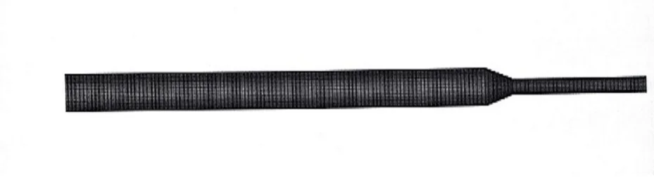
For the sake of facilitating later analysis of the numerical variation trend of each position of the micro hole, the micro hole was divided into three regions with different diameters: the diameter of large hole region is 1.2 mm, the variable diameter region and the diameter of small hole region is 0.5 mm. The solid-liquid two phase liquid enters from the large hole region and flows out from the small hole region as show in Fig. 1.
The structure of micro hole is meshed by unstructured hexahedral using ICEM in the FLUENT software as show in Fig. 2.
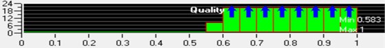
To inspect the mesh grid of micro hole is to get higher quality grid. Fig. 3 shows the results of checking the mesh quality. The mesh quality is greater than 0.5, which can ensure the accuracy of numerical simulation.
Fig. 1Schematic diagram of micro hole polishing channel area division
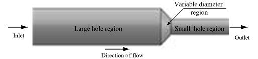
Fig. 2The grid model of micro hole
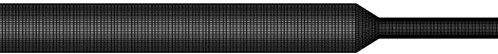
Fig. 3The quality inspection of micro hole
3.2. Boundary condition setting
Because the outlet is connected with the outside environment, so exit boundary is set as a free boundary. Because two ends of the workpiece are fixed by clamps, so define other wall as the solid wall without slip. The process of simulation is transient. The command of Track Collision is turned on. The length of time step is 2E-7 s and the simulation time is1s. Finally, gravity acceleration should be taken into account.
4. Analysis of simulation results
The numerical simulation of polishing process with different abrasive particle sizes was carried out. According to the actual processing conditions, set the abrasive concentration at 10 % and the inlet speed at 60 m/s. The particle sizes of 300 mesh (48 μm), 400 mesh (38 μm) 500 mesh (25 μm) and 800 mesh (18 μm) were selected for numerical simulation analysis.
4.1. The analysis of fluid turbulence viscosity at different abrasive particle size
The cloud diagram of fluid turbulence intensity and abrasive velocity distribution under different abrasive particle sizes is shown in Fig. 4.
As shown in Fig. 4, with the increase of mesh of the abrasive particle, the turbulent viscosity of the fluid decreases slightly, but the abrasive velocity increases slightly. This is because the smaller particles have better following property to the fluid and have the faster velocity so that it can achieve more uniform polishing effect.
The turbulent viscosity in the near wall region is smaller than that in the middle region of the channel, which indicates that the number of abrasive particles near the wall is less. That is because abrasive particles bounce back to the middle region after polishing.
Fig. 4Fluid turbulence viscosity and abrasive velocity distribution of abrasive particles under different abrasive particle size conditions
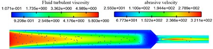
a) Abrasive particle size of 300 meshes
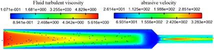
b) Abrasive particle size of 400 meshes
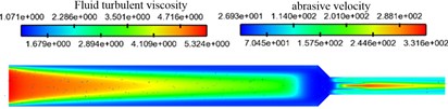
c) Abrasive particle size of 500 meshes
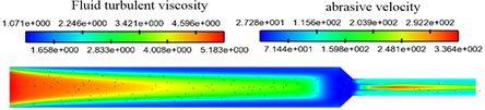
d) Abrasive particle size of 800 meshes
4.2. The analysis of discharge dissipation rate of fluid turbulence at different abrasive particle size
Turbulent dissipation rate is the rate at which turbulent kinetic energy of fluid is converted into kinetic energy of molecular thermal motion. Under the same initial conditions, the fluid turbulent dissipation rate and the kinetic energy of abrasive particles were coupled numerical simulation analysis under different particle sizes. The cloud diagram of discharge dissipation rate of fluid turbulence and kinetic energy distributions of abrasive particles under different abrasive particle size conditions is shown in Fig. 5.
Fig. 5Discharge dissipation rate of fluid turbulence and kinetic energy distributions of abrasive particles under different abrasive particle size conditions
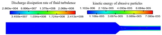
a) Abrasive particle size of 300 meshes
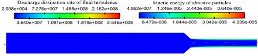
b) Abrasive particle size of 400 meshes
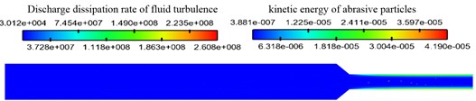
c) Abrasive particle size of 500 meshes
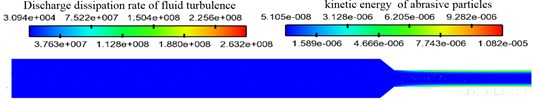
d) Abrasive particle size of 800 meshes
As can be seen clearly from the Fig. 5, with the mesh of abrasive particles increase, the numerical value of fluid turbulence dissipation rate increases slightly. The region with the largest turbulent dissipation rate is mainly located near the wall. The reason for this phenomenon is that the collision of abrasive particles near the wall is intense, and the abrasion occurs with the wall, which leads to the increase of turbulent dissipation rate near the wall.
It can be seen from the distribution diagram of abrasive kinetic energy that the kinetic energy of abrasive particles in the large hole region is smaller than in the small hole region, but the kinetic energy of abrasive particles does not change regularly under different particle sizes. This is because the particle size decreases, the abrasive mass decreases, and the abrasive velocity increases, so the kinetic energy cannot determine the change rule. Under the same abrasive velocity, the material removal rate is proportional to the particle size.
5. Conclusions
In this paper, the numerical simulation of micro-holes polished by abrasive flow is carried out by means of computational fluid dynamics. The distributions of turbulent dissipation rate and kinetic energy, turbulent viscosity and velocity of abrasive particles in micro-holes with different abrasive particle sizes are analyzed. The results of numerical simulation show that the improvement of material removal rate and surface quality depends on the size of abrasive particles. Under certain other conditions, the material removal rate is proportional to the size of abrasive particle size, while the surface quality is inversely proportional to it. Therefore, the appropriate abrasive particle size should be selected according to the initial surface roughness of the workpiece. This research results have certain guiding significance for practical production.
References
-
Junye Li, Zengwei Zhou, Xinming Zhang, et al. Numerical analysis and experimental study on micro-holes in solid-liquid two-phrase abrasive flow machining. Journal of Measurements Engineering, Vol. 5, Issue 3, 2017, p. 176-181.
-
Li Junye, Su Ningning, Hu Jinglei, Yang Zhaojun, Sheng Liang, Zhang Xinming Numerical analysis and experiment of abrasive flow machining microhole structure based on CFD-DEM coupling. Transactions of the Chinese Society of Agricultural Engineering (Transactions of the CSAE), Vol. 34, Issue 16, 2018, p. 80-88, (in Chinese).
-
Zhang Yang, Di Zhu, Xu Zhengyang Basic research on EDM-ECM machining of micro hole. Journal of Mechanical Engineering, Vol. 54, Issue 1, 2018, p. 26.
-
Gudipadu V., Sharma A. K., Singh N. Simulation of media behaviour in vibration assisted abrasive flow machining. Simulation Modelling Practice and Theory, Vol. 51, Issue 51, 2015, p. 1-13.
-
Kheradmand S., Esmailian M., Fatahy A. Numerical simulation of the combination effect of external magnetic field and rotating workpiece on abrasive flow finishing. Journal of Mechanical Science and Technology, Vol. 31, Issue 4, 2017, p. 1835-1841.
-
Brar B. S., Walia R. S., Singh V. P. Electrochemical-aided abrasive flow machining (ECA2FM) process: a hybrid machining process. International Journal of Advanced Manufacturing Technology, Vol. 79, Issues 1-4, 2015, p. 329-342.
-
Cherian Jose, Issac Jeoju M. Effect of process parameters on wear performance in abrasive flow machining. Applied Mechanics and Materials, Vol. 766, Issue 767, 2015, p. 661-667.
-
Uhlmann E., Schmiedel C., Wendler J. CFD simulation of the abrasive flow machining process. Procedia Cirp, Vol. 31, 2015, p. 209-214.
-
Kumar Santhosh Sa, Hiremathb Somashekhar S. A review on abrasive flow machining (AFM). Procedia Technology, Vol. 25, 2016, p. 1297-1304.
-
Liu Weina, Wang Yinchen, Zhang Yingzhi, et al. Abrasive flow machining analysis and research of nozzle. Journal of Chongqing University of Technology (Natural Science), Vol. 32, Issue 1, 2018, p. 81-85, (in Chinese).
About this article

The authors would like to thank the national natural science foundation of china No. NSFC 51206011, Jilin province science and technology development program of Jilin Province No. 20160101270JC and No. 20170204064GX.
