Abstract
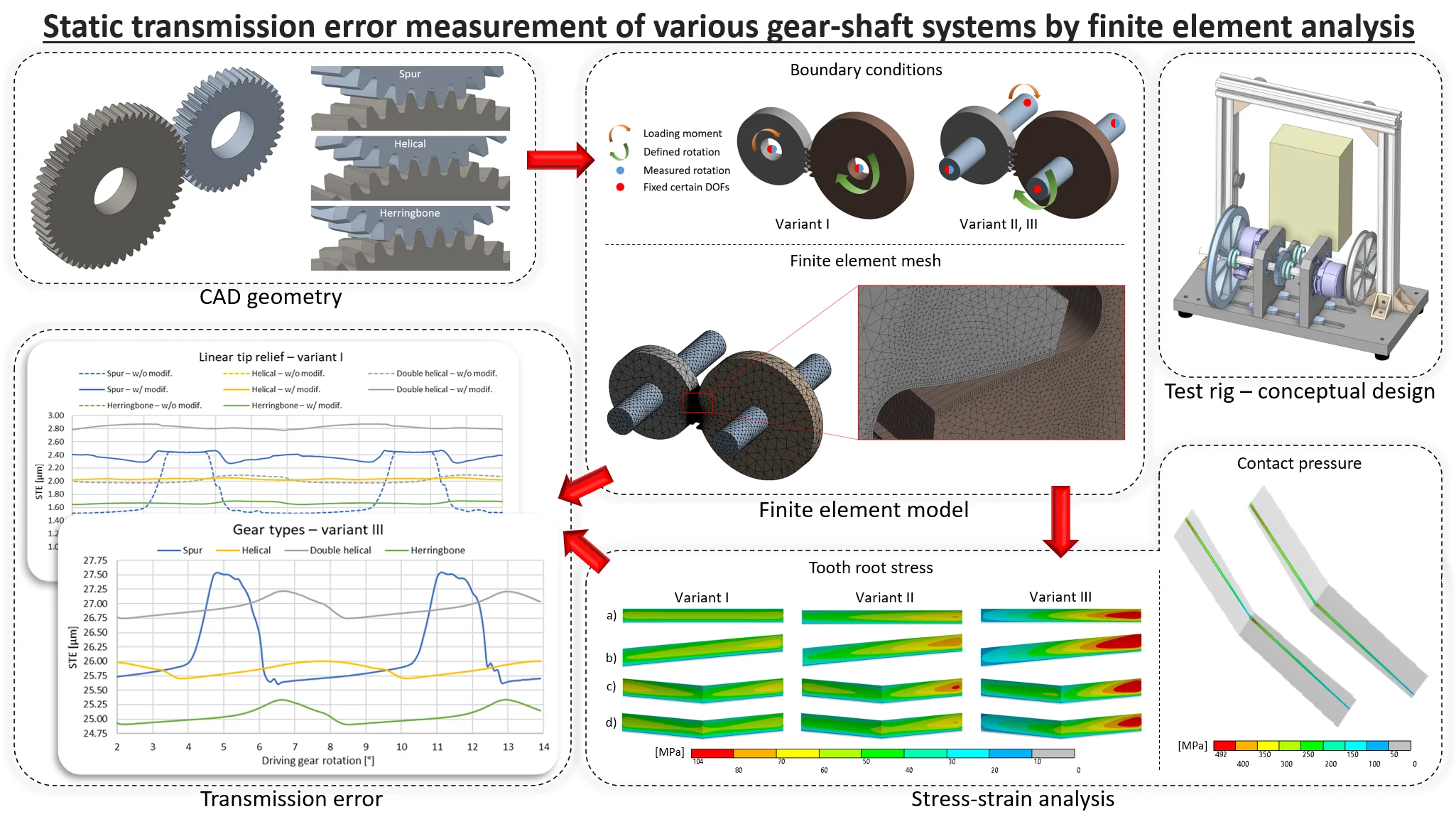
Transmission error (TE) is a significant parameter related to gears vibration widely investigated by many authors using different approaches. However, in previous studies, spur and helical gears were mainly examined. There is a lack of studies addressed to double helical and herringbone gears and a comparison among several types of gearing with parallel axes. In this paper, spur, helical, double helical, and herringbone gears are analyzed in terms of static transmission error (STE), contact pressure and tooth root stress. Static contact analyses were conducted using the finite element method (FEM) which is often considered a tool for validating other methods and approaches. Moreover, three variants of boundary conditions of each gear type are introduced, including flexible shafts and the effect of a tip relief modification at sole gears, without shafts, was analyzed. In addition, a concept of a compact test rig intended for STE measurements at low loads was presented. The results have shown, among other things, significant influence of the shaft stiffness and boundary conditions on meshing characteristics.
Highlights
- Moderate increase in mean and peak-to-peak values of STE; and uneven load distribution along gear width by adding shaft flexibility and significant increase in mean and peak-to-peak values of STE; and more uneven load distribution by allowing all rotational DOFs of shaft ends.
- Marked difference between the double helical and herringbone gears in terms of mean values of STE, contact pressure and tooth root stress across all variants.
- Higher peak-to-peak STE values of the herringbone-like gears compared to the helical ones due to half overlap ratio at the same parameters.
- Most pronounced decrease in STE fluctuations by introducing a long tip relief modification in case of the spur gears.
- Lower positive effect of the modification at the double helical gears than the herringbone ones.
1. Introduction
Gears, components still widely used in industry, and their meshing are a dominant source of transmission systems vibration and noise. A parameter called Transmission Error (TE) is closely related to it. It can be determined by various approaches, including analytical, empirical, numerical, experimental, or a hybrid one. Although the transmission error is a parameter related to the gearing, it is also affected by adjacent components such as particular shafts, bearings, and housing. In addition, it is influenced by load [1], [2], [3], misalignments [4], [5], different types of tooth damage [6], [7], [8], and micro-geometry in the form of intended modifications [4], [9], [10] and unwanted machining errors [4], [11].
Many authors dealt with the transmission error, or the time-varying mesh stiffness (TVMS) which is associated with it, by considering only sole gears or teeth. Bartošová et al. [12] determined the static transmission error (STE) of spur gears using the finite element method (FEM). Among other things, they investigated the influence of loading torque, center distance and micro-geometric modifications. Fraňová et al. [13] used the same approach to obtain STE of spiral bevel gears with various parameters of the tip relief modification. In addition to the modifications, Zhao et al. [5] explored the effect of angular and axial misalignments and changes in the center distance on STE and TVMS, and noted a significant effect, especially of axial misalignment, on these characteristics. Liu et al. [4] proposed a method to determine the TVMS based on the accuracy grade or measured coordinates of the real surface of the tooth flank (spur and helical gear). They considered the single and cumulative pitch deviation, total profile and helix deviation, and the deviation of the tooth thickness for three accuracy grades according to ISO 1328-1:2013. Liang et al. [6] created a mathematical model of TVMS of pitted spur gears and examined the relationship between the mesh stiffness and pitting severity. The model was validated by FEA without using contact elements. Mesh nodes of both gears were coupled instead to make the analysis linear. Li et al. [7] studied three types of tooth root cracks in spur gears. An analytical method based on potential energy was used and validated by a FEM model. They analyzed the effect of crack dimensions (depth, height, and width) on TVMS, concluding the depth having the most and the height having the least influence. Regarding double helical gears, Yang et al. [14] proposed a calculation method for TVMS, tooth surface load, and other parameters related to dynamics, of modified gears by 3D (combined) modification with different parameters. They verified the method by a dynamic FEM model in LS-DYNA software. Zou et al. [10] presented an improved algorithm of topographical modification of double helical gearing (although a term “herringbone” was used) based on overlap ratio and verified its benefit in terms of statics and dynamics. They used mathematical models for determination of TVMS, STE, dynamics, and static finite element analysis (FEA) for contact pressure.
The higher level of models comes with addition of shafts and their stiffnesses and moving boundary conditions from gear centers to shaft ends. Y. Benaïcha et al. [2] conducted transient FEA at quasi-static conditions (1 rpm) of modified spur and helical gears without and with flexible shafts, and with different gear bodies. In their study, a very fine mesh in contact zones was used but with linear elements. Liu et al. [15] created a multibody dynamic model for contact analysis of helical gear-shaft systems where the shafts were represented by 3D Timoshenko beam elements and the gears by Arbitrary Lagrangian Eulerian formulation. Zhao et al. [16] simulated a locomotive helical gear pair, including shafts and damaged teeth, by explicit FEM to capture its transient, dynamic behavior during meshing. The model included connection between the sprung masses and ends of the driven shaft (axle) by springs and dampers as well. Fernández-Del-Rincón et al. [3] improved a mathematical non-linear dynamic model used for investigation of spur gear transmissions vibration which included bearing and shaft parameters too. The model was extended by index and run out errors as well as eccentricity. Ye and Tsai [17] developed a mathematical model for loaded tooth contact analysis (LTCA) of high contact ratio (HCR) modified spur gears which considered shaft misalignment and twist deformation, and tip corner contact. The results were compared with FEM model when the output gear was fixed, and the input pinion could only rotate about its own axis. Lin and He [11] created a static FEM model of helical gear-shaft system with microgeometry and assembly errors, consisting of one output and two input shafts, for STE determination. Based on the resulting STE, they studied dynamic TE using a mathematical model of 12 degrees of freedom.
Models considering gearbox housing are closest to reality but are the most computationally demanding and less frequented. Duan et al. [18] proposed a rigid-flexible coupling dynamic model considering engagement of a spur gearing, flexible shafts, and bearing using a lumped mass element, beam element, and spring element, respectively. Housing flexibility was represented by condensed model which was verified by an experimental modal analysis. Liu et al. [19] approached the issue similarly. Moreover, they included a tooth root crack of spur gears. Yuan et al. [20] and Liu et al. [21] obtained, among other things, the housing stiffness of double helical gear system by FEM. Kučera et al. [22] included the housing of a heavy-duty gearbox in a technical experiment and measured the quasi-static transmission error by using a closed-loop test rig.
Based on the literature review, it has been shown that most authors deal with gear transmission error or mesh stiffness of sole spur and/or helical gears in case of gears with parallel axes. Publications regarding double helical gears are less frequent and publications regarding herringbone gears are rare. A comparison of spur, helical, double helical, and herringbone gears without and with shafts in terms of TE or TVMS, is also missing. Therefore, this study aims to compare meshing characteristics of the mentioned four types of gears, including a tooth profile modification, at different boundary conditions using FEM which is often used as a benchmark to other methods.
2. Theoretical background
2.1. Transmission error
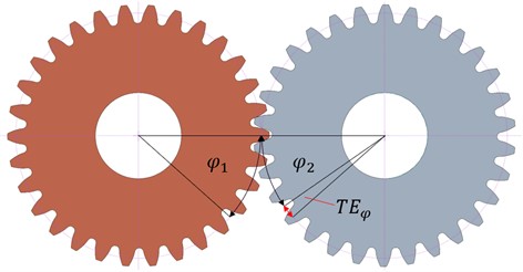
Meshing gears would not generate any vibration if the gears were perfectly manufactured (ideal involute tooth flanks), without assembly inaccuracies, and perfectly rigid including all adjacent components (shafts, bearings, housing). In reality, this is not the real case, therefore the term transmission error was introduced in the 1950s (at Cambridge) [23], [24]. The transmission error can be defined as the difference between the theoretical (ideal) and actual angular position of the driven gear/shaft:
where and is the angular displacement of the driving and driven gear respectively, and is the transmission ratio. Concept of the transmission error is shown in Fig. 1. Note that the angle is magnified for better clarity.
Fig. 1Concept of the transmission error
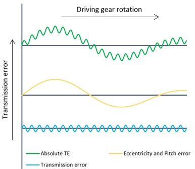
The experimentally measured waveform of the transmission error is referred to as the absolute (total) transmission error [1], [8]. It can be decomposed into two components. The component that is periodic with the mesh period is called transmission error and the difference between its maximum and minimum (peak-to-peak) value is a very important parameter in terms of vibration and subsequent noise [25]. It is used as a parameter for comparison across all approaches. It is modulated on the component which is caused by the gear eccentricity [26] and pitch error [3]. These components are shown in Fig. 2.
Fig. 2Transmission error components
The resulting values of the transmission error in angular units are usually converted to length units (microns) by multiplying the angular displacements in radians by the radius of the base or pitch circle – Eq. (2). The advantage of this conversion is better comparability, since gears of the same accuracy, regardless of their module and number of teeth, have approximately the same peak-to-peak (PTP) value of the transmission error [25]:
where is the base circle radius of the driven gear.
In terms of measurement conditions, the transmission error can be divided into:
– Geometric (kinematic, machining) Transmission Error – GTE, e.g., [4], [11].
– Static Transmission Error – STE, e.g., [2], [27].
– Dynamic Transmission Error – DTE, e.g., [9], [26].
The geometric transmission error is determined at very low speeds and (almost) no load. Therefore, only tooth surface imperfections, intentional micro-geometric modifications, and assembly errors are included in it. In the static transmission error, the influence of elastic deformations, caused by the loading operating torque, appears while the speed remains still low. The influence of inertial effects at higher speeds is only considered in the dynamic transmission error, which is the most complex type, which is also related to the high difficulty of its determination.
Gears can be tested on special test rigs with the open or closed power circuit. These rigs can be used to investigate various gear faults, lubrication, efficiency/losses, service life and, last but not least, to measure transmission error, vibration and noise. In order to measure the transmission error, the test rig has to additionally be equipped with sensors that are suitable for this:
– rotary encoders (optical, magnetic),
– laser vibrometers,
– accelerometers (torsional, tangentially attached).
2.2. Micro-geometric modifications
Micro-geometric modifications are a subset of deviations from the ideal tooth shape. Unlike machining errors, they are intentionally designed. Their task is mainly to compensate for deformation of gearing and shafts, and thus minimize fluctuations (PTP values) of the transmission error and mesh stiffness, which generate vibrations. They are designed for the given load, in the case of incorrect design or different loads, they can, on the contrary, worsen the quality of the engagement. They can be divided into two main groups – tooth profile and flank line modifications, or their combination. Tooth profile modifications serve primarily to compensate for teeth deformation and to avoid a corner contact, flank line modifications serve to compensate for shaft deformation and assembly inaccuracies.
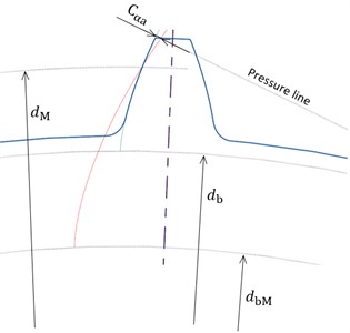
Tip relief, used in this study as well, is a frequently used tooth profile modification. It can take several forms – linear, parabolic and others. Linear tip relief is linear in terms of roll distance (see Fig. 3(a)). From the geometry point of view (see Fig. 3(b)), it is an involute with a different base circle and pressure angle. It is defined by its amount and length . The amount is measured on the pressure line (tangent to the base circle with diameter ). The diameter of the beginning of the modification corresponds to its length .
The modification amount depends on the maximum load [28]:
where is maximum allowed tangential force, is gear width, represents specific mesh stiffness and is transverse pressure angle.
The modification length depends on the design load [28]:
where is the length of path of contact, represents base pitch and is design tangential force.
Modifications are designed for a single load where the lowest transmission error fluctuation is desired. With different operating loads, their influence may be less dominant or, on the contrary, worse. When the design load is equal to the maximum one, the modification length is equal to the difference between the length of the path of contact and the basic pitch , i.e., long tip relief.
Fig. 3Linear tip relief
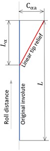
a) Roll distance
b) Tooth geometry
3. Methods
3.1. Geometry of gears
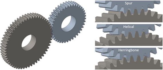
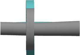
To simulate the gear engagement, parametric geometry of spur, helical and herringbone gears was created first – see Fig. 4. It included the possibility of applying addendum modifications (corrections) and micro-geometric modifications of linear tip relief and/or root relief. The corrections were designed so that the same center distance was retained for all three types of gearing and the backlash was created as well. This was done due to possibility of machining the same gears in the future, and implementation of a technical experiment using a test rig with the fixed center distance.
Fig. 43D models of the designed gears
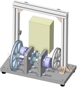
The test rig (see Fig. 5) will be an open loop concept where the role of a motor and brake will be replaced by a weight attached to a rope. The rope will be wound on pulleys that will be fixed at the opposite ends of the driving and driven shafts (rotary incremental encoders will be placed at the other ends). The force created by the weight will be transmitted through the rope to the pulleys and shafts and will cause both shafts to rotate in the same direction, thus loading the teeth. The resulting loading moment depends on the weight mass and the radius of the pulleys – in this study 5.64 N·m which corresponds to the weight mass of 20 kg.
Fig. 5Conceptual design of the test rig
Linear tip relief was designed for one value of the load (5.64 N·m), based on the total deformation of the meshing gear teeth without modification under the given load. The width of the gears was chosen the same for all types of the gear pairs and the helix angle was chosen for the helical and herringbone gears for better comparability of results. The diameter of both shafts was 12 mm, and the length was 80 mm, while the gear pairs were located at the distance of three eighths of the total length of the shafts. Basic parameters of the gears are listed in Table 1.
Table 1Basic parameters of the designed gears
Parameter | Unit | Spur | Helical | Herringbone |
Normal module | mm | 1 | ||
Number of teeth (input/output) | – | 57/41 | ||
Normal pressure angle | ° | 20 | ||
Helix angle (input/output) | ° | 0 | 12/–12 | 12 |
Profile shift coefficient (input/output) | – | –0.122/0 | –0.722/–0.400 | |
Addendum coefficient | – | 1 | ||
Tip clearance coefficient | – | 0.25 | ||
Gear width | mm | 8 | ||
Working center distance | mm | 49 | ||
Contact ratio | – | 1.647 | 1.924 | |
Overlap ratio | – | 0 | 0.529 | 0.265 |
Besides the herringbone gears, the engagement of double helical gears was also analyzed. This gearing was based on the same geometry as the herringbone one, but was split in half, and there was no interaction between the left and right part. This was done because of the planned production of the designed gears, while the machining of gears with a low module is very difficult, and therefore the approach of two helical gears with opposite helices placed next to each other will be chosen. So, it is important to investigate the impact of this arrangement as well.
3.2. Numerical simulations of gear engagement
A very common approach to determine the transmission error (or mesh stiffness) is finite element analysis (FEA) based on the finite element method (FEM). It is characterized by its versatility and relatively high accuracy. However, a contact analysis requires a fine finite-element mesh resulting in high demands on hardware and computing time. Therefore, it is mainly used for validation of other methods and for inclusion of more complex effects which are neglected in other methods.
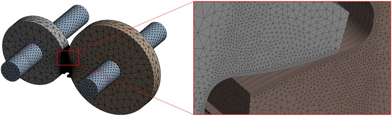
Created geometry was subsequently imported into the FEM software Ansys Workbench, where all quasi-static structural simulations were carried out. Five teeth were modeled on each gear, since the rotation of the gears by only a fraction of a full revolution – at least by one pitch – was sufficient to determine the static transmission error. Material of the gears and shafts was structural steel with Young’s modulus of 200 GPa and Poisson ration of 0.3. It was necessary to create a suitable finite-element mesh (see Fig. 6) for a contact analysis of the gear engagement. The contact region on the tooth flanks and the tooth roots consisted of two layers of hexahedral quadratic elements with dimensions in the transverse plane (0.03 × 0.03) mm. In the axial direction, the element size was larger (50 elements along the gear width) with respect to the size of result files and the length of computational time. In addition, the mesh was mapped in these areas and the sweep method was used. The remaining volume of the gears and shafts was meshed with tetrahedral quadratic elements. This approach corresponds to the previous work of the authors [29], and is similar to other publications of the scientific field, e.g., [2], [30].
Fig. 6Finite-element mesh of the gear-shaft system
In order to ensure transfer of the load between the gears, it was necessary to set contacts between the tooth pairs on their active flanks. Properties of the contacts were the same for all performed simulations for better comparability of the results. The Augmented Lagrange formulation was used with the normal stiffness factor of 1, penetration tolerance value of 0.002 mm and friction coefficient of 0.1.
Regarding boundary conditions, the performed simulations can be divided into three variants:
I. gears without shafts, placed in their centers and with 1 degree of freedom (DOF) allowed – rotation about axes of rotation,
II. gears with shafts, constrained on the ends of the shafts (at location of theoretical bearings) with 1 DOF allowed – rotation about axes of rotation,
III. gears with shafts, constrained on the ends of the shafts (at location of theoretical bearings) with 3 DOFs allowed – rotation about all three axes.
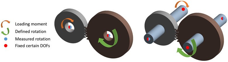
All variants were loaded with the moment of 5.64 N·m on the driven part, which acted against the defined angular displacement of the driving part (see Fig. 7). The rotation of the driven part was dependent on the rotation of the driving part based on the contacts. The angular displacement increment was set to 0.1° to capture all peaks and obtain smooth curves of the TE. At the given locations, the angular displacements about (undeformed) gear/shaft axes of rotation were evaluated using the command, and using Eqs. (1-2), a graph of the transmission error was obtained depending on the rotation of the driving part. Initial simulations were performed for the purpose of a sensitivity study of the effect of mesh element size, contact settings, and rotation increment on the results.
Fig. 7Boundary conditions of the gear-shaft system
4. Static transmission error and stress-strain analysis
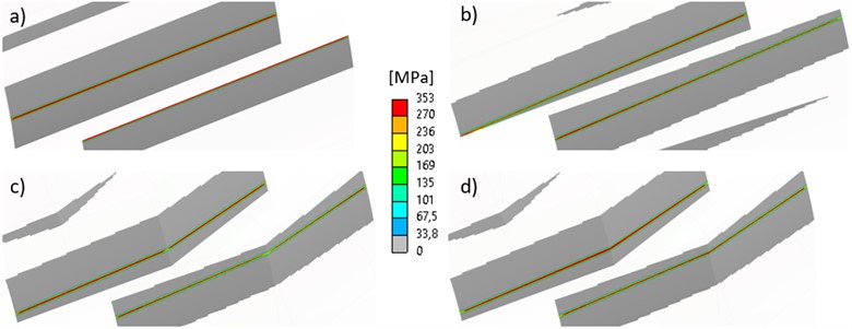
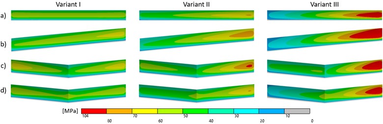
First, the engagement of spur, helical, and herringbone gearing without shafts placed in their center (variant I), was simulated, and compared in terms of STE curves – see Fig. 8 (note that there is a different range and scale for the spur, and helical and herringbone gears). The period of the STE corresponds to the tooth pitch of the driving gear, i.e., 6.32°. At the spur gears, one and two tooth pairs alternate in the mesh, and lower STE (higher mesh stiffness) occurs during the two-pair engagement. Two and three tooth pairs alternate in the mesh at the helical and herringbone gears, since there is an overlap ratio, and the total contact ratio is greater than 2. However, unlike the spur gears, the higher number of teeth in the contact corresponds to the higher STE. The reason is that in the three-pair mesh, the two pairs are in contact in the addendum and dedendum regions, and not across the entire width of the gear, while in the two-pair mesh, both pairs are in contact across the width and in the pitch cylinder area. Contact patterns and contact pressure for all types of gears are shown in Fig. 9.
Fig. 8Graphs of STE – variant I
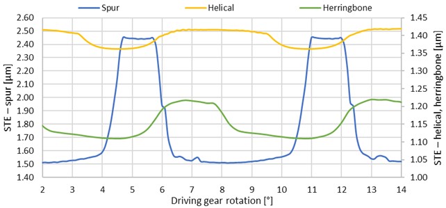
In terms of peak-to-peak transmission error (see Table 2), spur gearing shows a significantly higher value than other types, e.g., almost 16 times higher than helical gearing. The herringbone PTP-STE value is twice as high as the helical one due to a lower (half) overlap ratio. Real contact ratios are higher than the theoretical ones due to teeth deformation in the mesh. Approximately, by 4.8 % (0.5°) and 2.5 % (0.3°) for spur and helical/herringbone gears, respectively.
Table 2STE values for different variants and types of gears
STE [μm] | ||||||||||||
Variant | Spur | Helical | Double helical | Herringbone | ||||||||
Min | Max | PTP | Min | Max | PTP | Min | Max | PTP | Min | Max | PTP | |
I | 1.51 | 2.45 | 0.94 | 1.36 | 1.42 | 0.06 | 1.89 | 2.01 | 0.12 | 1.11 | 1.22 | 0.11 |
II | 8.32 | 9.50 | 1.18 | 8.58 | 8.69 | 0.11 | 8.84 | 9.05 | 0.21 | 7.80 | 7.97 | 0.17 |
III | 25.7 | 27.5 | 1.86 | 25.7 | 26.1 | 0.37 | 26.7 | 27.2 | 0.47 | 24.9 | 25.3 | 0.43 |
Fig. 9Contact pressure for variant I at driving gear angular displacement of 4°: a) spur, b) helical, c) double helical, d) herringbone gears
Comparing herringbone and double helical gears (see Fig. 10 and Table 2), the peak-to-peak values reach the same values. However, the mean value of the double helical gears’ transmission error is higher than at herringbone gears since there is lower stiffness due to no interaction between the left and right halves. It can also be seen at the increased stress and its distribution in driven gear tooth roots as shown in Fig. 11.
Fig. 10Comparison of herringbone and double helical gears STE graphs
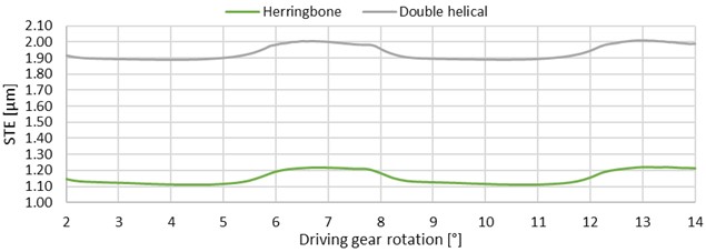
Fig. 11Equivalent stress (von-Mises) in driven gear tooth roots at driving gear angular displacement of 4°: a) spur, b) helical, c) double helical, d) herringbone gears
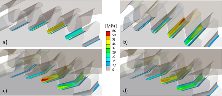
The maximum equivalent stress (von-Mises) in the tooth roots of the double helical driven gear is by 13.2 % higher than in the herringbone one. However, the maximum equivalent stress of the driving gear is slightly higher in the case of herringbone gears (at the same angular position). The maximum root stress at the spur gear, for this position, is lower (58 MPa) as the load is distributed between the two pairs in the mesh. In the single-pair engagement, the stress increases up to 93 MPa. In all cases, the maximum stress is in the root where compression occurs.
Based on the results of the stress-strain analysis and the static transmission error of the variant I, the parameters of the long tip relief modification (see Table 3) were determined for each type of gearing separately. The resulting waveforms (see Fig. 12) and STE values (see Table 4) show a reduction in fluctuations of the transmission error for all cases. Specifically, reduction of peak-to-peak values by 80.9, 50, 25, and 45.5 % for spur, helical, double helical, and herringbone gears, respectively. On the other hand, mean values of the transmission error increased in all cases. This can also be observed at higher maximum root stress. Moreover, in contrast to the transmission error, the fluctuation of the maximum root stress increased. The contact ratios decreased but were still slightly higher than the theoretical ones due to the deformation.
Fig. 12Graphs of STE for unmodified and modified types of gears – variant I
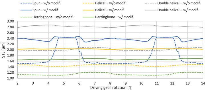
Table 3Parameters of the linear tip relief modifications
Spur | Helical | Double helical | Herringbone | |
Amount [µm] | 1.77 | 1.41 | 1.95 | 1.15 |
Starting diameter [mm] | 41.45/57.29 | 41.14/57.00 | ||
In the starting/default position, in contrast to the unmodified gearing, the middle tooth pair was not in contact due to the lack of material at the modification area. After the load was applied, the gap between the flanks was closed and the teeth just touched without excessive increased contact pressure caused by a corner contact. However, at the double helical gearing, the gap was not completely closed which probably led to the lower decrease in the peak-to-peak value (only by 25 %) compared to the other types of gears.
Table 4STE values for unmodified and modified types of gears – variant I
STE [μm] | ||||||||||||
Modification | Spur | Helical | Double helical | Herringbone | ||||||||
Min | Max | PTP | Min | Max | PTP | Min | Max | PTP | Min | Max | PTP | |
w/o | 1.51 | 2.45 | 0.94 | 1.36 | 1.42 | 0.06 | 1.89 | 2.01 | 0.12 | 1.11 | 1.22 | 0.11 |
w/ | 2.29 | 2.47 | 0.18 | 2.02 | 2.05 | 0.03 | 2.77 | 2.87 | 0.09 | 1.65 | 1.71 | 0.06 |
By adding the shafts and changing boundary conditions (variant II), the average values of the transmission error for all gear types increased significantly. However, the increase in peak-to-peak values was less notable (see Table 2). Percentagewise, helical gearing was the most affected one – almost twice as much. Curves of the static transmission error are shown in Fig. 13.
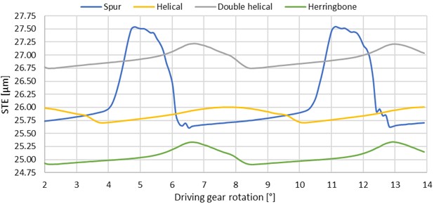
By changing the boundary conditions – allowing all rotational degrees of freedom at the ends of the shafts (variant III), a further increase in the transmission error was noted. The increase in peak-to-peak values was even more pronounced in this case (see Table 2). STE curves (see Fig. 14) are similar to those of the variant II. In both cases, the load caused shaft torsion, resulting in the end of the driving shaft, where the rotation was evaluated, being 0.08 degrees behind the opposite end, where the angular displacement was defined.
Fig. 13Graphs of STE – variant II
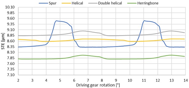
Fig. 14Graphs of STE – variant III
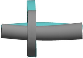
Deformation of the shafts (see Fig. 15) caused the gears to deflect from their ideal position, therefore incorrect meshing. This effect was much more significant for the variant III. For both cases, the contact pressure distribution (see Fig. 16) became uneven – pressure, and contact area increased on the side closer to the end of the shaft (increase of the contact ratio). At the variant III, there was even a partial loss of contact on the opposite side (reduction of the contact ratio). In addition, the difference between double helical and herringbone gears can be observed. At herringbone gearing, both helices are more loaded on one side (closer to the end of the shaft), whereas at double helical gearing, only the helix that is closer to the end of the shaft.
Fig. 15Spur gear-shaft system deformation (200 times magnified)
a) Variant II
b) Variant III
However, it should be noted that no contact was set between the left and right halves of the double helical gear. These parts could theoretically interfere each other in the axial direction due to the mesh forces. This was happening at the driving gear, while the driven halves were being separated from each other. The interference in the axial direction was in the order of microns. In a technical experiment, there would have to be a gap between the halves corresponding to this interference to prevent the contact. Otherwise, the impact on the results must be investigated as well.
Fig. 16Contact pressure for variant II and III of all gear types at driving gear angular displacement of 4°
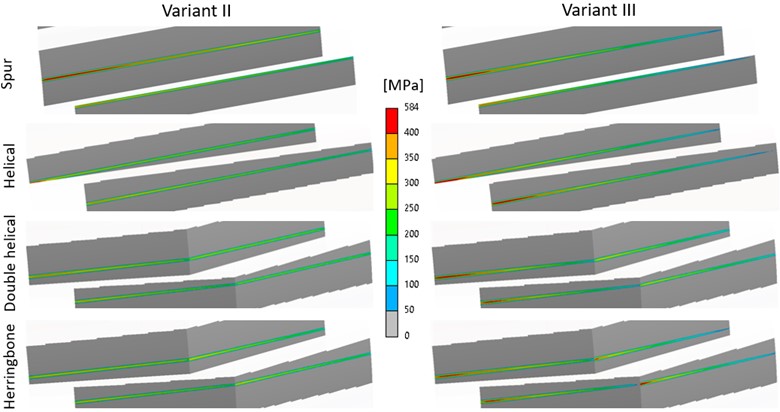
Regarding the root stress, it was also significantly affected compared to the variant I (see Fig. 17). In general, due to the deformation of the shafts, the increased stress was concentrated on the side of the nearer end of the shaft, as in the case of the contact pressure, and the maximum values rose as well. The maximum root stress appeared at the variant III at the helical gear (104 MPa), followed by double helical (101 MPa), spur (95 MPa) and finally herringbone gearing (92 MPa). On the other hand, the variant II had the highest impact on root stress of the double helical gear (81 MPa). The fluctuation of the maximum stress also increased, similarly to the case of the modified gearing.
Fig. 17Equivalent stress (von-Mises) in driven gear middle tooth root at driving gear angular displacement of 4°: a) spur, b) helical, c) double helical, d) herringbone gear
5. Conclusions
In this case study, static contact analyses, based on FEM, in Ansys Workbench software were conducted to determine static transmission error, contact pattern and pressure, and tooth root stress of spur, helical, double helical, and herringbone gears. Influence of three different variants of boundary conditions were investigated. Namely, sole gears constrained in their centers with only rotation about the axes allowed, gears with shafts constrained at the location of theoretical bearings with only rotation about the axes allowed and with all rotational DOFs allowed. There was a variant with micro-geometric modification tip relief in the case of sole gears without shafts as well. The main results can be concluded as follows:
– Moderate increase in mean and peak-to-peak values of STE; and uneven load distribution along gear width by adding shaft flexibility and significant increase in mean and peak-to-peak values of STE; and more uneven load distribution by allowing all rotational DOFs of shaft ends.
– Marked difference between the double helical and herringbone gears in terms of mean values of STE, contact pressure and tooth root stress across all variants.
– Higher peak-to-peak STE values of the herringbone-like gears compared to the helical ones due to half overlap ratio at the same parameters.
– Most pronounced decrease in STE fluctuations by introducing the long tip relief modification in case of the spur gears.
– Lower positive effect of the modification at the double helical gears than herringbone ones.
In the future work, the analyses will be extended by different values of loading torque in order to make the conclusions more general. The model will be improved by tooth flank modifications and bearing stiffnesses and their effects on the transmission error and gear mesh stiffness will be examined comprehensively. The compact test rig, presented in this paper, will be constructed as well as the studied gears will be made, and the transmission error will be measured and compared with the results obtained by the numerical simulations.
References
-
A. Palermo, L. Britte, K. Janssens, D. Mundo, and W. Desmet, “The measurement of Gear Transmission Error as an NVH indicator: Theoretical discussion and industrial application via low-cost digital encoders to an all-electric vehicle gearbox,” Mechanical Systems and Signal Processing, Vol. 110, pp. 368–389, Sep. 2018, https://doi.org/10.1016/j.ymssp.2018.03.005
-
Y. Benaïcha, J. Perret-Liaudet, J.-D. Beley, E. Rigaud, and F. Thouverez, “On a flexible multibody modelling approach using FE-based contact formulation for describing gear transmission error,” Mechanism and Machine Theory, Vol. 167, p. 104505, Jan. 2022, https://doi.org/10.1016/j.mechmachtheory.2021.104505
-
A. Fernández-Del-Rincón, M. Iglesias, A. De-Juan, A. Diez-Ibarbia, P. García, and F. Viadero, “Gear transmission dynamics: Effects of index and run out errors,” Applied Acoustics, Vol. 108, pp. 63–83, Jul. 2016, https://doi.org/10.1016/j.apacoust.2015.11.012
-
C. Liu, W. Shi, and K. Liu, “Calculation method of mesh stiffness for helical gear pair with manufacturing errors, assembly errors and tooth modifications,” Meccanica, Vol. 57, No. 3, pp. 541–565, Mar. 2022, https://doi.org/10.1007/s11012-022-01479-8
-
Z. Zhao, Y. Yang, H. Ma, H. Wang, H. Tian, and C. Han, “Meshing characteristics of spur gear pairs with tooth modification under different assembly errors and sensitivity analysis for impact factors,” Journal of Mechanical Science and Technology, Vol. 37, No. 1, pp. 149–162, Jan. 2023, https://doi.org/10.1007/s12206-022-1215-2
-
X. Liang, H. Zhang, L. Liu, and M. J. Zuo, “The influence of tooth pitting on the mesh stiffness of a pair of external spur gears,” Mechanism and Machine Theory, Vol. 106, pp. 1–15, Dec. 2016, https://doi.org/10.1016/j.mechmachtheory.2016.08.005
-
Z. Li, H. Ma, M. Feng, Y. Zhu, and B. Wen, “Meshing characteristics of spur gear pair under different crack types,” Engineering Failure Analysis, Vol. 80, pp. 123–140, Oct. 2017, https://doi.org/10.1016/j.engfailanal.2017.06.012
-
Z. Y. Chin, W. A. Smith, P. Borghesani, R. B. Randall, and Z. Peng, “Absolute transmission error: A simple new tool for assessing gear wear,” Mechanical Systems and Signal Processing, Vol. 146, p. 107070, Jan. 2021, https://doi.org/10.1016/j.ymssp.2020.107070
-
Z.-G. Wang and Y.-C. Chen, “Design of a helical gear set with adequate linear tip-relief leading to improved static and dynamic characteristics,” Mechanism and Machine Theory, Vol. 147, p. 103742, May 2020, https://doi.org/10.1016/j.mechmachtheory.2019.103742
-
H. Zou, S. Wang, F. Li, L. Liu, L. Li, and Z. Li, “Improved algorithm of tooth surface topological modification and nonlinear dynamic analysis of herringbone gears,” Mechanism and Machine Theory, Vol. 180, p. 105151, Feb. 2023, https://doi.org/10.1016/j.mechmachtheory.2022.105151
-
T. Lin and Z. He, “Analytical method for coupled transmission error of helical gear system with machining errors, assembly errors and tooth modifications,” Mechanical Systems and Signal Processing, Vol. 91, pp. 167–182, Jul. 2017, https://doi.org/10.1016/j.ymssp.2017.01.005
-
D. Bartosova, V. Otipka, and K. Rehak, “Determination of transmission error in spur gear by numerical approach,” Vibroengineering Procedia, Vol. 19, pp. 284–288, Sep. 2018, https://doi.org/10.21595/vp.2018.20239
-
Z. Fraňová, K. Řehák, and A. Prokop, “Transmission error of the spiral bevel gears,” in Engineering Mechanics, pp. 138–141, 2020, https://doi.org/10.21495/5896-3-138
-
J. Yang, T. Lin, Z. He, and M. Chen, “Novel calculation method for dynamic excitation of modified double-helical gear transmission,” Mechanism and Machine Theory, Vol. 167, p. 104467, Jan. 2022, https://doi.org/10.1016/j.mechmachtheory.2021.104467
-
J.-W. Liu, J.-P. Liu, X.-B. Shu, A. Mikkola, and G.-X. Ren, “An efficient multibody dynamic model of three-dimensional meshing contacts in helical gear-shaft system and its solution,” Mechanism and Machine Theory, Vol. 142, p. 103607, Dec. 2019, https://doi.org/10.1016/j.mechmachtheory.2019.103607
-
X. Zhao, W. Fan, Z. Wang, Z. Wen, and P. Wang, “An explicit finite element approach for simulations of transient meshing contact of gear pairs and the resulting wear,” Wear, Vol. 523, p. 204802, Jun. 2023, https://doi.org/10.1016/j.wear.2023.204802
-
S.-Y. Ye and S.-J. Tsai, “A computerized method for loaded tooth contact analysis of high-contact-ratio spur gears with or without flank modification considering tip corner contact and shaft misalignment,” Mechanism and Machine Theory, Vol. 97, pp. 190–214, Mar. 2016, https://doi.org/10.1016/j.mechmachtheory.2015.11.008
-
T. Duan, J. Wei, A. Zhang, Z. Xu, and T. C. Lim, “Transmission error investigation of gearbox using rigid-flexible coupling dynamic model: Theoretical analysis and experiments,” Mechanism and Machine Theory, Vol. 157, p. 104213, Mar. 2021, https://doi.org/10.1016/j.mechmachtheory.2020.104213
-
Z. Liu et al., “Dynamic characteristics of spur gear system with tooth root crack considering gearbox flexibility,” Mechanical Systems and Signal Processing, Vol. 208, p. 110966, Feb. 2024, https://doi.org/10.1016/j.ymssp.2023.110966
-
B. Yuan, G. Liu, Y. Yue, L. Liu, and Y. Shen, “A novel tooth surface modification methodology for wide-faced double-helical gear pairs,” Mechanism and Machine Theory, Vol. 160, p. 104299, Jun. 2021, https://doi.org/10.1016/j.mechmachtheory.2021.104299
-
C. Liu, Z. Fang, and F. Wang, “An improved model for dynamic analysis of a double-helical gear reduction unit by hybrid user-defined elements: Experimental and numerical validation,” Mechanism and Machine Theory, Vol. 127, pp. 96–111, Sep. 2018, https://doi.org/10.1016/j.mechmachtheory.2018.04.022
-
P. Kučera, V. Píštěk, A. Prokop, and K. Řehák, “Transmission error analysis for heavy-duty gearbox,” Vibroengineering PROCEDIA, Vol. 18, pp. 113–116, May 2018, https://doi.org/10.21595/vp.2018.19919
-
S. L. Harris, “Dynamic Loads on the Teeth of Spur Gears,” Proceedings of the Institution of Mechanical Engineers, Vol. 172, No. 1, pp. 87–112, Jun. 1958, https://doi.org/10.1243/pime_proc_1958_172_017_02
-
R. W. Gregory, S. L. Harris, and R. G. Munro, “Dynamic behaviour of spur gears,” Proceedings of the Institution of Mechanical Engineers, Vol. 178, No. 1, pp. 207–218, Jun. 1963, https://doi.org/10.1177/002034836317800130
-
S. P. Radzevich, “Gear Noise and Vibration,” in Theory of Gearing, Boca Raton: CRC Press, 2022, pp. 889–908, https://doi.org/10.1201/9781003311744-37
-
W. Guangjian, C. Lin, Y. Li, and Z. Shuaidong, “Research on the dynamic transmission error of a spur gear pair with eccentricities by finite element method,” Mechanism and Machine Theory, Vol. 109, pp. 1–13, Mar. 2017, https://doi.org/10.1016/j.mechmachtheory.2016.11.006
-
M. Abruzzo, M. Beghini, C. Santus, and F. Presicce, “A dynamic model combining the average and the local meshing stiffnesses and based on the static transmission error for spur gears with profile modification,” Mechanism and Machine Theory, Vol. 180, p. 105139, Feb. 2023, https://doi.org/10.1016/j.mechmachtheory.2022.105139
-
D. Palmer and M. Fish, “Evaluation of Methods for Calculating Effects of Tip Relief on Transmission Error, Noise and Stress in Loaded Spur Gears,” GearTechnology, pp. 56–67, 2012.
-
A. Czakó, K. Řehák, A. Prokop, and V. Ranjan, “Determination of static transmission error of helical gears using finite element analysis,” Journal of Measurements in Engineering, Vol. 8, No. 4, pp. 167–181, Dec. 2020, https://doi.org/10.21595/jme.2020.21825
-
J. Zhan, M. Fard, and R. Jazar, “A CAD-FEM-QSA integration technique for determining the time-varying meshing stiffness of gear pairs,” Measurement, Vol. 100, pp. 139–149, Mar. 2017, https://doi.org/10.1016/j.measurement.2016.12.056
About this article

The research that led to these results was funded by the FSI Science Fund project at Brno University of Technology, reg. no. FV22-02.
The datasets generated during and/or analyzed during the current study are available from the corresponding author on reasonable request.
Alexander Czakó: conceptualization, formal analysis, investigation, methodology, visualization, writing – original draft preparation. Kamil Řehák: supervision, writing – review and editing, resources. Aleš Prokop: conceptualization, writing – review and editing. Jakub Rekem: visualization, writing – original draft preparation. Daniel Láštic: writing – original draft preparation, methodology, investigation. Miroslav Trochta: conceptualization, writing – review and editing.
The authors declare that they have no conflict of interest.
