Abstract
As an atypical conventional gear pair, non-circular gear has a variable transmission ratio, which can be used to improve the structure and transmission characteristics in some applications, such as variable speed grinding mechanism, wool blending machine guide mechanism, continuously variable transmission structure and so on. According to the friction theory of conjugate surfaces, the transmission characteristics will be affected by the micro topography of tooth surface, but the shaped tooth surface of non-circular gear with normal hobbing method is not uniform, because of its variable radius and flank orientations of tooth surface. The research on the relationship between micro topography and parameters of non-circular gear is necessary, thus an improved manufacturing method with ultrasonic-assisted motion was presented in this paper, the mathematical equations for the theoretical tooth surface of non-circular gear with and without ultrasonic-assisted motion have been derived in this paper, also the equations for cutting parameters (step displacement, step rotating angle) have been proposed, shown that all the parameters (initial parameters of gear and gear hob, cutting parameters in manufacturing process) will affect the formed micro surfaces. In detail, the height and width of micro undulating tooth surface periodically increase and decrease, getting the maximum value at , where is the maximum radius. The height and width of micro tooth surface will increase with any control parameter increase, the height of most micro peaks is near 6.5um in normal hobbing process. While, the tooth surface with ultrasonic-assisted motion is more regular and clearer with the maximum height decrease from 6.5 um to 2.7 um, getting more compact cutting tracks and lower surface roughness. The experimental results shows that ultrasonic-assisted hobbing has obviously positive influence for micro tooth surface, provides the theoretical support for a further analysis and better application of unconventional gear pair.
1. Introduction
As a gear drive with variable transmission characteristics, non-circular gear is different from conventional ones in tooth profiles and pitch curves, so the geometric, transmission and load characteristics of unconventional gear forms are variable with different transmission functions [1].
Based on the meshing theory of conjugate surface, many scholars did the analysis and optimization for the characteristics of different gear drives. Tang focused on the tooth contact analysis of bevel gear with SGM method revealed the influence properties of different errors (misalignment, fabrication offsets) on the contact results of gear pair [2, 3]. Wang and Sun focused on the computerized research and simulation of epicycloids hypoid gear, proposing the characteristics of contact area and transmission errors, found the epicycloid tooth profile can improve the sensitivity of errors [4, 5]. Taken the relative sliding friction of meshed tooth surface into consideration, the improved contact analysis of spiral bevel gears was made by Tian [6]. F. L. Litvin and Fan presented the shaving computation methods for both spur and helical gears, revealed the trend of contact ellipse for different gear types [7]. The common manufacturing methods for conventional gear types are based on the generating motion of conjugate surface with constant hobbing parameters, the discrete processing traces on target tooth surfaces are even and the roughness is uniform. However, non-circular gear usually rotates with variable radius, causing irregular cutting steps, processes traces and mutative roughness, the conventional machining methods with constant cutting parameters cannot be directly applied on non-circular gears for uniform micro surface.
In order to reduce roughness, improve cutting force and surface precision, a compound generating method with ultrasonic-assisted motion was presented. Yin and Zhao discussed the process of surface grinding with ultrasonic-assisted motion or not, and established a mathematical model for the prediction of grinding force and surface quality [8-10]. Venkatesh considered the surface finishing of bevel gear, presented a finite element simulation for bevel gear with different input parameters [11]. Harpreet proved that the average and maximum surface roughness of bevel gear could be improved to 91.04 % and 71.98 % in an experiment on bevel gear with AISI 1040 carbon steel [12]. Wei and Yang focused on the surface lapping with ultrasonic-assisted motion, found that the material removal rate of ultrasonic lapping is much higher and the surface quality is much better than conventional lapping method [13, 14]. Su investigated the SEM topography of two different Ti6Al4V with the method of conventional milling and ultrasonic-assisted milling, shows the SEM surface roughness can be reduced up to 23.3 % and 19.1 % with UAM method than CM method, and indicates the positive influence of UAM method on surface roughness [15]. An focused on the material removal mechanism of FRCMCs-SiC in machining processes, discussed the influence of process parameters on the machined surface quality, proved that ultrasonic-assisted machining method can reduce cutting force and tool wear, improve machining quality and efficiency [16]. In addition, the experimental turning performance of ultrasonic-assisted turning with textured cutting insert was carried out by Sofuoglu, revealed the reason for the 35.89 % improvement during ultrasonic-assisted turning as compared to conventional turning [17]. Liu analyzed the wear state of tool in ultrasonic-assisted milling and conventional milling, found that the burr produced by ultrasonic-assisted milling was not obvious and the curl angle of chip generated from ultrasonic-assisted milling was smaller than that from conventional milling in the same wear time, and better surface roughness with lower cutting force and temperature [18]. Due to the benefits of ultrasonic-assisted machining, Amini designed an elliptical ultrasonic-assisted turning model, the better surface finish and lower cutting forces on the turning process of copper with elliptical ultrasonic-assisted motion has been verified by experiment [19].
These results confirmed that the new generating methods with ultrasonic-assisted motion could improve tooth surface roughness obviously. But the basic parameters of non-circular gear are complex and should be derived for surface hobbing with ultrasonic-assisted motion.
Figliolini established the base curve of non-circular gear by the Aronhold theorem, derived the constant pressure angle of this kind of non-circular gear pair [20]. Furthermore, the mathematical model, transmission principle and theoretical simulation model of non-circular gear was presented by F. Y. Zheng et al. [21]. Fuentes proposed two different methods for shaped teeth by face-milling cutters, and analyzed the advantages and disadvantages of the proposed two versions by numerical examples [22].
The above results demonstrate that ultrasonic-assisted processing method is better for surface roughness than normal cutting method, and the specific parameters of non-circular gear can be derived.
This paper compared the two forming methods of non-circular gear with or without ultrasonic-assisted motion, including the mathematical equations of theoretical surface, incremental offset distance and rotating angle of step, micro height and grooves of adjacent cutting points with different parameters. Also, the discussion of the relationship between finished surfaces and cutting methods is covered in this paper. The results provide the theoretical support for further analysis and application of unconventional gear type with complex tooth surface.
2. Surface Hobbing of non-circular gear
2.1. Tooth surface profile of normal gear
With the development and application of gear pair, various processing methods, such as milling, hobbing and so on, have been applied. Based on the simulation processing method proposed by F. L. Litvin [1], the surface hobbing process of normal cylindrical gear can be shown as Fig. 1.
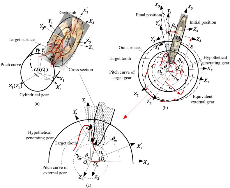
Fig. 1 shows the conjugate generating process of tooth surface. -, - and are fixed coordinates on cylindrical gear, hypothetical generating gear and gear hob respectively. -, - and - are movable coordinates on cylindrical gear, hypothetical generating gear and gear hob respectively. is the rotating angle of movable coordinate - with different meshing point. In Fig. 1(b), keeps a constant distance away from with a distance . In the generating process of tooth surface of cylindrical gear, the gear hob is coupled rotating around and , the tooth flank of gear hob is always the same with tooth flank of hypothetical generating gear (inner gear) and equivalent external gear at point with coordinate transformation by - to -. The mathematical equation for tooth profile at point of gear hob can be derived by the tooth profile of hypothetical inner gear or equivalent external gear, shown as:
where is the common contact point on gear hob, equivalent external gear and hypothetical generating gear, is the starting angle of tooth profile , is the range of tooth profile angle, is the basic radius.
According to the pure rolling engagement of those three tooth profiles and conversion matrix of the coordinate - to the coordinate -, the tooth profile of target gear can be proposed as:
Eq. (3) illustrates the mathematical equation for target gear, and are the translation distance of movable coordinate - with meshing from (rotating angle of cylindrical gear is ) to (rotating angle of cylindrical gear is ). As described in Fig. 2(b), gear hob always keeps the distance away from , so and can be expressed by the component of arc length in the or directions. Compared with Eq. (2), Eq. (3) has the same form for tooth profile, the target gear is cylindrical gear with the constant radius .
Fig. 1Theoretical presentation of normal cylindrical gear
2.2. Surface equation of non-circular gear
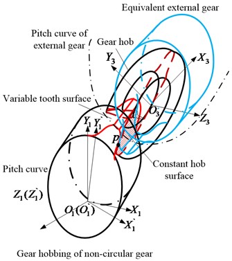
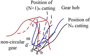
Based on the conventional Hobbing method of normal cylindrical gear with constant cutting steps, the simulation manufacturing process for non-circular gear tooth profile has been arranged as shown in Fig. 2.
Fig. 2Simulated hobbing of non-circular gear with conventional method
a)
b)
As shown in Fig. 2(b), the generating profile of gear hob is overlapped with the tooth profile of hypothetical external gear at point . During the generating process of non-circular gear, the radius of non-circular gear is angle-varying, related parameters , , can be derived by external gear rolling on the pitch curve of non-circular gear as:
The coordinate transformation matrix from - to - can be established as:
Matrix is the coordinate transformation from - to - and can be established as:
In Fig. 2(b), non-circular gear is rotating clockwise while the gear hob is rotating counter-clockwise so the tooth surface of non-circular gear can be proposed as , and the responded rotating angle and translation displacements of gear hob can be established as:
Taken the parameters of gear hob in Table 1 into Eq. (7), the responded displacement and rotating angle of equivalent external gear with rotating angle or of non-circular gear are calculated by MATLAB, illustrated as Fig. 3.
Table 1Some parameters of gear hob
Parameter | Value |
Equivalent modulus (mm) | 2 |
Number of tooth of equivalent external gear | 12 |
Order of non-circular gear | 1 |
Distance (mm) | 34 |
Pressure angle of gear hob () | 20 |
Fig. 3Displacement Dh and rotating angle θh of equivalent external gear
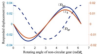
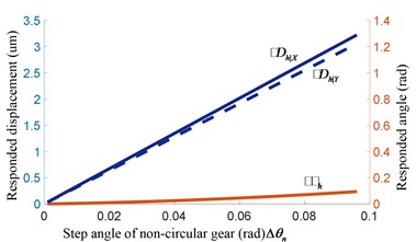
a) Incremental displacement and angle
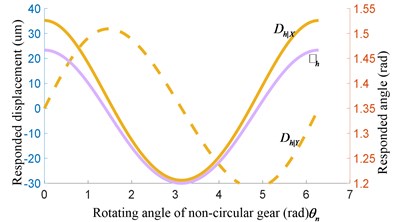
b) Responsible displacement and angle
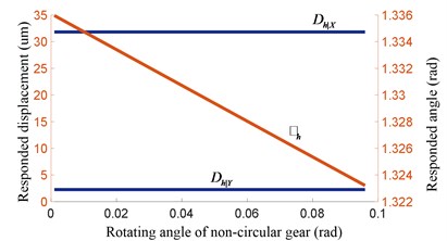
c) Incremental displacement and angle
d) Responsible displacement and angle
In Fig. 3(a) and (b), the parameters of gear hob and step value are constant, while the value of translation parameters , , and step increment , , are variable. In addition, with hobbing goes from short axis to long axis of non-circular gear, the change trend of , , and , , are the same with radius of non-circular gear, as Eq. (3). The radius increases from short axis to long axis, the step increment of gear hob will increase with difference growth. Also, the change of translation parameters , , will follow the regular pattern of axis. Additionally, , are range from –0.03 to 0.03 mm and the value of is about 0.018 rad with 0.001 rad. Fig. 3(c) and (d) are values of step parameters with 0.01 rad, demonstrate , , and , , are also varying periodically, the lager step value , the lager step parameters , , and , , .
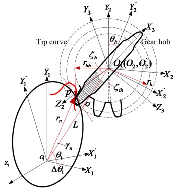
2.3. Surface Hobbing ultrasonic -assisted motion
As shown in Eq. (6) and Fig. 3, the surface roughness and accuracy of non-circular gear are different with different angle , even the step angle is controlled constant or step increment, and are obtained accurately. The transmission performance (transmission error, noise, vibration and so on) is limited by surface roughness and accuracy. So the processing method should be improved, taken the range of step increment , and amplitude of ultrasonic-assisted processing method into consideration, ultrasonic-assisted processing will improve the step increment , to a certain degree. The manufacturing model with elliptical ultrasonic-assisted method is set up, shown as Fig. 4.
Fig. 4Ultrasonic-assisted hobbing of non-circular gear
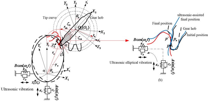
Fig. 3 shows the step distance of any adjacent two hobbing points on tooth surface ranges from 0.0315 mm to 0.0355 mm with different , which will cause machining accuracy unstable by influencing the feed of gear cutter. In order to ensure surface accuracy constant as much as possible, a compound cutting method with ultrasonic-assisted movement are presented. The ultrasonic motion of non-circular gear is established as an elliptical motion with at the direction and at the direction, shown as Fig. 4.
Ultrasonic-assisted motion of gear hob is an elliptical-like ultrasonic vibration with ultra-high frequency. Coupled with the relative rotation and movement between hob and non-circular gear, the trajectory of cutting point on tooth surface is actually compound motion. Compared with the rotation and movement of gear hob, the period of elliptical ultrasonic motion is extremely short, and the amplitude is small. It will not change the contact relationship between gear hob and target non-circular gear within a large range, but will improve the step distance as Fig. 4(b). While the high-frequency separation between hob and non-circular gear be ignored, the ultrasonic-assisted responded rotating angle and translation displacements are obtained as:
where 0.005 mm, 0.004 mm, is the rotating angle of non-circular gear with ultrasonic-assisted method, is the step angle of non-circular gear and , is the angular velocity of non-circular gear.
3. Micro tooth surface analysis of non-circular gear
3.1. Micro peak and groove on shaped surface
Compared Eq. (7) and Eq. (8), the responded rotating angle , translation displacements and are affected by added ultrasonic motion. With the expansion and simplification of Eq. (7), the ultrasonic-assisted values and can be considered as Eq. (7) attached with some extra high frequency and small amplitude expressions.
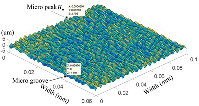
In the normal forming process, the tooth profile of non-circular gear is created by material removal. Different amount and spacing of removed material make different surface quality as shown in Fig. 5.
Fig. 5Micro surface of shaped tooth profile
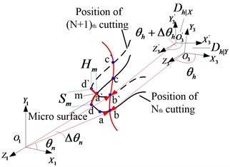
As shown in Fig. 5, the unsmooth surface is caused by the retained material between two adjacent cutting steps th and th on non-circular gear blank, making undulating continuous tooth surface as or in Fig. 5(b) and (c). Based on the translation displacements Eq. (8), the upper cutting point , which is shown as micro peak in Fig. 5(c), at th cutting position can be derived as:
The mathematical expression for the other three points can be derived by , and the area depits the material removed at the initial position with angle . With the same method, the cutting area with rotating angle at )th cutting point can be built, so the remained material between and is the unsmooth tooth surface for hobbing step increases fromth to )th. The value of micro peak and spacing of micro remained material can be derived as follows:
is equation for the tip radius of gear hob and , is equivalent modulus of non-circular gear, is obtained as an equation for a tooth profile at point on non-circular gear. As a common point between arcs and , the two mathematical expressions for cutting point should be consistent with each other:
With the solution of Eq. (11), the phase angle of on hypothetical equivalent external gear can be established by , , and . Similarly, the micro groove can be built by the tooth tip point of gear hob.
3.2. Micro tooth surface with different parameters
As shown in Fig. 5 and Eq. (12), the height of micro peaks, spacing between micro grooves are related to some primary parameters, such as radius , of gear hob, starting angle of tooth profile, step length , radius and so on. Taken the processing parameters of gear hob and non-circular gear into Eq. (12), the microscopic micro tooth surface is shown in Fig. 6.
Fig. 6 contains the comparison of micro tooth surface with different methods. Compared Fig. 6(a) and (b), it can be seen that the tooth surface with ultrasonic-assisted vibration is more regular, the height of micro peak also decreases from 6.5 um to 2.7 um with much smaller spacing, making surface roughness much lower. The further variation of micro peak and spacing with different parameters are shown in Fig. 7.
As indicated in Fig. 6, the microfeatures of generated tooth surface can be reflected by the height and width of machining tracks, named as micro peak and spacing in this paper. Fig. 7(a)-(d) illustrate the trend of micro peak and spacing with different parameters.
Fig. 6Micro tooth surface with different methods
a) Micro surface without ultrasonic-assisted motion
b) Micro surface involved with ultrasonic-assisted motion
Fig. 7Micro surface with different control parameters
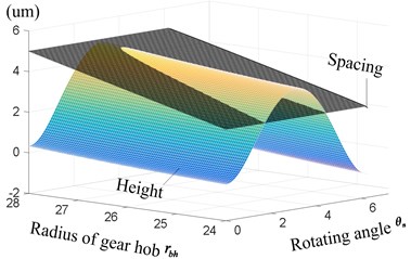
a) Height and spacing with different radius
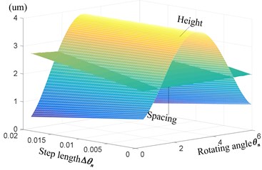
b) Height and spacing with different step length
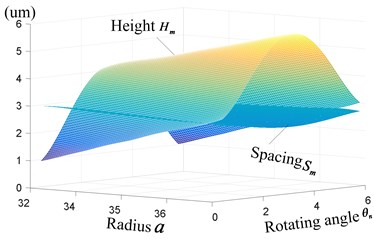
c) Height and spacing with different radius
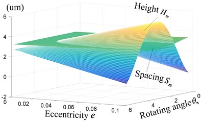
d) Height and spacing with different eccentricity
According to the conjugate generating process in Eq. (11) and Fig. 5, spacing and height are primarily determined by the distance and depth of two adjacent cutting positions. Because of the variable transmission ratio between non-circular gear and equivalent generating gear with variable radius, the constant step angle and depth of equivalent generating gear will engender variable and , causing changeable spacing and micro peak .
As shown in Eq. (2), the step distance of two adjacent cutting positions on gear hob can be established as , showing the same trend with radius , while the modulus and tooth number of gear is series values not arbitrary, so the height and thickness of tooth will change with different . Taken these decrease parameters into Eq. (12), the height and spacing decrease, too. In addition, is not only influenced by the step distance , but also the cutting depth of gear hob and non-circular gear, the thickness of tooth profile, the spacing is merely affected by the step distance, so the change of is more pronounced than it of height with different radius . Based on Eq. (4), with angle ranges from 0 to , radius increases first and then decreases, so the height on the tooth surface of non-circular gear should be added by the additional values of variable radius with much obvious range than spacing at the direction of rotating angle in Fig. 7(a).
The changeable height and spacing create different micro topography on generated tooth surface. mainly influence the height of peaks and spacing influence both the spacing and smoothness of peaks, with radius decrease from 28 mm to 24 mm, the range of changes from –3.04 um-4.96 um to –1.81 um-2.71 um and the spacing of peaks decrease from 5 um to 3 um, causing more regular, compact and obvious peaks. Also, the average error of peaks is improved from 0.96 um to 0.45 um, which shows much better regularity and accuracy to the theoretical tooth surface.
Fig. 7(c)-(d) illustrate the further properties of height and width with different parameters: step length , radius parameter and eccentricity of non-circular gear, getting the similar trend as Fig. 7(a). With the decrease of step length , eccentricityand parameter , the range of height and spacing decrease with positive correlation. Combined Eq. (12) and Fig. 6-7, it can be seen that the micro topography of tooth surface is mainly affected by the spacing of adjacent cutting tracks and height of cutting peaks, these tracks and peaks are determined by the conjugate relationship between gear hob and non-circular gear, the tooth profile of gear hob, step angle and so on. With the decrease of radius , step angle , eccentricity and parameter , the height and spacing decrease, also the average generating error decrease with more regular, compact and clear surface. So the micro topography of non-circular gear is variable and determined by any change of these parameters, showing the relationship between the trend of parameters and micro topography in appendix Table A1.
4. Experiment
For a better understanding and verification of theoretical micro tooth surface of non-circular gear, the experimental hobbing of non-circular gear is operated with cutting parameters in Table 2 and control parameters of non-circular gear in Table 3 with 17Cr2Ni2Mo.
Table 2Ultrasonic vibration parameters of gear cutter
Parameter | Value |
Amplitude (um) | 5 |
Amplitude (um) | 4 |
Frequency (KHz) | 20 |
spindle speed (r/min) | 110 |
Axial feed speed (mm/r) | 0.16 |
cutting depth (mm/r) | 0.05 |
Table 3Parameters of non-circular gear
Parameter | Value |
Radius factor (mm) | 16 |
Eccentricity | 0.1 |
Orders | 1 |
Rotating speed (r/min) | 0.2 |
Modules (mm) | 2 |
Table 4Property parameters of 17Cr2Ni2Mo
Parameter | Value |
Density (kg/m3) | 8000 |
Tensile strength (MPa) | ≥ 1200 |
Hardness (HB) | ≤ 269 |
Poisson’s ratio | 0.30 |
Yield strength (MPa) | ≥ 1080 |
Thermal conductivity (W m/K) | 16.3 |
As alloy steel with high property parameters, 17Cr2Ni2Mo is often used on gear transmission parts. So this paper focused on the micro surface topography of non-circular gear with two different cutting methods when machining 17Cr2Ni2Mo under these parameters in Tables 2 to 4.
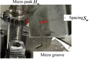
Fig. 8Experimental tooth surfaces with two methods
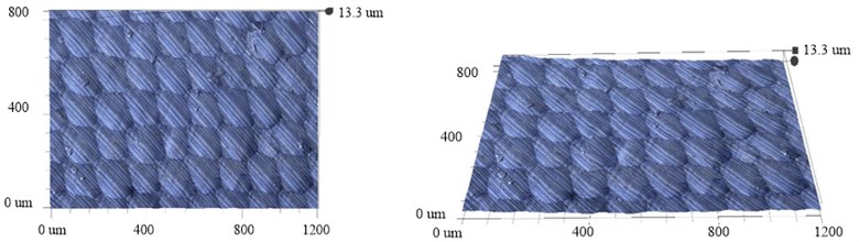
a) Tooth surfaces made by conventional method
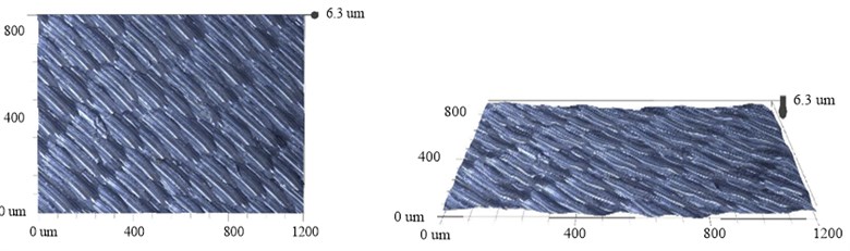
b) Tooth surfaces made by ultrasonic-assisted method
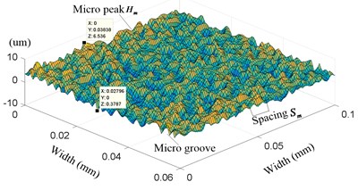
Fig. 8 shows the micro surface of non-circular gear, which were photographed by the Super depth of field 3D microscopy system (VHX-1000C/VW-6000). Comparing the two figures, it can be seen that the machining traces and boundaries of every step during ultrasonic-assisted hobbing are much less than that of conventional fabricating, resulting in lower height and width .
Specifically, the width of adjacent cutting steps with conventional method is obvious, getting a value about 14 um, which can be considered as the same with theoretical step distance as the parameters in tables. 1 to 3. In addition, the axial feed rate will affect the formed surface periodically, so the micro surface is affected by both cutting steps of gear hob and feed speed of conjugate surfaces, dividing the tooth surface into series of independent areas, and the spacing of every area is about 0.17 mm, which is approximately equal to the feed rate and offset translation distance of gear hob in one rotation. Although the change process among these independent areas is uniform and smooth, the difference of height between micro peak and grooves is large, ranging from 0.3 um to 6.5 um, getting the maximum 6.2 um ( is the height of micro peak, and is the height of micro grove);
Fig. 8(b) shows the micro surface with ultrasonic vibration, the added motion can perform secondary micro-processing on the boundary surface, cause curling and burrs, make the peaks and boundaries of cutting trajectory be more obvious. But it will break the peaks with large micro cutting, reducing the height of peak to –0.3-2.7 um.
Although the peaks and grooves on micro surface are more compact with more burrs in ultrasonic-assisted hobbing process than that in normal hobbing methods, the roughness and topographic error is smaller with the same after cutting condition and stabilization, which can be consistent as the same with the conclusions in REFs. [18] and [19].
5. Conclusions
According to the friction theory of conjugate surfaces, the transmission stability, lubrication, vibration will be affected by the micro topography of tooth surface. Based on the variable radius of non-circular gear, the step translation , and rotating angle of gear hob are variable in the hobbing process, causing variable surface roughness. So the improved manufacturing method with ultrasonic-assisted motion was presented for surface hobbing of non-circular gear. The further conclusions are shown as follows:
In the generating process, all the parameters will affect the micro tooth surface of non-circular gear (, , , , of gear hob and , , , of non-circular gear). Although the parameters of gear hob and step value are constant, the value of translation parameters , , and step increment , , are variable with the same trend as the radius of non-circular gear, shown as Fig. 3 and Eq. (3). Concretely, the radius increase from short axis to long axis, the translation parameters, and step increment , of gear hob will increase with difference growth, getting and range from –0.03 to 0.03 mm and maximum about 0.018 rad with 0.001 rad.
Taken the formed tooth surface with conventional method in Fig. 8(a) into Eq. (6) and Fig. 6, the boundaries of every cutting step is obvious with a value about 14 um, shows the same width with theoretical step distance. Moreover, the axial feed rate will affect the formed surface periodically, divide the micro tooth surface into series of independent areas, and the spacing of every area is about 0.17 mm, which is approximately equal to the feed rate and offset translation distance of gear hob. The change process among these independent areas is uniform and smooth, but the difference of height between micro peak and grooves is large, ranging from 0.3 um to 6.5 um, getting the maximum 6.2 um.
While the surface with ultrasonic vibration method in Fig. 8(b) shows much small independent areas, means the boundaries of cutting trajectory are more obvious, and the change ratio of height is more drastic. But the added vibration motion will do a secondary micro-processing on the manufactured surface, breaking the peaks with large micro cutting, the super depth photo result indicates the secondary micro-processing will added on the peak topography and reduce the height from 0.3-6.5 um to –0.3-2.7 um.
Although the ultrasonic micro-processing will generate additional machining tracks, cause more curling and burrs, the roughness and topographic error is smaller than those in conventional method during the same cutting condition and stabilization. So the compound hobbing method with ultrasonic-assisted motion will improve the micro tooth surface of non-circular gear obviously.
References
-
C. J. He and C. Lin, “Analysis of loaded characteristics of helical curve face gear,” (in Chinese), Mechanism and Machine Theory, Vol. 115, pp. 267–282, 2017, https://doi.org/10.1016/.mechmachtheory.2017.05.014
-
J. Y. Tang, Y. F. Lu, and C. Zhou, “Error tooth contact analysis of spiral bevel gears transmission,” (in Chinese), Chinese Journal of Mechanical Engineering, Vol. 44, No. 7, pp. 18–23, 2008, https://doi.org/10.3321/j.issn:0577-6686.2008.07.003
-
J. Y. Tang, Y. F. Lu, and C. Zhou, “Research on improved tooth contact analysis algorithm of spiral bevel gears,” (in Chinese), Journal of Aerospace Power, Vol. 24, No. 1, pp. 189–195, 2009.
-
F. Wang et al., “Tooth contact analysis of epicycloid hypoid gear considering assembly misalignment,” (in Chinese), Transactions of the Chinese Society for Agricultural Machinery, Vol. 43, No. 9, pp. 213–218, 2012, https://doi.org/10.6041/j.issn.1000-1298.2012.09.039
-
Y. H. Sun and X. H. Li, “Spread-out helix modified roll of spiral bevel gears and tooth contact analysis,” (in Chinese), Journal of Tianjin University (Science and Technology), Vol. 50, No. 4, pp. 421–428, 2017, https://doi.org/10.11784/tdxbz201605042
-
X. B. Tian and Z. D. Fang, “A new method for loaded tooth contact analysis (LTCA) of spiral bevel gears with friction,” (in Chinese), Journal of Northwestern Polytechnical University, Vol. 18, pp. 19–22, 2000, https://doi.org/10.3969/j.issn.1000-2758.2000.01.005
-
F. L. Litvin, Q. Fan, D. Vecchiato, A. Demenego, R. F. Handschuh, and T. M. Sep, “Computerized generation and simulation of meshing of modified spur and helical gears manufactured by shaving,” Computer Methods in Applied Mechanics and Engineering, Vol. 190, No. 39, pp. 5037–5055, Jul. 2001, https://doi.org/10.1016/s0045-7825(00)00362-5
-
L. Yin, B. Zhao, B. Huo, W. Bie, and C. Zhao, “Analytical modeling of grinding force and experimental study on ultrasonic-assisted forming grinding gear,” The International Journal of Advanced Manufacturing Technology, Vol. 114, No. 11-12, pp. 3657–3673, Jun. 2021, https://doi.org/10.1007/s00170-021-07086-3
-
W. B. Bie et al., “Overview and expectation on gear anti – fatigue manufacture by ultrasonic-assisted machining,” (in Chinese), Surface Technology, Vol. 47, No. 7, pp. 35–51, 2018, https://doi.org/10.16490/j.cnki.issn.1001-3660.2018.07.006
-
W. Bie, B. Zhao, C. Zhao, L. Yin, and X. Guo, “System design and experimental research on the tangential ultrasonic vibration-assisted grinding gear,” The International Journal of Advanced Manufacturing Technology, Vol. 116, No. 1-2, pp. 597–610, Sep. 2021, https://doi.org/10.1007/s00170-021-07459-8
-
G. Venkatesh, A. K. Sharma, and P. Kumar, “On ultrasonic assisted abrasive flow finishing of bevel gears,” International Journal of Machine Tools and Manufacture, Vol. 89, pp. 29–38, Feb. 2015, https://doi.org/10.1016/j.ijmachtools.2014.10.014
-
H. Singh and P. K. Jain, “Study on ultrasonic-assisted electrochemical honing of bevel gears,” Proceedings of the Institution of Mechanical Engineers, Part B: Journal of Engineering Manufacture, Vol. 232, No. 4, pp. 705–712, Mar. 2018, https://doi.org/10.1177/0954405416654086
-
B. Y. Wei, X. Z. Deng, and Z. D. Fang, “Study on ultrasonic-assisted lapping of gears,” International Journal of Machine Tools and Manufacture, Vol. 47, No. 12-13, pp. 2051–2056, Oct. 2007, https://doi.org/10.1016/j.ijmachtools.2005.11.003
-
J. J. Yang, H. Zhang, X. Z. Deng, and B. Y. Wei, “Ultrasonic lapping of hypoid gear: System design and experiments,” Mechanism and Machine Theory, Vol. 65, pp. 71–78, Jul. 2013, https://doi.org/10.1016/j.mechmachtheory.2013.03.002
-
Y. Su and L. Li, “Surface integrity of ultrasonic-assisted dry milling of SLM Ti6Al4V using polycrystalline diamond tool,” The International Journal of Advanced Manufacturing Technology, Vol. 119, No. 9-10, pp. 5947–5956, Apr. 2022, https://doi.org/10.1007/s00170-022-08669-4
-
Q. An, J. Chen, W. Ming, and M. Chen, “Machining of SiC ceramic matrix composites: A review,” Chinese Journal of Aeronautics, Vol. 34, No. 4, pp. 540–567, Apr. 2021, https://doi.org/10.1016/j.cja.2020.08.001
-
M. A. Sofuoğlu et al., “Numerical investigation of hot ultrasonic assisted turning of aviation alloys,” Journal of the Brazilian Society of Mechanical Sciences and Engineering, Vol. 40, No. 3, pp. 1–12, Mar. 2018, https://doi.org/10.1007/s40430-018-1037-4
-
Q. Liu, J. Xu, and H. Yu, “Experimental study of tool wear and its effects on cutting process of ultrasonic-assisted milling of Ti6Al4V,” The International Journal of Advanced Manufacturing Technology, Vol. 108, No. 9-10, pp. 2917–2928, Jun. 2020, https://doi.org/10.1007/s00170-020-05593-3
-
S. Amini, M. Khosrojerdi, and R. Nosouhi, “Elliptical ultrasonic-assisted turning tool with longitudinal and bending vibration modes,” Proceedings of the Institution of Mechanical Engineers, Part B: Journal of Engineering Manufacture, Vol. 231, No. 8, pp. 1389–1395, Jun. 2017, https://doi.org/10.1177/0954405415592196
-
G. Figliolini, H. Stachel, and J. Angeles, “Base curves of involute cylindrical gears via Aronhold’s first theorem,” Proceedings of the Institution of Mechanical Engineers, Part C: Journal of Mechanical Engineering Science, Vol. 230, No. 7-8, pp. 1233–1242, Apr. 2016, https://doi.org/10.1177/0954406215612814
-
A. Fuentes, R. Ruiz-Orzaez, and I. Gonzalez-Perez, “Computerized design, simulation of meshing, and finite element analysis of two types of geometry of curvilinear cylindrical gears,” Computer Methods in Applied Mechanics and Engineering, Vol. 272, pp. 321–339, Apr. 2014, https://doi.org/10.1016/j.cma.2013.12.017
-
F. Zheng, L. Hua, and X. Han, “The mathematical model and mechanical properties of variable center distance gears based on screw theory,” Mechanism and Machine Theory, Vol. 101, pp. 116–139, Jul. 2016, https://doi.org/10.1016/j.mechmachtheory.2016.03.005
About this article

The authors gratefully acknowledge the support by the Science and Research Program of Chongqing Municipal Education Commission (No. KJQN202101514) and the Science Fund Project of Chongqing University of Science and Technology (No. ckrc2021006) for our investigations.
The datasets generated during and/or analyzed during the current study are available from the corresponding author on reasonable request.
The authors declare that they have no conflict of interest.
