Abstract
In this paper, an active vibration isolation system based on hybrid algorithm is presented in a wide frequency band. Initially, a nonlinear magnetostrictive actuator model is used to establish the appropriate parameters by experiments, which make the actuator using in vibration isolation system work in a better linear dynamic performance, then the sliding mode algorithm modified by neural network, a hybrid algorithm is proposed as the active control controller, and its stability is also analyzed by Lyapunov theory. Furthermore, a dynamic virtual prototype model of active vibration isolation is established to carry out the co-simulation with Adams and Matlab/Simulink, and the results show that under the difference excitations, the neural network sliding mode controller exhibits a good control performance, and the active vibration isolation can effectively improve the vibration isolation effect, reduce the force transmitted to the base and broaden the vibration isolation bandwidth.
1. Introduction
Since the traditional passive vibration isolation technology, such as rubber isolation and spring isolation, was investigated, it has been applied widely to control the vibration in practical engineering for a long time, but its effect is still a little deficient, especially the vibration isolation band is additionally narrow in a low-frequency excitation, which severely affects the device life and reliability [1, 2]. With the development of intelligent actuators and control theory, the passive vibration isolation can’t meet the requirements of vibration control. It gets much more attention to the active vibration isolation [3, 4], which also can be known as the active control.
Magnetostrictive actuator (MA), an intelligent actuator with characteristics of a faster response, much more accuracy positioning, wider bandwidth and larger displacement, has played an important role in micro-precision positioning and active vibration control [5-8]. Francesco [9] calculated the MA amplitude-frequency curve of transfer function, and studied the active control in a single degree of freedom isolation system, the results demonstrate that the force transmitted to the foundation can be effectively reduced by using MA. Based on the LMS algorithm, Zhang Xuhui [10] also applied a magnetostrictive actuator to the active control, and the simulations show that the MA is very suitable for active control. However, the linear model above applications cannot describe the complex dynamic characteristics of the actuator, which aims at maximizing the output force in a wide frequency range and minimizing the using time at the same times. In other words, the linear model, its working frequency band is too narrower to control the vibration efficiently. Therefore, it is necessary to utilize a nonlinear actuator model which can illustrate the transformation between magnetic field, electric field and mechanical field, and further describe its dynamic characteristics in a wide frequency range.
Currently, active control algorithms mainly consist of feedback or feedforward control [11, 12], H2/LQG control [13], LMS control [14], etc. While there are many uncertainties causes in vibration isolation system, such as dynamic stiffness and external time-varying excitation, all of which can affect the isolation effect. It is well known that the control algorithm has a significant influence on the isolation effect. Therefore, these algorithms must be designed with strong robust and excellent control effect against external interferences. Such a solution introduced in the present paper study is based on the sliding mode control, which is independent with system parameters and external disturbances when the system is in sliding mode. However, a strong robustness coexists with certain chattering in control algorithm [15, 16]. In order to reduce the chattering, a hybrid algorithm is proposed by modifying and improving the sliding mode control using neural network theory. It can enhance the dynamic response and achieve a more stable control effect.
In addition, many scholars are mainly concerned about the simulation and verification based on the accurate dynamics analysis, but the theoretical derivation, simulation and calculation are more intricate. The Adams software can carry out co-simulation with MATLAB/Simulink to complete movement and control analysis, which can be used for dynamic characteristic simulation and calculation to solve mechanical problems. This provides a new method for studying the vibration isolation system [17, 18]. Based on the aforementioned analysis, an Adams virtual prototype model is established for vibration isolation system, and then it is utilized to execute the co-simulation using Adams and Matlab/Simulink, which can conveniently evaluate the active control effect.
2. The magnetostrictive actuator model
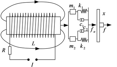
The MA structure and schematic diagram are indicated by Fig. 1 and Fig. 2. It is mainly made of the push rod, the preload mechanism, the magnetostrictive rod, the driving and bias coil, where the preload mechanism is comprised of preload spring, push rod and preload screw. The polarization magnetic field of the bias coil can not only make magnetostrictive rod deform in a linear region but also prevent the multiplier phenomenon affecting control precision. Then, when an alternating current is passed through the driving coil, the magnetostrictive rod can generate an alternating magnetic field as well, which causes a dynamic redistribution of magnetic field domains in the magnetostrictive rod. Furthermore, the telescopic length can be obtained microscopically to promote a displacement, which can thrust the output push rod. Thus, electromagnetic energy can be converted into mechanical energy.
In Fig. 1 – (1) the top cover screw, (2) the output push rod, (3) the top cover, (4) the preload spring, (5) the jacket, (6) the driving coil, (7) the bias coil, (8) the magnetostrictive rod, (9) the preload screw, (10) the bottom cover screw, (11) the bottom cover.
Fig. 1Structure diagram of the magnetostrictive actuator
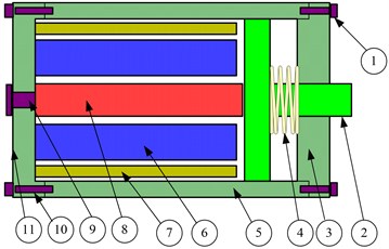
Fig. 2Schematic diagram of the magnetostrictive actuator
Based on the Jiles-Atherton theory, which reflects nonlinear hysteresis characteristics of the magnetostrictive actuator, it can accurately match the theoretical simulation and experiment by the structure optimization and parameter identification. Then, the partial differential equations of the magnetization process are established by magnetic domain and piezomagnetic theory [19, 20]. Moreover, its dynamics equations are also set up with the consideration of the mass and damping effect of magnetostrictive rod. The specific equations are as given below:
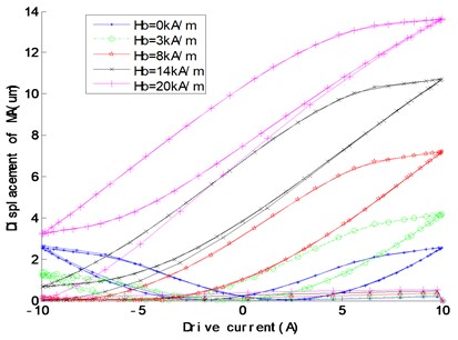
where is the effective magnetic field strength, is the external driving magnetic field strength. it’s value is the sum of the driving magnetic field ( is the number of turns in per unit coil length, is a driving current) and bias magnetic field , is the molecular field parameter of interacting magnetic torque, is the saturation magnetostrictive coefficient, is the constant preload stress, is the vacuum permeability, is the saturation magnetization, is the axial magnetostriction strain, is the shape factor of non-hysteresis magnetization, is the irreversible loss coefficient, is the integrated magnetic domain coefficient, is the reversible coefficient, the sign parameter +1 when 0 and –1 when 0, is the non-hysteresis magnetization, is the irreversible magnetization, is the reversible magnetization, is the total magnetization., , , , are respectively the damping, density, length, cross-sectional area and axial compliance coefficient of the magnetostrictive rod, , , are respectively the equivalent mass, damping and stiffness coefficient of the magnetostrictive rod. ,, are respectively the equivalent mass, damping and stiffness coefficient of the end load. Based on Eqs. (1-8) and experiments, the displacement responses to the preload and the bias magnetic field are shown in Fig. 3 and Fig. 4, then we can optimize and choose proper parameters of the preload and the bias magnetic field, which can make the actuator work perfectly within an approximately linear range and a larger displacement.
Fig. 3Displacement changes with the preload
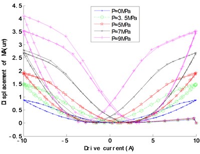
Fig. 4Displacement changes with the bias magnetic field
3. The active control system model
In the present paper, the active vibration isolation system model is shown in Fig. 5, , , are respectively the mass, damp and stiffness of the upper isolated device.
Fig. 5The active vibration isolation system model based on the magnetostrictive actuator
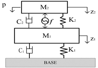
Here, all of them are respectively equal to , and in Eq. (7) or Eq. (8) as well. , and are the mass, damp and stiffness of the middle isolation platform. is the output force of the magnetostrictive actuator, , , , , and are respectively the displacement, velocity and acceleration of the upper isolated device () and the middle platform (). Consequently, the isolation system dynamics equations can be obtained as Eq. (9):
Take as the state variable, and the force transmitted to the foundation as the state space output . Then, the state equation of Eq. (9) can be written as:
where:
By Eq. (10), we can get that the system is completely passive vibration isolation if 0.
4. Design and analysis of the controller
4.1. System descriptions
Let the system state equation as Eq. (11):
where is the state variable, and is the control input, when the system reaches the ideal sliding mode 0, which can be described as Eq. (12):
The solution of Eq. (12) is known as an equivalent control in the sliding mode region, the equivalent control is designed for the absence of external perturbations in certainty system. Its robustness will be significantly affected by disturbances. Therefore, it is important to study on the controller design with disturbances. Then, the system state space is expressed as follows:
where , are the state variable and the control input, is the external disturbances. So, the active vibration isolation system is combined specifically with Eq. (10):
where:
4.2. The design of sliding mode controller using neural network
The sliding mode control is an effective control way, its advantages are that the system is totally unrelated with external disturbance and parameter perturbations in sliding mode [21, 22]. Based on the state space Eq. (14), the switching function can be designed as Eq. (15):
where is the switching surface, is the state variable, is the switching matrix. In this paper, the approaching exponential law of the saturated function is adopted as a control method:
where is the speed of the moving point approaching the switching surface, is the saturation function, is the approaching exponential coefficient. As a switch control, there is chattering phenomenon in traditional sliding mode. Therefore, the control parameter and should be modified to improve the controller stability. Here, a linear function is established between and as Eq. (17), which can meet the adaptive requirements for the sliding mode controller:
where is the modification coefficient, also has a significant influence on system chattering. Therefore, a hybrid algorithm, the RBF neural network sliding mode controller is designed to eliminate chattering phenomenon, the RBF neural network is a kind of three-layer feedforward neural network and its training speed is 103-104 times as fast as traditional BP neural network [23,24]. With a good generalized ability, it can approximate any continuous function with a higher accuracy. In this paper, it is used to improve the sliding mode controller. Take the as the network input, and the exponential approaching coefficient as the network output. The details are as followings:
where is the weight of RBF neural network, and is the Gaussian function:
where is the network center vector, is the neurons width. Take the displacement of the middle platform as the adjustment indicator:
Then the adjustment algorithm of network weights can be expressed as:
where depends on the sign, its value can be compensated by the weight values. is proportional with in active control, so it can be written as 1, , and then the weight adjustment algorithm can be modified as:
Moreover, the learning algorithm of network weights is expressed as:
where is the neural networks learning rate, , is inertial coefficient, . Substituting Eq. (14) and Eqs. (16-18) into Eq. (15), we get the RBF neural network sliding mode control law as Eq. (24):
4.3. Controller stability analysis
In this paper, the Lyapunov theory is used to prove the stability of the RBF neural network sliding mode controller [25], take the Lyapunov function as Eq. (25):
In continuous conditions, the first derivative of the Lyapunov function can be written as:
By substituting Eqs. (15-17) and Eq. (18) into Eq. (26), we can get:
where 0 is the only equilibrium point when 0, so the RBF neural network sliding mode controller can satisfy the conditions of Lyapunov asymptotic and overall stability, which shows the controller designed above is stable.
5. Co-simulation
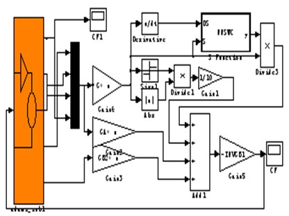
First of all, we need to build a virtual prototype model of the active vibration isolation system in Adams Software (the parameters will be shown in numerical simulation). And the active control force of the magnetostrictive actuator will be simplified to an interaction force between the upper isolated device and the middle platform, external excitation and system output are defined as well. In addition, the RBF neural network sliding mode control algorithm will be compiled in MATLAB/Simulink environment. It can connect input and output interfaces defined by Adams and MATLAB/Simulink. Thus, the closed-loop co-simulation model can be acquired. The Adams virtual prototype model, a double-layer vibration isolation platform consisting of a water pump, is illustrated in Fig. 6, and Adams and MATLAB/Simulink co-simulation model is shown in Fig. 7.
Fig. 6The Adams virtual prototype model of the vibration isolation system
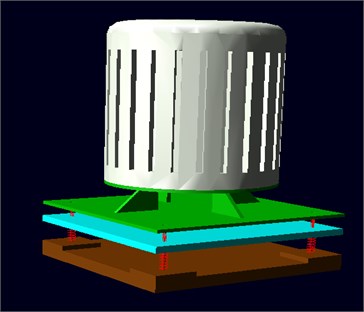
Fig. 7The co-simulation model of Adams and MATLAB/Simulink
6. Numerical simulations
The system modal frequency is 3.2 Hz, 16.7 Hz by Adams analysis, in order to verify the model correctness and control reasonableness. and random excitation are applied to calculate the force transmitted to the foundation, which can obtain the isolation system effect, and some simulation parameters are: 1200, 20 kA/m, 7102 A/m, –0.001, 7.65×10⁵ A/m, 1.005×10⁻⁶, 3283 A/m, 0.18, 1.3×10⁻¹¹, 1.0×10⁻⁸ m2/N, 3000 kNs/m2, 9250 kg/m3, 8.6×10⁻⁴m, 78.5×10⁻⁶ m2, 22.5 kg, 290.544 Ns/m, 190000 N/m, 105.42 kg, 302.7 Ns/m, 57016.2 N/m, the specific simulation results are shown as Figs. 8-12.
The control-off and control-on respectively denote the passive vibration isolation and the active vibration isolation. Fig. 8-11 and Table 1 show that, compared with the passive vibration isolation under single-frequency, multi-frequency and random signal excitation, the RMS values of the force transmitted to the base are greatly reduced by active control, and the external excitation is also effectively attenuated. While the former is respectively 51.3769 %, 4.7628 %, 93.0617 % and 32.9105 % in passive vibration isolation, and 4.3784 %, 0.5231 %, 2.0644 % and 7.6101 % in active vibration isolation. Therefore, the active vibration isolation system, based on the neural network sliding mode control, has an obvious control effect.
Fig. 8The force transmitted to the foundation with p1=sin(2π*4*t) excitation
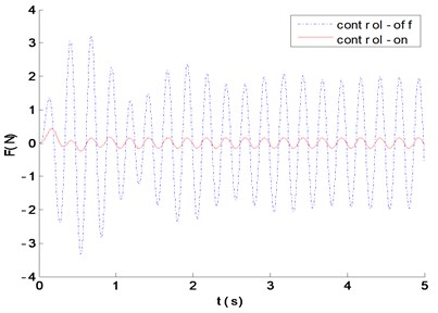
Fig. 9The force transmitted to the foundation with p2=sin(2π*30*t) excitation
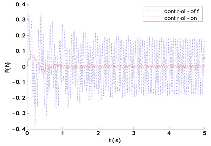
Fig. 10The force transmitted to the foundation with p3=sin(2π*5*t)+0.2sin(2π*30*t)+0.1sin(2π*60*t) excitation
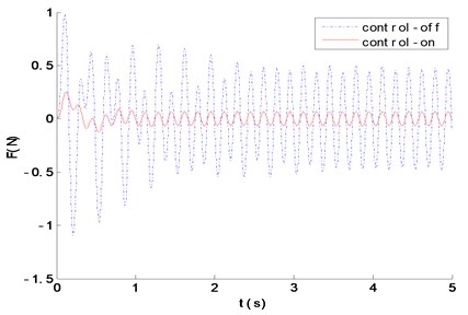
Fig. 11The force transmitted to the foundation with white noise excitation
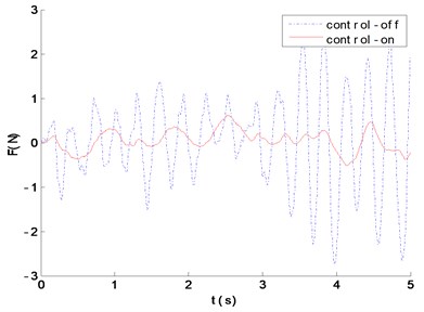
Table 1Vibration isolation performance comparison
4 Hz | 15 Hz | 5 + 30 + 60 Hz | Random excitation | |
RMS of excitation | 2.8869 | 2.8869 | 2.8869 | 3.1537 |
RMS of passive isolation (control-off) | 1.4832 | 0.1375 | 2.6866 | 1.0379 |
RMS of active isolation (control-on) | 0.1264 | 0.0151 | 0.0596 | 0.2407 |
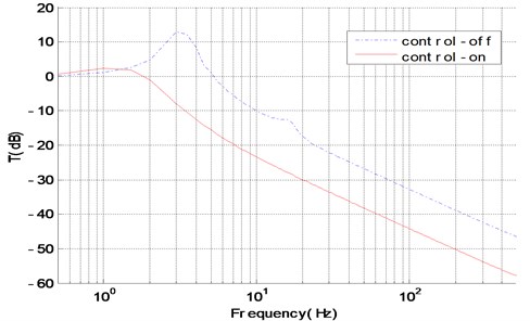
The force transmissibility curve is shown in Fig. 12, which demonstrates the natural frequencies corresponding to the two peaks of the passive isolation system, are perfectly matched with theoretical calculation, and the active isolation in first and second-order modal obtain a perfect isolation effect with 20 dB and 15 dB. The cross point frequency is 1.23 Hz, and there is a poor effect on the active vibration isolation when the excitation frequency is lower than the cross point, but the active vibration isolation has a better isolation effect when the excitation frequency is higher than the one, which will not only make up for the lack of passive vibration isolation in low-frequency, but also effectively broaden the system isolation frequency bandwidth.
Fig. 12The force transmission with control-on and control-off
7. Conclusions
Based on Jiles-Atherton theory and experiments, a nonlinear model of the magnetostrictive actuator is used for the active vibration isolation in a wide frequency range. And the sliding mode controller is modified by neural network to eliminate chattering problems, its stability is analyzed by Lyapunov theory as well. At last, the Adams dynamics model of the active vibration isolation is also established to carry out the co-simulation using Adams and MATLAB/Simulink. The results exhibit that, compared with the traditional passive vibration isolation, the active control with RBF neural network sliding mode control is more effective under the conditions of single-frequency, multi-frequency and random excitation. And the neural network sliding mode controller has a good control performance, widening the isolation band, improving system response speed, effectively reducing the force transmitted to the foundation and eliminating the first and second-order system resonance peak, all of which can improve the isolation performance. Moreover, the algorithm proposed in this paper has some practical meaning for the design and engineering applications on the isolation system, and the co-simulation modelling method also provides a new research method for the isolation system.
References
-
Zuo L., Jacques J., Slotine E. Robust vibration isolation via frequency-shaped sliding control and modal decomposition. Journal of Sound and Vibration, Vol. 285, Issue 2005, 112, p. 3-1149.
-
Hoque M. E., Mizuno T., Ishino Y., Takeshi M. A six-axis hybrid vibration isolation system using active zero-power control supported by the passive weight support mechanism. Journal of Sound and Vibration, Vol. 329, Issue 17, 2010, p. 3417-3430.
-
Kyihwan P., Sangyoo K., Dongyoub C. An active vibration isolation system using a loop shaping control technique. IEEE/ASME International Conference on Mechatronics and Embedded Systems and Applications, Beijing, China, 2008, p. 586-590.
-
Kim S. J., Dean R., Flowers G., Dean R. Active vibration control and isolation for micromachined devices. Journal of Mechanical Design, Vol. 131, Issue 9, 2009, p. 1-6.
-
Vimalajuliet Sathishkumar R. A., Prasath J. S. Terfenol-D: a high power giant magnetostrictive material for submarine mapping. International Journal of Engineering Science and Technology, Vol. 2, Issue 12, 2010, p. 7165-7170.
-
Sato E., Fujita T. Semi-active seismic isolation system with controllable friction dampers using hydraulic system driven by giant magnetostrictive actuators. Transactions of the Japan Society of Mechanical Engineers, Part C, Vol. 73, Issue 6, 2007, p. 1723-1730.
-
Hu S. F., Zhu S. J., Lou J. J. High-precision control of giant magnetostrictive actuator based on cmac neural network. Journal of Vibration and Shock, Vol. 28, Issue 3, 2009, p. 68-72.
-
Lau H. Y., Liu K. P. Feasibility of using GMM based actuators in active control of journal bearing system. Proceedings of the World Congress on Engineering, London, U.K, 2009, p. 1493-1498.
-
Braghin F., Cinquemani S., Resta F. A model of magnetostrictive actuators for active vibration control. Sensors and Actuators A: Physical, Vol. 165, Issue 2, 2011, p. 342-350.
-
Zhang X. H., Liu Y. G., Fu Y. L. Novel model of active vibration isolation based on giant magnetostrictive actuator. Journal of Beijing University of Aeronautics and Astronautics, Vol. 33, Issue 11, 2007, p. 1317-1320.
-
Li Y. L., Xu D. L. Dynamic effects of delayed feedback control on nonlinear vibration isolation floating raft systems. Journal of Sound and Vibration, Vol. 333, Issue 13, 2014, p. 2665-2676.
-
Chang C. M., Wang Z., Spencer B. F. Application of active base isolation control. Sensors and Smart Structures Technologies for Civil, Mechanical, and Aerospace Systems, Vol. 7292, Issue 39, 2009, p. 1-12.
-
Wang Y., Dyke S. Modal based LQG for smart base isolation system design in seismic response control. Structural Control and Health Monitoring, Vol. 20, Issue 5, 2013, p. 753-768.
-
Karthikeyan C., Prakash S. FxLMS algorithm with feedback neutralization for active vibration control. Institute of Smart Structures and Systems, Vol. 1, Issue 1, 2012, p. 23-33.
-
Lee T. Y., Chen P. C. Sliding mode control for nonlinear isolated bridges. Journal of Earthquake Engineering, Vol. 15, Issue 1, 2011, p. 582-600.
-
Yan X. G., Spurgeon S. K., Edwards C. Robust sliding mode observer with parameters estimation for a class of nonlinear time-delay systems. Proceedings of the 44th IEEE Conference on Decision and Control, and the European Control Conference, Atlanta, Georgia, USA, 2005, p. 987-992.
-
Zhu D. L., Qin J. Y., Zhang Y. Research on co-simulation using ADAMS and MATLAB for active vibration isolation system. International Conference on Intelligent Computation Technology and Automation, Changsha, China, Vol. 2, 2010, p. 1126-1129.
-
Zhou J. P., Zhang Z. Y., Feng G. P., Hua H. X. Modeling and simulation of active-passive vibration isolation of machinery with flexible base. Journal of Vibration and Shock, Vol. 27, Issue 11, 2008, p. 97-100.
-
Pop N. C., Caltun O. F. Jiles-atherton magnetic hysteresis parameters identification. Acta Physica Polonica A, Vol. 120, Issue 3, 2011, p. 491-496.
-
Knypiński Ł., Nowak L., Sujka P., Radziuk K. Application of a PSO algorithm for identification of the parameters of Jiles-Atherton hysteresis model. Archives of Electrical Engineering, Vol. 61, Issue 2, 2012, p. 139-148.
-
Liu J. K. MATLAB Simulation for Sliding Mode Variable Structure Control. Tsinghua University Press, Beijing, 2005.
-
David Y. K., Vadim I. U. A control engineer’s guide to sliding mode control. IEEE Transactions on Control System Technology, Vol. 3, 2004, p. 156-164.
-
Yu S., Alici G., Shirinzadeh B., Smith, J. Sliding mode control of a piezoelectric actuator with neural network compensating rate-dependent hysteresis. Proceedings of the 2005 IEEE International Conference on Robotics and Automation Barcelona, Spain, 2004, p. 3641-3645.
-
Ameziane M., Sefriti B., Boumhidi J., Slaoui K. Neural network sliding mode control for a photovoltaic pumping system. Journal of Electrical Systems, Vol. 9, Issue 3, 2013, p. 380-391.
-
Oliveira R. C., de Oliveira M. C., Peres P. L. Convergent LMI relaxations for robust analysis of uncertain linear systems using lifted polynomial parameter-dependent Lyapunov functions. Systems Control Letters, Vol. 57, Issue 8, 2008, p. 680-689.
Cited by
About this article

This work was supported by the National Natural Science Funds of China (51579242, 51509253) and the Key Scientific Research Foundation Project of Naval Submarine Academy (42551B1408). And the authors also wish to thank the anonymous reviewers for their valuable comments and suggestions.
