Abstract
The paper investigates the application of the Artificial Neural Network (ANN) in modeling of double-link flexible robotic manipulator (DLFRM). The system was categorized under multi-input multi-output. In this research, the dynamic models of DLFRM were separated into single-input single-output in the modeling stage. Thus, the characteristics of DLFRM were defined separately in each model and the coupling effect was assumed to be minimized. There are four discrete SISO model of double link flexible manipulator were developed from torque input to the hub angle and from torque input to the end point accelerations of each link. An experimental work was established to collect the input-output data pairs and used in developing the system model. Since the system is highly nonlinear, NARX model was chosen as the model structure because of its simplicity. The nonlinear characteristic of the system was estimated using the ANN whereby multi-layer perceptron (MLP) and ELMAN neural network (ENN) structure were utilized. The implementation of the ANN and its’ effectiveness in developing the model of DLFRM was emphasized. The performance of the MLP was compared to ENN based on the validation of the mean-squared error (MSE) and correlation tests of the developed models. The results indicated that the identification of the DLFRM system using the MLP outperformed the ENN with lower mean squared prediction error and unbiased results for all the models. Thus, the MLP provides a good approximation of the DLFRM dynamic model compared to the ENN.
1. Introduction
Robotic manipulators are extensively used in a wide range of industries that ranged from simple pick and place task to more complex operations such as those in the field of space exploration, automotive industry, electronic based industry, oil and gas industry and the medical field. They are cost effective and were proven to be more reliable than humans. Previously, robotic manipulator structures were generally large and heavy that resulted in rigid arm and stiff joint designs. Thus, their usage is limited to light loads and their movement is slow. Hence, the conventional design is not favorable in current industries as it is not efficient in term of speed, productivity and power consumption. Moreover, it has become a requirement for any engineering systems to have a lighter structure.
Hitherto, there are several well-established dynamic models of the system ranging from simple model such as the lumped parameters to complex models such as the assumed mode method (AMM) and the finite element method (FEM). Many papers have reported the implementation of AMM and the finite FEM toward designing an efficient controller for flexible manipulator system. They offer better accuracy as compared to lump parameters model. In [1] mentioned that studies on the dynamics modeling of flexible manipulator has been well documented in text books. Recent studies by [2, 3] utilized the Finite Element Method (FEM) when developing the model of two link flexible manipulator. The first model considered the concurrent large deflection in a system and the second model included the significant dynamics associated with the system. Apart from that, Assume Mode Method is used in [4] whereby the modeling was confirmed with the frequency domain obtained from experiments. Paper [5] exploited Assume Mode Method by incorporating sensor and payload. The drawbacks of applying these dynamic modeling is that there are assumptions that need to be taken care of to reduce the complexity of the system. In some works, linearized models were used. However, these linear models did not capture the non-linear dynamics of the flexible robot.
System identification has been used over the last two decades and had recently received a lot of attention for its ability to find an accurate model of dynamics systems. It was used extensively in many flexible structures applications such as the flexible beam modeling [6, 7], flexible plate modeling, [8, 9], single-flexible manipulator modeling [10], double link flexible manipulator [4, 11], flexible mounted pipe applications modeling [12] and many more. Therefore, there was a high motivation to use the system identification technique to develop a dynamic model that characterised the DLFRM based on the collected data from a real plant. The utilization of these methods enabled the developed models to represent the dynamic characteristic of the system and avoided the complexities associated with mathematical and physical model development. Several estimations using parametric approaches have been utilized for modeling the flexible manipulators such as the conventional RL [13], RELS [14] and RLS and least mean square (LMS) [15]. Apart from that, parametric approaches using intelligent methods have attracted many researchers to model the system such as, Genetic Algorithm [16] particle swarm optimization (PSO) [17], Bacteria Foraging Algorithm [18], Differential evolutionary (DE) algorithm [19] and Cuckoo Search Algorithm [20]. A number of research works considered parametric model structure because of its simplicity. Most of the works used simulated data which are less precise than utilizing real time data.
In this study, non-parametric approaches were utilized to characterize the dynamics of the DLFRM using the experimental data. The non-linear system is preferable because it captures the real non-linear dynamics of the flexible robot and provides a good platform of control application. It is reported that ANN identification technique has been increasingly applied into many nonlinear systems since its inception. Among all the regressors, NARX has an algebraic relationship between prediction and past data only and thus, it has a predictor without feedback which makes the model less complicated. Until now, there are very limited research work on developing nonlinear modeling for the system. The attempt on using non-parametric NARMAX model in [21] showed that the work was inclined to adaptive control. Though NARMAX model structure showed good approximation, it could give over fitting estimation as the model has predictor with feedback.
There are various examples of NARX model based system identification that have successfully accomplished very complex nonlinear system, for example, the modeling of Humanoid Robot 3-DOF [22], robot catheter manipulating system [23], electromechanical manipulator [24] and steel surface roughness for the milling machine [25]. Apart from that, ANN is used for representing flood level water modeling [26], solar radiation model [27], Industrial power plat gas turbine [28], magnetic levitation system [29] and meteorological wireless sensor network [30]. Therefore, the present study will carry out the system identification of DLFRM using Neural Network Auto Regressive model with eXogenous inputs (NNARX).
The paper presents the intelligent modeling of DLFRM using non-parametric approaches utilizing data from the experimental rig which none of previous research have carried out in the modelling of DLFRM. Since the system was categorized under MIMO system, the interaction of matrices in the model is a major challenge. The matrices must be decoupled before it can be used in control strategies. In this proposed method, the model of DLFRM were decentralized in the modeling stage. The dynamic models of DLFRM were separated into single-input single-output system. Thus, the characteristics of DLFRM were defined in each model using the collected data and the coupling effect was assumed to be minimized. The collected data was then estimated using ANN by using NARX model structure.
2. Design and development of DLFRM
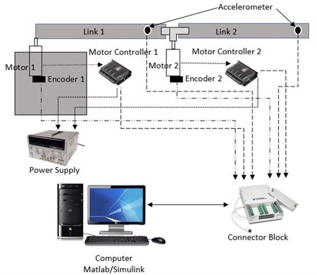
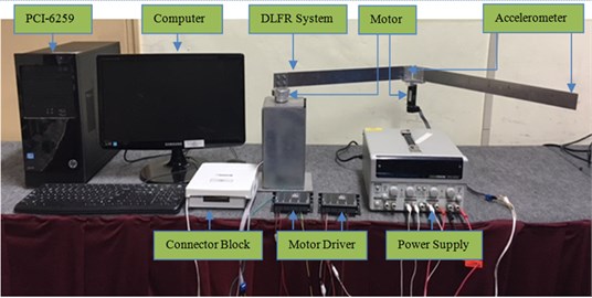
The schematic diagram in Fig. 1(a) shows a planar double link flexible manipulator (DLFRM). A rectangular steel base was constructed to hold the overall system. The connector shaft coupling was fabricated using the aluminium block to attach the second motor with link 1 and link 2. It was designed in such a way that allowed movement of second link at ±90°. The first link (thickness: 2 mm) held the 30 mm Maxon DC motor and the second link. Meanwhile the second link (thickness: 1 mm) moved freely. A 40 mm Maxon DC motor was attached at the hub of link 1. The ESCON 50/5 servo controller was used as a motor driver for both motors. An encoder of model HEDL-5540 was utilized to measure the angular position of each of the motor. The miniature and lightweight single axis accelerometers, type 8640A50 were positioned at the end of each link. The accelerometers converted the mechanical signals produced by manipulators to electrical signal. National Instruments (NI) data acquisition card model PCI-6259 and its input output connector block SCC-68 were employed as the interface unit in this study. A personal computer (PC) with Intel core I5, 2.93 GHz was operated as a processer of the system. Meanwhile, MATLAB/Simulink was implemented as the environment for the development of the controller. The main toolbox of the Real Time Window Target was executed to interface the system. The actual view of DLFRM is shown in Fig. 1(b).
Fig. 1a) Schematic diagram of DLFRM, b) double link flexible robotic manipulator rig
a)
b)
3. System identification
In general, there are several steps involved in system identification (SI). They are data acquisition, model structure selection, model estimation and model validation. In modeling the dynamic system, data acquisition provides an important role whereby numerous set of data are collected. After the model structure is determined, the main task of identification is to estimate the model parameters. The estimated model must have similar properties to that of the true one and predict future values of the output. Once a model of the system is obtained, it is required to verify the model. Model validity tests are procedures to detect the adequacy of a fitted model. This is very important to ensure the model developed is sufficient in representing the system.
4. Experimentation set up and data acquisition
The experimental set up must be verified before the data can be used for further analysis of SI. Two tests were carried out that is experimental test and impact test. From the tests, the results showed that the data collected from experimental set up was suitable for SI. The details of those tests can be found in [31].
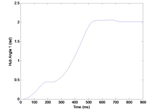
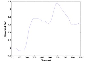
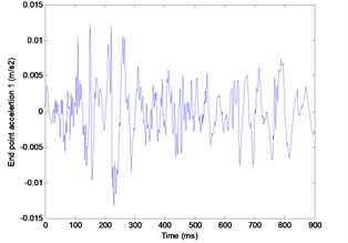
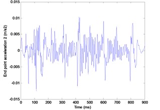
In data acquisition, the input-output data required for the modeling process were collected experimentally using the DLFRM test rig described in Section 2. Simulink program was developed as the tool for collecting the data. A different bang-bang signal with ±0.7 V amplitude and ±0.5 V amplitude were used to provide the required torque to excite the double-link simultaneously. Four outputs were collected from two encoders and two accelerometers which represent the hub angles and end point accelerations of each link respectively. The experiment was carried out for the duration of 9 s with sampling time of 0.01 s. The experimental hub-angle 1, hub-angle 2, end point acceleration 1 and end point acceleration 2 responses were captured and recorded as in Fig. 2(a)-(d).
Fig. 2a) Experimental hub-angle 1 response, b) experimental hub-angle 2 response, c) experimental end point acceleration 1 response, d) experimental end point acceleration 2 response
a)
b)
c)
d)
5. Model estimation by using neural network
In this work, Neural network was used to predict the non-parametric model (model estimation). Neural networks architectures mimic biological neural networks. The networks are made up of a great number of highly interconnected identical or similar simple processing units. The important networks feature is its adaptive nature. The networks can learn the knowledge it acquired from the environment. The neural networks used for system modelling usually apply two basic processing elements that is perceptron and the basis function neuron. The perceptron is a nonlinear model of a neuron. This simple neural model consists of two basic parts: a linear combiner and a nonlinear activation function. A linear combiner computes the product of input vector, of the neuron and the parameter vector, . And a nonlinear activation function applied to the output of the linear combiner. The purpose of system identification is to identify the dynamic systems. Thus, the neural architectures are emphasised on dynamic neural networks.
5.1. Multi-layer perceptron
The research utilized back propagation for multi-layer perceptron (MLP) neural network for modeling four sets of a Single Input Single Output (SISO) DLFRM system. The MLP is the most popular of the neural network family because of its ability to provide simple model and estimate a highly complicated formula association.
The MLP consist of one layer of nodes that forms the input layer whilst a second layer forms the output of NN, with a number of intermediate or hidden layers existing between them. The layer of network forms the input layer, , the output, , with a number of neuron, , a hidden layer that has different weight of strength, . The function can be linear, threshold, sigmoid, hyperbolic tangent and radial basis. The mapping allows the network to predict the output, as close to the true output. The MLP output is presented in Eq. (1):
Levenberg-Marquardt (LM) is chosen for network training due to short convergence time although it takes substantial amount of memory than another algorithm. The LM optimizes the error by minimizing the residual, based on the criterion in Eq. (2):
where is the training data set.
5.2. ELMAN neural network
Another class of Neural Networks that is Elman neural networks (ENN). ENN is two-layer back propagation networks, with the addition of a feedback connection from the output of the hidden layer to its input. This feedback path allows Elman networks to learn, recognize, and generate temporal patterns, as well as spatial patterns. Gradient descent with momentum and adaptive learning rate back propagation is chosen for the network training function. It updates weight and bias values according to gradient descent momentum and an adaptive learning rate. Back propagation is used to calculate derivatives of performance with respect to the weight and bias variables . Each variable is adjusted according to gradient descent with momentum as presented in Eq. (3):
where is the former adjustment to the weight or bias.
5.3. NARX model structure
NARX model is the nonlinear generalization of the well-known ARX model, which constitute a standard tool in the linear black-box identification. For estimating the nonlinear part of the ARX structure, the neural network is utilized. The general NNARX model structure is shown in Fig. 5. The NNARX model structure regression vector is given by Eq. (4):
The regression vector is formed of past values of the input and output of the system. The OSA prediction of the NNARX model is given by Eq. (5):
where is the function realized by the neural network method.
5.4. Model validation
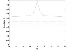
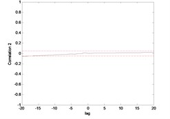
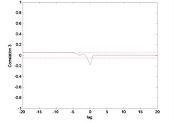
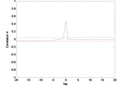
The validation phase is a must to ensure that the model being developed is adequate. The model validation is carried out by using three methods that is One Step Ahead (OSA) prediction, Mean Squared Error (MSE) and Correlation Test. The correlation functions are five as following:
where indicates the cross correlation function between and , is an impulse function. The model is developed using NARX structure that is a nonlinear system, thus all the five conditions must be fulfilled. The research used a range of 20 data to be used in the test. The 95 % confidence bands are implied which are approximately , ( data) and any significant correlation will be indicated by one or more points of the function lying outside the bands. Therefore, if the correlation functions are within the confidence intervals, the model is regarded as adequate [32].
6. Results and discussion
Several MATLAB programs have been created based on MLP and ELMAN NN for modeling the hub angle and end point acceleration from the voltage input to the hub-angle output utilizing the data obtained from the DLFRM test rig as described in section 2 of this study. The data set, consist of 900 data points, was split into two sets of 675 and 225 data points respectively. The first set (estimation set) was utilized for modeling phase whilst the second set (test set) was utilized for validation phase.
A heuristic method has been performed for the structure realization since there was no prior information about the appropriate delay numbers and the model structure. The input-output data were regulated during the exercise for the range of –1 and 1. There were three main factors that needed to be considered during the process and there were the number of delay signals, the size of NN structure or the number of neuron and the error. The last factor was assessed along the process of getting the best number of delay signals and the structure for each model. This was due to the stochastic behavioral of the procedure on getting the optimal model. It is worth noting that the criterion was used to select the best model based on validation MSE, modeling MSE and correlation tests.
In the earlier stage of investigation, the model was estimated by using NN with one hidden layer. However, the model estimation results were very poor. Then, additional hidden layer was added. As the layer increased to three, the estimation time became longer but there was no significant improvement as compared to the two layers. Thus, the model structure was fixed to two layers. In this research, the number of neurons start with 2 neurons in the first hidden layer, 2 neurons in the second hidden layer and one neuron in the output layer ([2 2 1] model structure). Delay number represent the input layer.
6.1. Modelling of hub angle
The modeling prediction result of hub angle 1 and 2 using MLP and ENN prediction structure were compared. Fig. 3 and 4 shows the MLP predictions of the joint angle. The validated data are indicated as a red vertical line located at point 675. It is observed from both graphs that the MLP could follow the actual data closely. The error between actual and predicted MLP output almost negligible or close to zero.
Fig. 3Output and estimated outputs of Hub angle 1 (MLP)
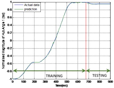
Fig. 4Output and estimated outputs of Hub angle 2 (MLP)
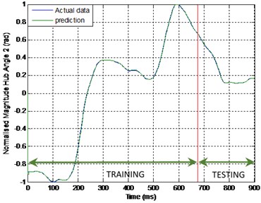
Fig. 5Output and estimated outputs of Hub angle 1 (ENN)
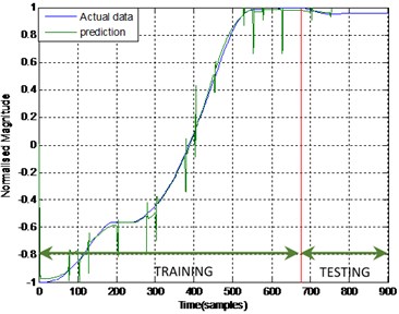
Fig. 6Output and estimated outputs of Hub angle 2 (ENN)
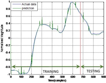
Meanwhile, Fig. 5 and 6 shows the ENN prediction of joint angle 1 and joint angle 2 for the same data. From the graphs, it was noticed that ENN can trace the actual data but there was a significant discrepancy between the actual data and predicted data. The deviation was even more noticeable on the validated data section. The error was substantial and cannot be disregarded.
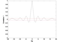
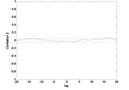
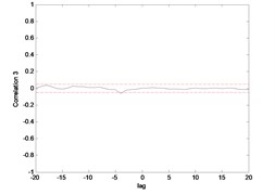
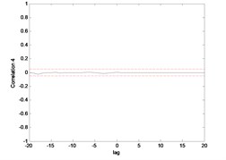
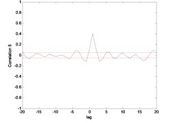
The correlation test for each link as depicted in Fig. 7 till Fig. 10. For the MLP, the results fall within 95 % confidence level thus confirmed the accuracy of the model. However, the correlations of the error for both models using ENN are obviously fall far-off 95 % confidence level.
Fig. 7Correlation test for hub angle 1 using MLP
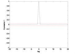
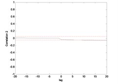
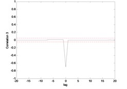
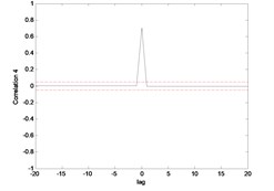
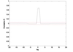
Fig. 8Correlation test for hub angle 2 using MLP
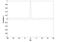
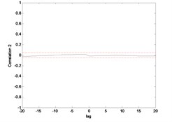
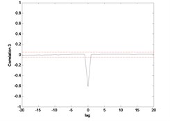
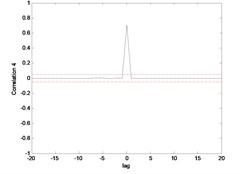
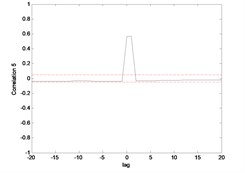
Fig. 9Correlation test for hub angle 1 using ENN
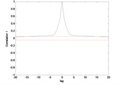
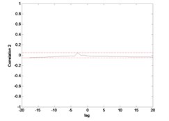
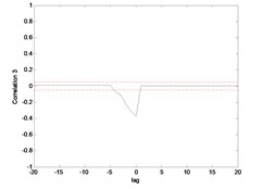
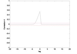

Fig. 10Correlation test for hub angle 2 using ENN
6.2. Modelling of end point acceleration
The same pattern was found in the model of the end point acceleration for both link 1 and 2 using MLP and ENN. The MLP was superior in predicting the model compared to ENN. The error between the actual and predicted MLP output was almost negligible or close to zero where there was no significant blue line observed in the Fig. 11 and 12. But, not in the case of ENN as the blue line can be observed clearly in Fig. 13 and 14 which indirectly portrayed the error in the prediction process.
Fig. 11Output and estimated outputs of E.P. acc.1 (MLP)
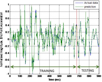
Fig. 12Output and estimated outputs of E.P. acc.2 (MLP)
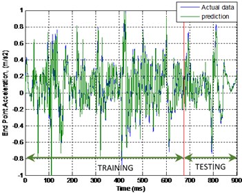
Fig. 13Output and estimated outputs of E.P. acc.1 (ENN)
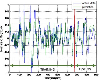
Fig. 14Output and estimated outputs of E.P. acc.2 (ENN)
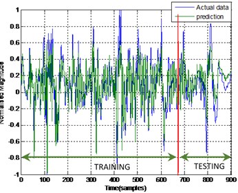
Fig. 15Correlation test for end point acc. 1 (MLP)
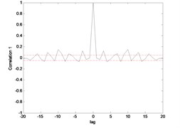
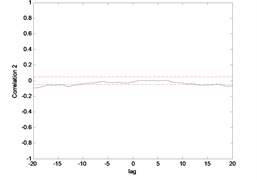
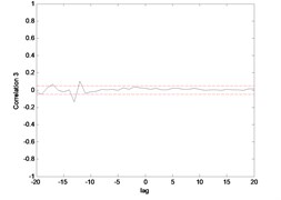
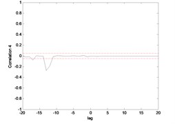
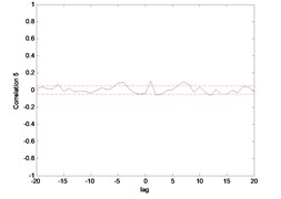
Fig. 16Correlation test for end point acc. 2 (MLP)
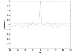
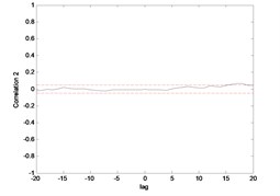
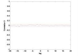

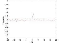
Fig. 17Correlation test for end point acc. 1 (ENN)
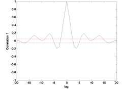
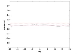
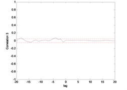
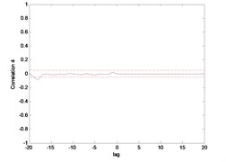

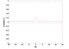
Fig. 15 till Fig. 18 show the correlation test for the end point acceleration of both link 1 and 2. For the MLP, the results fall within 95 % confidence level thus confirmed the accuracy of the model. However, the correlations of the error for both models using ENN were obviously far-off the 95 % confidence level. Thus, it can be concluded that both models predicted by ENN were biased.
Fig. 18Correlation test for end point acc. 2 (ENN)
6.3. Overall comparative assessment and discussion
The MLP and ELMAN were two NN structures that were utilized to perform a non-parametric modelling of the DLFRM hub-angle. The heuristic method was used to find the optimized model. The model realization starts by fixing the model structure to [2 2 1]. The effect of the increasing delay number on to the MSE results of the MLP was observed. It was found that, the MSE reduced until the delay number of input-output is 8 for both hub angle 1 and 2.
Thereafter, the value of the MSE increased in trend. The time taken to converge also increases. At this point, the delay numbers are fixed to 8 while the model structure is changed. There is no significant improvement of the MSE as the model structure increased. The similar method was implemented for the model realization of the end point acceleration. The same trend was observed in the first part of the modeling. The MSE reduced until the delay number of input-output for both links is 6. However, the changed in model structure did significant improvement of MSE until it reached the model structure [8 8 1].
MLP was able to follow the actual output very well. Meanwhile, the model optimized by ENN was capable to track the actual output with the bigger error range. The summary of the best model and overall comparative performance for the hub angle and end point acceleration are tabulated in Table 1.
Table 1Summary of the best performance achieved in non-parametric modelling
Model | Model structure | (s) | MSE | Correlation test | |
MLP | Hub 1 | MS: [2 2 1], Delay: 8 | 3 | 0.0000685 | Unbiased |
Hub 2 | MS: [2 2 1], Delay: 8 | 3 | 0.000752 | Unbiased | |
End point acceleration 1 | MS: [8 8 1], Delay: 6 | 3 | 0.0025 | Unbiased | |
End point acceleration 2 | MS: [8 8 1], Delay: 6 | 3 | 0.0049 | Unbiased | |
ENN | Hub 1 | MS: [2 2 1], Delay: 5 | 2 | 0.0047 | Biased |
Hub 2 | MS: [ 2 2 1], Delay: 5 | 2 | 0.0023 | Biased | |
End point acceleration 1 | MS: [2 2 1], Delay: 8 | 3 | 0.018 | Biased | |
End point acceleration 2 | MS: [2 2 1], Delay: 8 | 3 | 0.015 | Biased |
7. Conclusions
In this work, NNARX model is developed for DLFRM. The links are maneuvered at various angles by giving bang-bang torque to the system. The movement of the motors are collected via the encoder. The vibration of the flexible arms was captured by using the accelerometer. The entire signal was transmitted to a data acquisition card for analog-to-digital conversion of the signal. In the second stage, the data was treated to acquire the system modeling. The modeling development is performed via simulation within MATLAB/Simulink environment. The structure of NARX model was used in consideration of the nonlinear system exhibits by DLFRM. The system was mapped out to construct four sets of separate models that represent the entire system of DLFRM. The performances of MLP and ENN models were assessed based on the validation mean-squared error, modeling mean-squared error and correlation tests. It was confirmed that the MLP attained superior mean-squared error value in all modeling and validation stages. It predicted well for the system response, and thus deliver superior model than ENN. The best model of the DLFRM which was obtained from MLP will be used in the subsequent development of control approaches for hub-angle and end-point acceleration of the DLFRM. The models produced through the proposed intelligent method was utilized for the controller parameters’ optimization. The models will be employed as preliminary test to explore and comprehend the control schemes reacting to the variation of control constraints or disturbances prior to the experimental study.
References
-
Chang T. K., Spowage A., Yoong C. K. Review of control and sensor system of flexible. Journal International Robot System, Vol. 77, Issue 1, 2015, p. 187-213.
-
Heidari H. R., Korayem M. H., Haghpanahi M., Feliu B. V. A new nonlinear finite element model for the dynamic modeling of flexible link manipulators undergoing large deflections. International Conference on Mechatronics, 2011.
-
Reddy M. P. P., Jacob J. Accurate modeling and nonlinear finite element analysis of a flexible-link manipulator. International Journal of Mechanical and Mechatronics Engineering, Vol. 8, Issue 1, 2014, p. 165-170.
-
Khairudin M., Mohamed Z., Husain A. R. System identification and LMI based robust PID control of a two-link flexible manipulator. Journal of Telecommunication, Computing, Electronics and Control, Vol. 12, Issue 4, 2014, p. 829-838.
-
Gripp J. A. D. B., Santos F. L., Bernardo C. R., Góes L. C. S. Modeling and identification of a two-link flexible manipulator. Symposium Series in Mechatronics, Section VII Robotics, Vol. 5, Issue 1, 2012, p. 1092-1101.
-
Jalil N. A., Mat Darus I. Z. System identification of flexible beam structure using artificial neural network. Proceedings of the 5th IEEE International Conference on Computational Intelligence, Modeling and Simulation, 2013.
-
Saad M. S. Evolutionary Optimization and Real-Time Self-Tuning Active Vibration Control of a Flexible Beam System. Ph.D. Thesis, Faculty of Mechanical Engineering, Malaysia University of Technology, 2014.
-
Mat Darus I. Z. M., Al Khafaji A.-A.-M. Nonparametric modeling of a rectangular flexible plate structure. International Journal of Engineering Application of Artificial Intelligence, Vol. 25, Issue 1, 2012, p. 94-106.
-
Tavakolpour A. R., Mat Darus I. Z., Tokhi O., Mailah M. Genetic algorithm-based identification of transfer function parameters for a rectangular flexible plate system. Engineering Applications of Artificial Intelligence, Vol. 23, Issue 8, 2010, p. 1388-1397.
-
Mohd Yatim H., Mat Darus I. Z. Intelligent parametric identification of flexible manipulator system. International Review of Mechanical Engineering, Vol. 8, Issue 1, 2014, p. 11-21.
-
Shawky A., Zydek D., Elhalwagy Y. Z., Ordys A. Modeling and nonlinear control of a flexible-link manipulator. Applied Mathematical Modelling, Vol. 37, Issue 23, 2013, p. 9591-9602.
-
Shaharuddin N. M. R., Mat Darus I. Z. System identification of flexibly mounted cylindrical pipe due to vortex induced vibration. Proceedings of the IEEE International Conference on Computer and Informatics, 2013, p. 30-34.
-
Mute D., Ghosh, Subudhi B. Iterative learning control of a single-link flexible manipulator based on an identified adaptive NARX model. Annual IEEE Indian Conference, 2013.
-
Pradhan S. K., Subudhi B. NARMAX modelling of a two-link flexible robot. Proceedings of Indian Conference, 2011, p. 1-5.
-
Shaheed M. H., Tokhi M. O. Dynamic modeling of a single-link flexible manipulator: parametric and non-parametric approaches. Robotica, Vol. 20, Issue 1, 2002, p. 93-109.
-
Md Zain B. A., Tokhi M. O., Md Salleh S. Dynamic modeling of a single link flexible manipulator using parametric techniques with genetic algorithms. Proceedings of 3rd UK Sim European Symposium on Computer Modeling and Simulation, 2009, p. 373-378.
-
Alam M. S., Tokhi M. O. Dynamic modeling of a single-link flexible manipulator system: a particle swarm optimization approach. Journal of Low Frequency Noise, Vibration and Active Control, Vol. 26, Issue 1, 2007, p. 57-72.
-
Supriyono H., Tokhi M. O. Parametric modelling approach using bacterial foraging algorithms for modelling of flexible manipulator systems. Engineering Applications of Artificial Intelligence, Vol. 25, Issue 5, 2012, p. 898-916.
-
Al Khafaji A.-A.-M., Shaharuddin N. M. R., Mat Darus I. Z. Evolutionary algorithm for identification of a flexible single-link manipulator system. World Scientific and Engineering Academy and Society Transactions on Systems and Control, Vol. 10, Issue 1, 2015, p. 58-75.
-
Al Khafaji A.-A.-M., Shaharuddin N. M. R., Mat Darus I. Z. Modeling of a flexible single-link manipulator using metaheuristic algorithms. International Review of Mechanical Engineering, Vol. 8, Issue 1, 2014, p. 1075-1092.
-
Pradhan S. K., Subudhi B. NARMAX modeling of a two-link flexible robot. Proceedings Annual IEEE India Conference: Engineering Sustainable Solutions, 2011.
-
Pham H., Anh H. Adaptive Trajectory modeling of humanoid robot 3-DOF arm using inverse neural MIMO NARX model. International Conference on Control, Automation and Information Sciences, 2012, p. 381-386.
-
Ma X., Guo S., Xiao N., Guo J., Yoshida S. NARX Model-based identification for the developed novel robotic catheter manipulating system. Proceedings of IEEE International Conference on Mechatronics and Automation, 2012, p. 2225-2229.
-
Meira A. S. Recursive nonlinear identification an electromechanical manipulator using the MIMO NARX model. International Journal of Innovative Research in Advanced Engineering, Vol. 2, Issue 1, 2015, p. 108-113.
-
Saric T., Simunovic G., Simunovic K. Use of neural networks in prediction and simulation surface roughness. International Journal of Simulation Modeling, Vol. 12, Issue 4, 2013, p. 225-236.
-
Ruslan F. A., Samad A. M., Zain Z., Adnan R. Flood water level modeling and prediction using NARX neural network: case study at Kelang river. 10th International Colloquium on Signal Processing and Its Applications, 2014, p. 7-9.
-
Mohammed L. B., Hamdan M. A., Abdelhafez E. A., Shaheen W. Hourly solar radiation prediction based on nonlinear autoregressive exogenous (Narx) neural network. Jordan Journal of Mechanical and Industrial Engineering, Vol. 7, Issue 1, 2013, p. 11-18.
-
Basso M., Giarre L., Groppi S., Zappa G. NARX models of an industrial power plant gas turbine. IEEE Transaction on Control Systems Technology, Vol. 13, Issue 4, 2005, p. 599-604.
-
Antić D., Milovanović M., Nikolić S., Milojković M., Perić S. Simulation model of magnetic levitation based on Narx neural networks. International Journal Intelligent System and Applications, Vol. 5, Issue 1, 2013, p. 25-32.
-
Baowei W., Xiaodu G., Li Ma, Shuang S. Y. Temperature error correction based on BP neural network in meteorological WSN. International Journal of Sensor Networks, Vol. 23, Issue 4, 2017, p. 265-278.
-
Annisa J. J., Mat Darus I. Z., Al Khafaji A.-A.-M., Tokhi M. O. Non-parametric modeling of double link flexible robot manipulator. Proceeding of the 19th International Conference on Climbing and Walking Robots and Support Technologies for Mobile Machines, 2016, p. 559-566.
-
Billings S. A., Zhu O. M. Non-linear model validation correlation tests. International Journal of Control, Vol. 60, Issue 6, 1994, p. 1107-1120.
Cited by
About this article

The authors would like to express their gratitude to Minister of Education Malaysia (MOE), University Technology Malaysia (UTM) and University Malaysia Sarawak (UNIMAS) for funding and providing facilities to conduct this research.
