Abstract
This paper describes the background of large multi-shaker test facility’s application. There are three major different methods to deal with the synchronous vibration control issues for these facilities. They are including using digital phase unit, analog phase unit and mimo-vibration controller. Finally, specific engineering application examples in the field of aerospace were given. The test results show that different methods have their own strength and weakness and choices have to be made to resolve the in-phase vibration control problems according to the multi-shaker test facilities’ configuration.
1. Introduction
Spacecraft dynamic testing in a laboratory environment has long been a successful method of experimentally determining the mechanical properties of a structure as well as a technique for providing a degree of confidence that the unit under test (UUT) can structurally and functionally withstand a special flight environment. The simplest and most common laboratory vibration test consists of a single shaker providing motion in a single mechanical degree-of-freedom. However, as the spacecraft’s size and weight grow, one single shaker is not capable of meeting the spacecraft mechanical test requirements, it is imperative to build large complicated multi-shaker system to address the issue of test requirements.
Most of the major space centers worldwide including ESTEC, NASA, etc. have constructed large vibration test facilities in recent years to meet the needs of large spacecraft’s environmental vibration test [1-2]. Currently, spacecraft’s vibration tests have been performed using sequencially-applied uniaxial loading. But for multi-shaker test facilities, how to ensure the multiple shakers moving in-phase remains a very difficult issue. In recent years, as the multi-shaker vibration test theory grow, there are a lot of engineering cases discussing how to use these new technologies [3-10]. This paper summarizes the major solutions around the world to ensure the multi-shaker in-phase movement, and then specific engineering cases in the field of aerospace industry were given. The test results show that different methods have their own advantages and disadvantages and one of them can be chosen to resolve the in-phase control problem of multi-shaker test facilities according to the configuration.
2. In-phase control method
Internationally, there are three major methods to ensure the multiple shakers moving synchronously. These are including using Digital PCU, Analog PCU, MIMO vibration controller. How to use these devices are introduced below in detail.
2.1. The 1st control method combined single-axis vibration controller and digital PCU
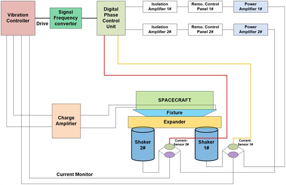
The first control method is to use vibration control system and phase control unit together in a dual-shaker sine vibration test facility. The vibration control system control the acceleration level of the specimen while the phase control unit control the phase of the two shakers. Fig. 1 shows the control principle of two separate control loops.
The external loop mainly controls the acceleration level of the two shakers. The multi-point average control method is employed during the test. The vibration controller updates the drive signal continuously based on the difference between the response level and the reference spectrum.
The internal loop mainly controls the moving phase of two shakers. In order to make the two shakers vibration in phase, the digital phase control unit updates the phase of the two drive signals based on the two voltage signals coming from the current sensors of the two shakers [11].
The digital PCU is capable of only resolving sine vibration test problem of multi-shaker facilities. This method requires that the loop control speed of PCU runs faster than that of vibration controller. Both of them should match well in operation.
Fig. 1Multi-shaker facility using digital PCU
2.2. The 2nd control method combined single-axis vibration controller and analog PCU
The principle of multi-shaker synchronous control using analog PCU is shown in Fig. 2. There is only one loop control during the test process.
The vibration controller only controls the test level of the shakers. Analog PCU only compensate the phase of the shakers during the test process rather than closed loop real-time control. The Analog PCU should be calibrated before the test according to the properties of the shakers and power amplifiers to obtain the gain and phase information. During the test process, the analog PCU corrects the drive signals and monitors the phase of the shakers using the feedback signals from the power amplifiers. It will shut down and decrease the drive signals quickly to zero if the phase difference among the shakers beyond the abort value to ensure the safety of the whole test system.
The analog PCU is not only capable of resolving sine vibration test problem, but random test problem as well. This method requires the PCU to calibrate periodically to ensure the right correction during the test process.
2.3. The 3rd control method only using MIMO controller without PCU
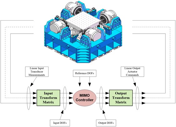
The principle of multi-shaker synchronous control using MIMO controller is can be seen in Fig. 3. For such type of multiple shaker tests, the question is emerging as how to configure the shakers for driving the table and how to configure the sensors for measuring the motion response. If more than linear measurements are required, then a matrix is used to transform the linear response into Degrees of Freedom. This matrix is what we called Coordinate Transformation Matrix determined by the geometry of sensors and shakers. There are two transformation matrices usually needed by the MIMO controller. One is located at the input to the MIMO control system and the other is located on the output from the MIMO control system. The MIMO controller renews the drive signals continuously according to the response of degree of freedom, reference spectrum and system frequency response function.
Fig. 2Multi-shaker facility using Analog PCU

For this type of multi-shaker test facility using the MIMO controllers, hydrostatic bearings are usually installed between the shakers and table. If only single axis motion is needed, the MIMO controller must cancel any cross axis or rotational vibration induced by load imbalance or structural resonance by setting the other unwanted reference spectrum at a very low level to produce pure translation or rotation [12].
Fig. 3Multi-shaker facility using MIMO controller
3. Specific cases in engineering application
3.1. Digital PCU in dual-shaker system
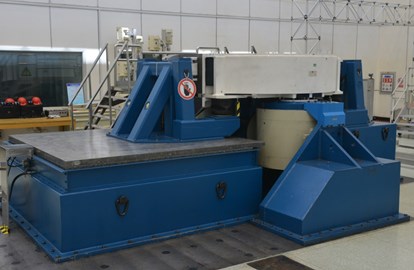
The large dual-shaker vibration test facility of BISEE in China consists of two 200 kN electrical shakers, horizontal pedestal, expander and slip table. Before the vertical vibration test, the expander with airbags and guide bearings is connected with the armatures of the two shakers. One end of the expander is fixed with the slip table while the other end is connected with the horizontal pedestal. While for the horizontal vibration test, the armatures of the two shakers are connected directly with the slip table through H-bars.
To ensure the two shakers moving synchronously, both of digital PCU and single-axis vibration controller are employed in this dual-shaker test facility which has completed major parts of China’s satellite vibration test. The phase correction accuracy can reach within ±10°.
Fig. 4The 400 kN dual-shaker vibration test facility of China
3.2. Analog PCU in Quadri-shaker system
The ESTEC’s quadri-shaker facility comprises a cluster of four 160 kN shakers topped with a 2500 kg magnesium table guided by sixteen hydrostatic bearings. The LMS SCADAS III controller and analog PCU are used in this facility to ensure the synchronization between the four shakers. As a matter of fact, the vibration control system, LMS SCADAS III running Test lab, sends one drive signal at the input of the amplifiers which is common to the four systems. Unbalances between amplifiers and shaker responses are dealt with by an analog phase control unit which is an off the shelf product of the shaker supplier.
The phase correction accuracy of this facility can reach within ±4°. It is able to test at the same time large heavy specimen against quasi-static load and very light specimen at very high acceleration level.
Fig. 5The 640 kN quadri-shaker system of ESTEC
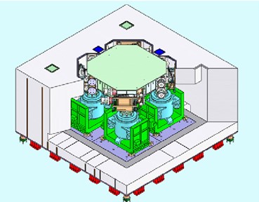
Another large multi-shaker test facility manufactured by BISEE in China consists of 1400 kN vertical vibration test system (VVS-1400) and 700 kN horizontal vibration test system (HVS-700). This large test system mainly includes vibration controller, PCU, shakers, power amplifiers, expander, slip table, external water cooling unit, etc. The vibration tests of large satellites and spacecrafts have been carried out by this test facility.
VVS-1400 consists of four shakers as the force source topped with a large head expander guided by 16 hydrostatic bearings while HVS-700 adopts a cluster of two shakers as the dynamic source moving a big slip table back and forth [13]. The big slip table is made of three small magnesium tables. The thrust force of each shaker is 350 kN.
To ensure the shakers moving synchronously, both of analog PCU and single-axis vibration controller are employed in this complicated test facility. It is able to test large heavy spacecrafts such as core capsules of space station. The phase correction accuracy of this facility can reach within ±5°.
Fig. 6The 1400 kN quadri-shaker system of China
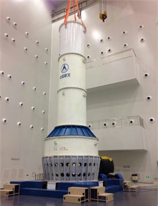
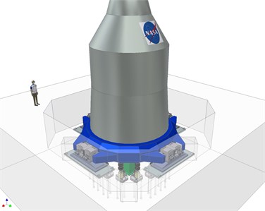
Fig. 7The largest multi-shaker facility of NASA
3.3. MIMO controller in large multi-shaker system
NASA has constructed one of largest multi-shaker sine test systems in the world. This new mechanical vibration facility is located at NASA Plum Brook in Sandusky Ohio. The multi shaker table will consist of 20 hydraulic actuators provided by Team Corporation. There are 16 vertical actuators 30 klbf rating, connected via friction-free double spherical couplings. There are 4 horizontal actuators.
Table 1Comparison between the above three solutions
No. | Solutions | Advantages | Disadvantages |
1 | Digital PCU | Capable of real-time loop control without calibration | Not suitable for random test |
2 | Analog PCU | Capable of performing sine and random test | Needed to be calibrated in advance |
3 | MIMO controller | Capable of performing sine and random test | Hydrostatic bearings are needed |
Data Physics was selected to provide the vibration controller for the new mechanical vibration facility. The controller is a Signal Star Matrix multi shaker sine control system with 64 inputs and 8 outputs.
This facility will be one of the largest multi-shaker sine test systems in the world. It will allow the Orion spacecraft to be mounted to the table and sequentially tested in all 3 axes without having to re-fixture the spacecraft. While the test objective is single axis vibration, a multi shaker controller is required to control the amplitude and phase of the control transducers using multiple drive signals. In addition to controlling the in-axis vibration, the controller must also cancel any cross axis or rotational vibration induced by load imbalance or structural resonance, in order to produce single axis motion. The controller must also be capable of both acceleration and force limiting to protect valuable flight hardware.
4. Conclusions
This paper summarizes three solutions to ensure the synchronization of multi-shakers by using the analog PCU, digital PCU or mimo-controller respectively to produce pure single axis motion. The test results show that different solutions have their own strength and weakness. They will play an important role in providing effective solutions for performing large spacecrafts’ vibration tests.
References
-
Alexandre Popovitch, “Multishaker upgrade at ESTEC, ESA,” in 22nd Aerospace Testing Seminar, Mar. 2005.
-
Pierre Touzelet, Alexandre Popovitch, and Gaetan Piret, “The ESTEC new quad head expander,” in 6th International Symposium on Environmental Testing for Space Programmes, pp. 12–14, 2007.
-
Keller T. and Underwood M. A., “An application of MIMO techniques to satellite testing,” in Institute of Environmental Sciences conference, 2001.
-
Underwood Marcos A., and Keller Tony, “Applying coordinate transformations to multi degree of free-dom shaker control,” in 74th Shock and Vibration Symposium, 2003.
-
D. O. Smallwood, “Multiple shaker random control with cross coupling,” in Combined Environments: Technology Interrelations, 1978.
-
M. Chen and D. Wilson, “The new triaxial shock and vibration test system at hill air force base,” Journal of the IEST, Vol. 41, No. 2, pp. 27–32, Mar. 1998, https://doi.org/10.17764/jiet.41.2.b105672q4732x30g
-
Peeters B. and Debille J., “MIMO random vibration qualification testing: algorithm and practical experiments,” Proceedings of ESTECH 2002, 2002.
-
M. A. Underwood, “Multi-exciter testing applications: theory and practice,” in Institute of Environmental Sciences conference, 2002.
-
Fan Shichao and Feng Yaoqi., “Study on Simulation test technology of dynamics environment of Multi-DOF,” Spacecraft Environment Engineering, Vol. 23, No. 1, pp. 23–28, 2006.
-
D. O. Smallwood, “Random vibration testing of a single test item with a multiple input control system,” in Institute of Environmental Sciences conference, pp. 42–49, 1981.
-
Qiu Hanping and Feng Yaoqi, “A new method for Dual-shaker sine vibration control,” (in Chinese), Spacecraft Environment Engineering, No. 6, pp. 355–358, 2006.
-
H. Qiu, Y. Feng, and Shichao Fan, “The application of coordinate transformation matrix into the multi-degree of freedom vibration control,” Vibroengineering Procedia, Vol. 10, pp. 266–271, 2016.
-
Liu Minghui, Wang Jian, and Gao Haiyang, “Application of FEA in structure design of large vibration test bed,” (in Chinese), Spacecraft Environment Engineering, Vol. 33, No. 3, pp. 257–261, 2016.
Cited by
About this article

