Abstract
The transmission of the high data rate and information over the optical fiber is restricted by various dispersion phenomenon which further results into intersymbol interference (ISI). This article proposes two different methodologies for optical fiber deformation aiding vibration monitoring one using the pin diode as a photo-detector device and another manifesting the avalanche photo-detector. The novelty of this article lies in optical signal conversion using photo-detector processing followed by low pass Gaussian filter in order to reduce the extra contortion. This work is approaching electronic dispersion compensation technique (EDC) for compensation of chromatic dispersion at two distinct bit rates of 25 and 30 Gbps over 120 km of single mode fiber. Both the diodes have tested for theory performance using factors like Q-factor, bit error rate and eye height. It is found that pin diode is exhibiting a quality factor of 67.150 and 40.5944 at 25 and 30 Gbps, respectively. When avalanche pin diode is used at the same data rates, quality factor of 73.0240 and 43.3523 are obtained, respectively. Hence, use of avalanche photodiode at high bit rates is utilized and the simulations showed the optimum photo-diode for efficacious dispersion compensation at such a long transmission distance.
Highlights
- This article finds out the usage of recognizable photo-detector devices at the receiver side in order to assess the Optical Fiber Deformation which can aid Vibration Monitoring.
- This article proposes two different methodologies for this purpose. One is utilization of pin diode as a photo-detector device and another is manifestation with avalanche photo-detector.
- The proposed framework fuses the transmitter section with continuous laser beam and NRZ along with Mach Zehnder modulator as signal propagated over longer distances needs modulation for result analysis.
- This article uses a novel approach of optical signal conversion using photo-detector processing for the signal received at the receiver section followed by low pass Gaussian filter in order to reduce the extra contortion.
- This novelty acts in providing the significantly better outcomes as the converted optical signal can easily travel down the optical fiber and it is again converted to electrical signal using photodiode at the receiver side.
- This article reveals that the avalanche photodiode can be considered better for optical fiber deformation aiding vibration monitoring comparative to the pin photodiode.
1. Introduction
Fiber obstacles like chromatic dispersion affect high speed optical fiber communication very badly. Thus, the system for transmission of signals should be carefully designed so that minimum distortion of signal occurs while propagating along the optical fiber. Presence of nonlinear factors requires more power, hence, fiber with little or non-zero chromatic dispersion is necessary for the coherent transmission over long distances. Existence of chromatic dispersion is predominant issue in single mode fibers as it deteriorates the signal up to a large extent. The result of this deterioration is popularly known as intersymbol interference (ISI). The transmission of the high data rate and information over the optical fiber is restricted by various dispersion phenomenon resulting into ISI.
Chromatic dispersion causes the pulse to be widened at the receiver. This occurs as different components of the pulses propagate at distinct velocities and arrives at receiver at distinct time intervals. This results into the loss of information over such a prolonged distance in long haul networks [1], [2]. This information loss is an irreversible process which limits the signal and degrades its quality. Distinct modules can be used for the compensation of the signal like dispersion compensating fibers and combination of one or more modules. This deterioration of the signals can have major impacts while signal is transmitted over long distances, hence reducing the transmission distances to a few Kilometers [3]. There are numerous alternatives present to resolve this hurdle of dispersion. Unlike other dispersion compensating procedures, electronic dispersion compensators (EDC) make use of non-linear and linear equalization approach. This methodology is an effectual, cost effective and compact dispersion compensating method.
1.1. Contribution
The major contribution of this research article lies in finding out the usage of recognizable photo-detector devices at the receiver side in order to assess the Optical Fiber Deformation which can aid Vibration Monitoring. This article proposes two different methodologies for this purpose. One is utilization of pin diode as a photo-detector device and another is manifestation with avalanche photo-detector. The proposed framework fuses the transmitter section with continuous laser beam and NRZ along with Mach Zehnder modulator as signal propagated over longer distances needs modulation for result analysis. This article uses a novel approach of optical signal conversion using photo-detector processing for the signal received at the receiver section followed by low pass Gaussian filter in order to reduce the extra contortion. This novelty acts in providing the significantly better outcomes as the converted optical signal can easily travel down the optical fiber and it is again converted to electrical signal using photodiode at the receiver side. This article reveals that the avalanche photodiode can be considered better for optical fiber deformation aiding vibration monitoring comparative to the pin photodiode.
The rest of this article is structures as: Section 2 provides the literature review of state-of-the-art methods followed by Section 3 presenting the material and experimental setup for the analysis. Section 4 provides the results and discussion followed by concluding remarks in Section 5.
2. Literature review
M.Y. Hamza et. al illustrated the compensation of dispersion by considering DCF as dispersion compensator in four distinct cases and then making the dispersion maps using Gaussian pulse. All the simulations performed at input powers form 3-10 dBm [4]. Lars Gruner-Nielsen et al. researched on three kinds of DCF which includes up gradation of non-shifted fibers and non-zero fibers, increases the probability of utilization of DCF [5]. M. Singh et al. observed the system performance at 10 Gbps for 150 km of SMF at pre, post and symmetric DCF and it is found that symmetric has superior performance in terms of quality factor. R. J. Nuyts et al. inspected the system performance using DCF at 10 Gbps over 360 km. Eye margin is increased to 48.5 % after compensation for the same BER of 10-15 which was 33.3 % before compensation [6], [7]. At the rate of 20 Gbps, three types of modulation techniques that are modified duobinary RZ, carrier suppressed RZ and duobinary RZ are simulated over 64 channels to provide a big capacity system of 1.28 Tbps in three schemes. Symmetric is found as the best using DCF as compensator but also got a tradeoff between spacing among the channels and distance enclosed. A.V. Patel et al. performed the simulation for a system with 40Gbps transmission rate over 4000 km. They showed a comparison among carrier suppressed RZ, differential PSK and modified duobinary RZ using DCF only for compensation and found DPSK to be the best performer in comparison to others at 0 dBm power in symmetrical scheme. For the same 40 Gbps rate and two distinct compensators i.e. DCF and FBG separately, another simulations performed in three configurations at a distance of 100 km. In both the cases, post scheme got the reward for best scheme [8]-[10].
A. N. Pilipetskii et al. showed that system performance can be improved upto more extent by using proper dispersion compensation methods instead of signal variance. S. Yhu showed the optical fibers and their dispersion range which normally exists 4-20 ps/nm/km. At a max of 60-300 km and 4-18 km distance can be covered at 10 and 40 Gbps, respectively, with no compensation [11], [12]. M. Sumetsky et al. provided an approach to eliminate group delay ripple with the help of using FBG along with its fabrication techniques. CFBG provides a facility of dispersion tuning not available in standard DCF’s, thereby, making it better for OTDM and WDM systems. James F. Brennan III also focused on problems occurs while utilizing FBG as dispersion compensator [13], [14]. A. B. Dar et al. explained all the major techniques for compensation of dispersion along with changing the various apodization profiles for FBG. Tanhapodized profile got better results, thus, making FBG better technique [15]. W. Chen et. al provided a system using DCM instead of DCF as dispersion compensator for 48channels at 40 Gbps data rate and providing a better slope compensation than DCF [16]. G. Gnanagurunathan et al. showed FBG as better technique than DCF for a four-channel system varying its bit rates from 2.5 to 40 Gbps over 600 km transmission distance. H.S. Fews et al. compared DCF and FBG for 40 channels at 10 Gbps rate over 525 km distance and found FBG as superior dispersion compensator. K. Khairi et al. also compared DCF with MC-CFBG at 10 Gbps rate over 100 km transmission distance and concluded MC-CFBG as superior than DCF [17], [18], [19]. K. O. Hill et al. provided fabrication of CFBG using novel double exposure method for dispersion compensation in 1549 nm window using a grating of 3 cm. Natalia M. Litchinitser et al. showed that a maximum of 100 km and 400 km distance can be achieved with a grating of 10cm and 20 cm, respectively using apodized CFBG for WDM applications [20], [21]. D. Garthe et. al. used adjustable equalizers for two distances of 80 km and 160 km at 10, 20 Gbps data rates, respectively and got a compensation of up to 80 km for 20G bps transmission rate and 160 km for 10 Gbps bit rate. B. J. Eggleton et al. showed the importance of grating in dispersion compensation by utilizing a 11 cm grating at 10 Gbps rate and achieved a distance of 72 km with no power penalty but for the distance of 160 km, 2 dB power penalty existed at the same rate even with the use of compensator [22], [23]. W. H. Loh et al. showed that almost 100 km distance can be achieved without compensation at 10 Gbps rate but from 100-400 km, 10 cm CFBG used in pre configuration. Grating was shifted to the centre section of transmission link, for the further lossless transmission of up to 700 km [24]. A. H. Gnauck et al. evaluated the dispersion compensation for 8 channels at two rates of 10 and 20 Gbps over 480 and 315 km distances, respectively. They have shown that for a WDM system of 8×10 Gbps, six gratings and for 8×20 Gbps, four gratings are sufficient to get the perfect outcomes [25]. Isabelle Riant et. al used DCG for compensation and showed that dispersion can be compensated up to 80 km for four channels and upto 400 km for two channels at 10Gbps transmission rate [26]. L. D. Garrett et. al performed dispersion compensation on a WDM system consisted of 16 channels at 10 Gbps over 840 km by using eleven CFBG. Ten gratings were provided with dispersion of –1330 ps whereas the last one is provided with an extra slope of –35ps. Even the worst case of compensation exhibited a quality factor of 16.9 dB with bit error rate of 1.3 ×10⁻¹² [27]. L.D. Garrett et. al utilized two distinct modules at 10 Gbps rate for 32 channels over 375 km distance. One is having two gratings in cascade and other is having a single grating. 32 channels were divided into three categories of upper red band, lower red band and blue band. Hence, a mean quality factor of 19.8 dB is obtained for upper red band and blue band whereas it is 20.2 dB for lower red band [28]. L. Pei et al. analyzed a 13 channel system at 10 Gbps over 3100 km for three distinct pulse generators that are RZ, NRZ and carrier suppressed RZ and found that CSRZ is the finest option for communication with lower power penalty than others [29]. L. Zhu et al. used specially sampled fiber Bragg grating in place of CFBG and found that pre configuration is superior at 10 Gbps rate over 1000 km. Also, CFBG got better results in post configuration when compared with SSFBG [30]. B. J. Eggleton et al. produced a tunable dispersion compensator using CFBG for a TDM system at a transmission rate of 160 Gbps which reduced dispersion to a level at a lower power penalty equals to 1.3 dB [31].
IS Amiri et al. used a module of fiber grating and emulator together for compensation of dispersion by using an optical fiber of 10-250 km at 10-600 Gbps rate. The maximum SNR obtained is 69 dB, with an output OSNR = 65 dB and 126 dB gain. Peng Xia et. al. provided a study of dispersion compensation using IDCFBG at a fixed transmission rate of 10 Gbps over a distance of 50 km. The study was carried out by using IDCFBG in three models of pre compensation, post compensation and symmetrical compensation. The authors concluded that symmetrical configuration is performing best under the given conditions [32], [33].
T. Adali et al. showed the utilization of electronic equalizers based on MMSE criterion. A direct mean pulse is applied which is non-zero and then determination of pulse properties on eigen value of that pulse is done so that its outcomes can be applied to MMSE equalization. PMD is mitigated using two kinds of MMSE equalizers i.e. FFE with 7 taps and DFE with 5 forward and 3 feedback taps [34]. M. Seiben et. al investigated a system which used optical single band transmission instead of double sideband transmission at 10 Gbps rate and 320 km transmission distance over non dispersion shifted fibers by utilizing electronic dispersion compensator for compensation of dispersion. Minimum error of 10-10 was achieved for the specified distance. They showed that single band transmission with equalization can go beyond 600 km if modulator’s drive level is properly chosen [35]. A. C. Singer et al. tested for receiver utilizing MLSE for compensation of dispersion at 10 Gbps rate up to 200 km and got a BER of 10-4 [35]. M. Moghaddasi et al. showed a balancing of OOK RZ and NRZ modulation scheme, firstly using FFE-DFE equalizer and then DCF at 10 Gbps rate over a varying distance of 70-160 km and found that NRZ performed best in electrical equalizers but for shorter distances, RZ can be applied in optical compensation [36]. Y. Ma et al. demonstrated the use of EDC for compensation of dispersion at definite bit rates of 50-80 Gbps by utilizing two types of diodes at the receiver- pin photodiode and avalanche photodiode. The author concluded that avalanche photodiode is giving better results as compared to pin diode under given conditions [37].
Hence, it has become necessary to utilize any compensation technique for the smooth and non-interrupted transmission. So, for this compensation, digital filters, EDC technique, FBG and dispersion compensating fibers techniques and are most commonly used techniques. The literature review of various methodologies in this domain is done in Table 1.
3. Material and methods
The literature suggests that there are various types of losses which occur for Optical Fiber Deformation and Vibration Monitoring. This article uses the technique of equating the positive and negative dispersion over the fiber length is utilized, known as dispersion management, to overcome the losses. The overall dispersion is either zero or within the sustainable limit, when the signal arrives at recipient. Also, it is inversely corresponding to the square of the signal’s information rate. Approximately a chromatic dispersion of 17 ps/km/nm is normally exhibited by single mode fibers and also have minimal attenuation when operates around a wavelength of 15550 nm.
In order to model the overall reverberations of group velocity dispersion, loss and self-phase modulation, non-linear Schrodinger equation can be used shown below in Eq. (1):
where, – amplitude of the pulse varying at slow rate, – attenuation, , – governing the effect of non-linearity and dispersion, – reference frame propagating with the signal at group velocity.
In the Eq. (1), split step Fourier method has been used to solve it. Further, for its implementation, length of the fiber is portioned into many segments. The optical signal is propagated segment wise.
3.1. Methods for dispersion compensation
3.1.1. Dispersion compensating fibers
Use of DCF for compensation was first proposed in late 1980s. It is because of its some features like more stability towards change in temperature and broad bandwidth. It operates on the theory of negative dispersion, where, positive dispersion of SMF is cancelled by its negative value. Hence, the overall dispersion becomes close to zero in the signal propagating along the fiber.
Table 1Literature review of various methodologies in this domain
Literature reviewed | Concept | Challenges | Technologies popular solutions available | Conclusion |
I. Amiri, A. Nabih Zaki Rashed, H. M. Abdel Kader, A. A. Al-Awamry, I. A. Abd El-Aziz, P. Yupapin, G. Palai [32] | Dispersion Compensation-both intermodal and polarisation mode dispersion | Chromatic and polarisation mode dispersion compensation over 250 km long optical fiber | FBG and Emulator | The max. Value of output signal to noise ratio reached to 69 dB whereas output offset signal to noise ratio reached to 65 dB and gain of 126 dB has been observed. |
P. Xia, Z. Li-Hua, Y. Lin [33] | Chromatic Dispersion Compensation | Compensation of dispersion at a transmission rate of 10 Gbps for 50 km transmission | FBG-post, symmetrical & pre and compensation | Symmetrical compensation is performing better than other two. |
A. Sharma, I. Singh, S. Bhattacharya [42] | Mitigation of chromatic dispersion using Hybrid model | Compensation of dispersion at 100 Giga bits per second over a single mode fiber of 120 km | Using UFBG with EDC | Q-Factor sharply increased to 37.12 from 14.48 when power is increased from 1-10 dBm |
S. Sharma, A. Sharma, S. Thakur [48] | Chromatic dispersion compensation using EDC | Compensation of dispersion using EDC at 20.25 and 30 Gbps for a length of 120 km | EDC technique | A maximum increase of Q-Factor of 40 ha been observed before and after equalization. |
Y. Ma, Q. Chen, S. Wang, S. Sharma, S. Khanna [37] | To compensate the chromatic dispersion and comparison between pin photo and avalanche photodiode | Chromatic dispersion compensation at 50–80 Gbps for 120 km of transmission distances. | UFBG and EDC module | Avalanche photodiode is giving finer results than pin photo-diode at 50-80 Gbps transmission rates. |
Range of negative dispersion for dispersion compensating fiber is from –70 to –90 ps/nm/km [38]. Hence, overall dispersion and attenuation of any optical link can be described by using Eq. (2), (3):
where, and – single mode fibers length and dispersion, respectively, and – dispersion compensating fibers length and dispersion, respectively.
Another concept of figure of merit is given by Eq. (4) given below:
If length of the DCF is chosen in a way that total dispersion is equals to zero, then the overall loss can be determined form Eqs. (2), (3) and (4):
Thus, it can be concluded that extra attenuation due to DCF can be calculated by figure if merit only.
The residual dispersion of the channel after then – segment compensation of dispersion compensating fibers is given in Eq. (6):
where, – -channel compensation rate [39].
3.1.2. Fiber Bragg grating
Normally, no optical fiber suffers from change in the refractive index of core and cladding along its length. Fiber Bragg grating exhibits the characteristic of varying refractive indices of cladding and core along the length of the fiber which causes scattering of the travelling pulse [29], [40]. Grating can be chirped, uniform and superstructure. These are differentiated on the basis of grating period. As the name says, uniform grating has fixed grating period whereas chirped grating flaunts variation in refractive indexes. Distinct wavelengths reflect at distinct positions and thereby, resulting into distinct time delays [41], [42].
Let and be the refractive index of and cladding, by assuming step index fiber and of single cladding. For both the modes, electrical field in the core domain is given in the Eq. (7) shown below:
where, = th order Bessel function, and – constants (normalized), – mode number of cladding, – dispersion relation formula.
Remaining variables can be defined as in Eq. (9) given below:
From this distribution of fields, coupling constant can be determined. These equations can be then solved by utilizing mathematical analysis. After evaluating, the equations for FBG can be explained as Eq. (10) given below:
where, – coupling coefficient between two modes and , – phase mismatch between forward-backward modes.
Let us assume FBG length = l, then:
Hence, the coefficient of refraction will be:
So, the final response of FBG would be as described in Eq. (13) given below [43]:
3.1.3. Electronic dispersion compensation
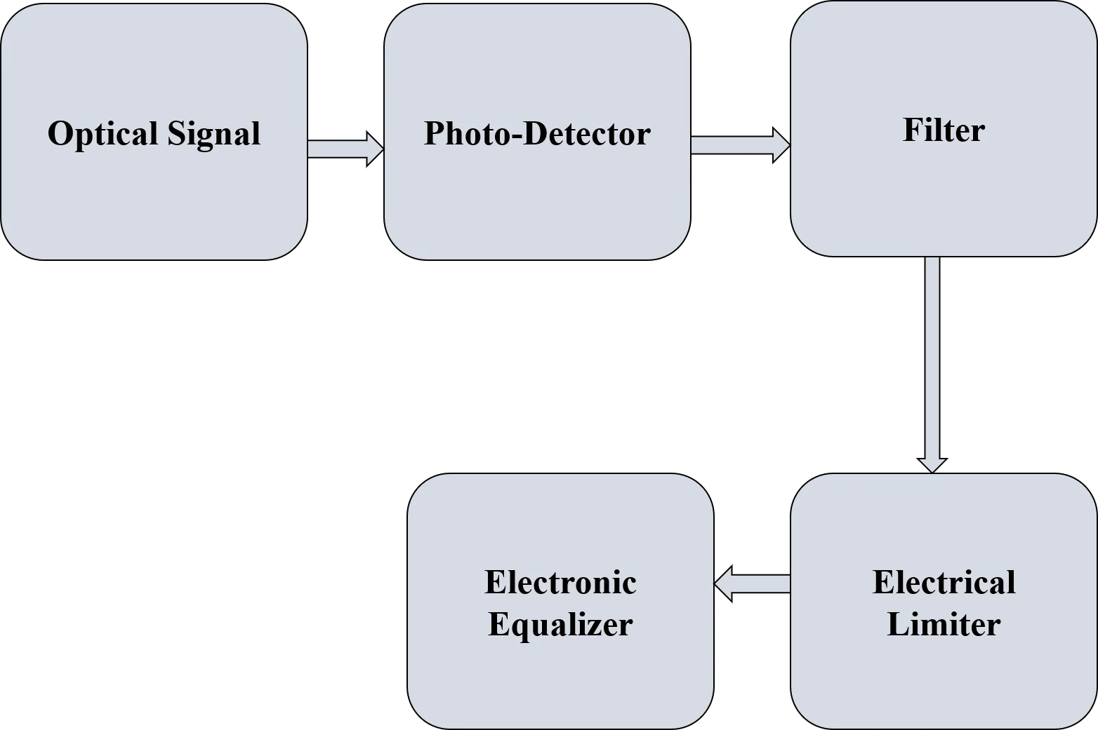
This method uses electronics in coexistence with optics for the compensation of dispersion in fiber optics either chromatic dispersion or polarization mode dispersion. Two ways are present in which EDC can be utilized for compensation. In first way, first order PMD inside the fiber can be compensated by abandoning out it with the complementary PMD made at recipient. Another way of compensation is to make use of equalization circuits which is the most frequent method of compensation [44]-[46]. Fig. 1 is representing the simple block diagram of any electronic equalizer. Various techniques are present for using the electronic equalizer that are feedforward equalizers, feedback equalizers and maximum likelihood sequence estimator. Alleviation of dispersion is normally done in optical field before its detection at recipient but the electronic dispersion compensator makes use of electronics for this motive.
Fig. 1Basic Representation of electronic equalizer
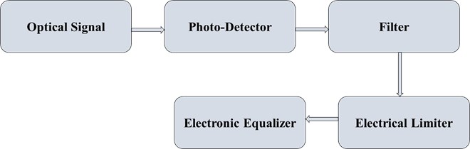
Two distinct strategies are available for its implementation are direct detection technique and optical heterodyne detection method. Optical detection technique makes use of feed forward equalizer [47]-[49].
Any feed forward equalizers exhibits output specified in Eq. (14) as shown below:
where, – value of the pulse at t time interval, – gross no. of taps in FFE.
3.2. Experimental setup for design and simulation of optical link
The vital goal of this research is to find out and discover the end results of using recognizable photo-detector devices at the receiver side. In order to reach to consequences, two different models have been proposed for optical fiber deformation aiding vibration monitoring. Out of them, one is utilizing pin diode as a photo-detector device and another is manifesting with avalanche photo-detector. Three main parts has been included during designing of the optical link-transmitter part, optical communication path and recipient part. The transmitter section is fused with continuous laser beam and NRZ along with Mach Zehnder modulator as signal propagated over longer distances needs modulation. Getting signal at the receiver section is fulfilled by photo-detector first and then purify by low pass Gaussian filter in order to reduce the extra contortion. Whole simulation is done at 120 km distance for 25 and 30 Gbps bit rates, respectively presuming the input power varying from 1-10 dBm. Variables required for the even simulation are described in tabular form. EDC used for dispersion compensation has its parameters tabulated in Table 2. Table 3 is depicting the normalized parameters for the simulation including standard frequency and transmission rate for communication whereas simulation parameters of single mode fibers are shown in Table 4.
Table 2EDC simulation parameters
Parameters | Value |
Forward tap coefficients | 3 |
Forward tap space | 5 |
Leakage factor | 1 |
Step size | 0.3 |
Feedback tap coefficients | 2 |
Table 3Normalized simulation parameters
Parameters | Value |
Bandwidth | 1 THz |
Frequency | 193.1 THz |
Bit rate | 25 and 30 Gbps |
Table 4SMF simulation parameters
Parameters | Value |
Attenuation | 0.2 db/km |
Differential group delay | 3 ps/km |
Dispersion | 0.01 ps/nm/km |
Length | 120 km |
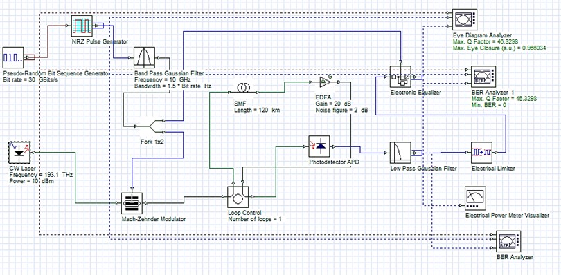
Along with the tables, simulation setups for two distinct cases are also shown in the form of figures. Fig. 2 is depicting use of pin diode at receiver along with EDC for dispersion compensation whereas use of avalanche photo diode is displayed in Fig. 3.
A comparison has been done between both the cases to determine the unbeatable photo-detector at receiver in order to enhance the signal quality and to get better Q-factor with minimal bit error rate.
Fig. 2Experimental simulation setup for dispersion compensation using EDC with pin diode photo-detector
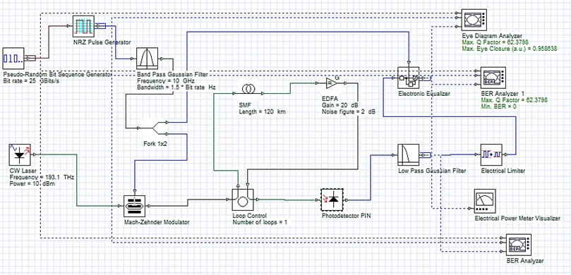
Fig. 3Experimental simulation setup for dispersion compensation using EDC with avalanche pin diode
4. Results and discussions
Multiple parameters are available to determine the impact of dispersion on the existing optical link design but simulations of all the parameters at a specified time period is not possible. This research paper focuses on optical fiber deformation aiding vibration monitoring by changing a specific device used at receiver to analyze the changes that has been occurred. Whatever changes happens, they all are observed by their respective eye diagrams. Initially, to get the optical pulse at the receiver and then transforming back into electrical signal, PN diode has been used. Apart from the pin diode, another dispersion compensator called EDC is used. Pin diode is configured at transmission rates of 25 and 30 Gbps, respectively by holding on the parameters of compensator to a fixed value for both transmission rates. Reenactments have been done and the results are investigated in eye diagram form. Every one of the simulations have been finished by changing the input power from 1-10 dBm.
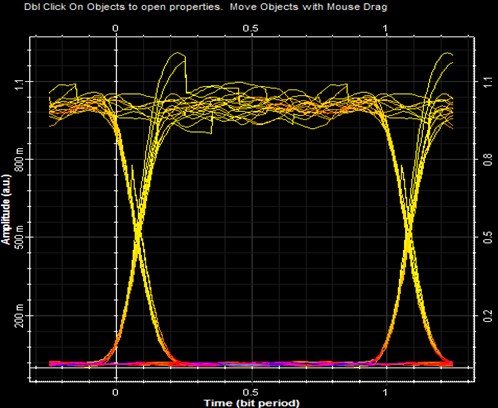
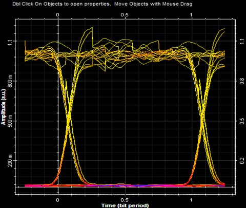
Fig. 4 is showing the eye diagram having PN diode as photo-detector device at 25 Gbps whereas eye diagram at a bit rate of 30 Gbps is displayed in Fig. 5. As the input power value is diversified from 1-10 dBm, but eye diagrams of only maximum power is shown, that is, 10 dBm as they are getting the highest level outcome at 10 dBm power at best. The same kind of procedure has been implemented by considering into account another popular photo-detector i.e. avalanche pin-diode for transformation at recipient. Its end results are analyzed at two transmission rates of 25 and 30 Gbps and then unveiled diagrammatically using eye diagrams at highest power of 10 dBm. Fig. 6 is displaying the eye diagram of avalanche pin-diode at 25 Gbps whereas Fig. 7 is showing the eye diagram same photo-detector device at 30 Gbps. The concluding step shows the comparison of PN and avalanche photodiodes and drawn the best between them.
Fig. 4Eye diagram using pin-diode at 25 Gbps
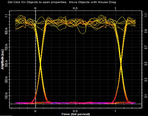
Fig. 5Eye diagram using pin-diode at 30 Gbps
As it can be seen from the eye diagrams, avalanche pin-diode at 25 Gbps is exhibiting the maximum eye opening when compared with pin diode at 25 and 30 Gbps. Maximum eye-opening leads to minimal distortion and dispersion at the receiver which is the necessary part of any kind of optical communication link. Hence, it can be concluded that avalanche pin diode is performing its best at 25 Gbps rate when compared with pin photo-diode at the same rate.
Fig. 6Eye diagram using avalanche pin-diode at 25 Gbps
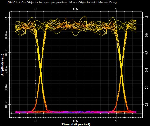
Fig. 7Eye diagram using avalanche pin-diode 30 Gbps
Apart from analyzing the eye diagrams, other parameters are also there which determined the optimal photo-detector device. This includes comparison of both the devices in terms of eye height, quality- factor and bit error rate.
Comparisons of result determining parameters are shown graphically. Fig. 8 and Fig. 9 are showing the Q-factor comparison using avalanche and pin photodiode at 25 and 30 Gbps rates, respectively whereas comparison of bit error rates is also displayed in graphical form in Fig. 10 and Fig. 11 for 25 and 30 Gbps, respectively. Another comparison of eye height is done at 25 and 30 Gbps for both types of diodes and displayed in Fig. 12 and Fig. 13, respectively. After observing the comparison graphs, distinct points can be derived. Q-factor of avalanche diode reaches at a maximum of 73.0240 and 43.3523 whereas pin photodiode is having a q-factor of 67.150 and 40.5944 at 25 and 30 Gbps rates. When bit error rate is compared, it is giving a mixed result for both the diodes. The comparative analysis of quality factors at both the bit rates is defined in Tabular form in Table 5. At the ending, it can be said that it provides the optimal overall performance using avalanche pin diode at 25 and 30 Gbps transmission rates and 120 km using single mode fiber.
Fig. 8Q-factor comparison at 25 Gbps
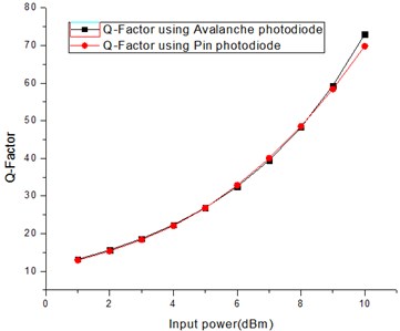
Fig. 9Q-factor comparison at 30 Gbps
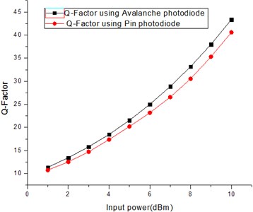
Fig. 10BER comparison at 25 Gbps
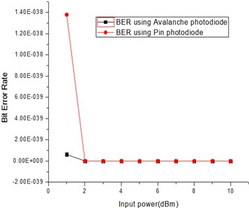
Fig. 11BER comparison at 30 Gbps
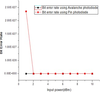
Fig. 12Eye height at 25 Gbps
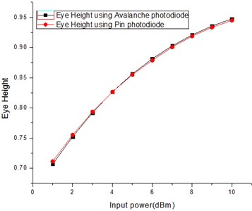
Fig. 13Eye height at 30 Gbps
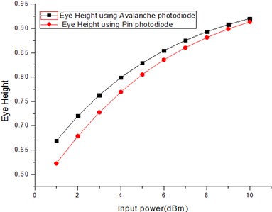
Table 5Comparative analysis
Bit rates (in Gbps) | Q-Factor | |
Pin photodiode | Avalanche photodiode | |
25 | 67.150 | 73.0240 |
30 | 40.5944 | 43.3523 |
5. Conclusions
This article proposes a framework for optical fiber deformation aiding vibration monitoring using recognizable photo-detector devices at the receiver side of photo detectors. The work in this paper basically focuses on extracting the optimal photo detector to be used at receiver in order to get the highest q-factor and minimal bit error rate. The performance of the two photo-detectors has been analyzed by simulating them at two distinct bit rates of 25 and 30 Gbps. Their outcomes are analyzed by observing their quality factor, bit error rate and eye height and then comparing them at both data rates using single mode fiber at 120 km. It is found that pin diode is exhibiting a quality factor of 67.150 and 40.5944 at 25 and 30 Gbps, respectively. When avalanche pin diode is used at the same data rates, quality factor of 73.0240 and 43.3523 are obtained, respectively. Similarly, overall bit error rate at these two rates is minimal using avalanche pin diode when compared with pin photodiode. By comparing these factors, an important conclusion has been drawn such that at both transmission rates, avalanche pin diode performing better than pin photo-detector. This is the most important conclusion as normally pin diode tops the avalanche pin diode in most of the systems. Finally, the conclusion favors the utilization of avalanche pin diode at 25 and 30 Gbps rates over 120 km transmission distance using electronic dispersion compensator for dispersion compensation for getting dispersion free signal.
References
-
Ashwani Sharma, Inder Singh, and Suman Bhattacharya, “Performance analysis of dispersion reparation using dispersion compensation fiber at 100 Gb/S for 120km using single mode fiber,” Zenodo, Vol. 7, No. 2, pp. 513–523, Feb. 2018, https://doi.org/10.5281/zenodo.1173579
-
S. Chandramouli, F. Bien, H. Kim, C. Scholz, E. Gebara, and J. Laskar, “10 Gbps optical fiber transmission using a fully analog electronic dispersion compensator (EDC) with unclock decision feedback equalization,” IEEE Transaction on Microwave Theory and Techniques, Vol. 55, No. 12, pp. 2740–2746, Dec. 2007.
-
Z. Yang, L. Yi, J. Ke, Q. Zhuge, Y. Yang, and W. Hu, “Chaotic optical communication over 1000 km transmission by coherent detection,” Journal of Lightwave Technology, Vol. 38, No. 17, pp. 4648–4655, Sep. 2020, https://doi.org/10.1109/jlt.2020.2994155
-
M. Hamza, S. Tariq, and L. Chen, “Dispersion compensation in the presence of nonlinearity in optical fiber communications,” in 2006 10th IEEE Singapore International Conference on Communication Systems, 2006, https://doi.org/10.1109/iccs.2006.301421
-
L. Grüner-Nielsen et al., “Dispersion compensating fibers,” Optical Fiber Technology, Vol. 6, No. 2, pp. 164–180, Apr. 2000, https://doi.org/10.1006/ofte.1999.0324
-
R. Kaur and M. Singh, “Dispersion compensation in optical fiber communication system using WDM with DCF and FBG,” IOSR Journal of Electronics and Communication Engineering, Vol. 11, No. 2, pp. 122–130, 2016, https://doi.org/10.9790/2834-110302122130
-
R. J. Nuyts, Yong Kwan Park, and P. Gallion, “Dispersion equalization of a 10 Gb/s repeatered transmission system using dispersion compensating fibers,” Journal of Lightwave Technology, Vol. 15, No. 1, pp. 31–42, 1997, https://doi.org/10.1109/50.552111
-
B. Patnaik and P. K. Sahu, “Ultra high capacity 1.28 Tbps DWDM system design and simulation using optimized modulation format,” Optik, Vol. 124, No. 13, pp. 1567–1573, Jul. 2013, https://doi.org/10.1016/j.ijleo.2012.04.019
-
A. V. Patel, R. B. Patel, and K. A. Mehta, “Comparative analysis of single span high speed 40 Gbps long haul optical link using different modulation formats in the presence of Kerr nonlinearity,” in 2014 IEEE Students' Technology Symposium (TechSym), pp. 132–137, Feb. 2014, https://doi.org/10.1109/techsym.2014.6807928
-
S. Kumar, “Performance analysis of dispersion compensation in long haul optical fiber with DCF,” IOSR Journal of Electronics and Communication Engineering, Vol. 6, No. 6, pp. 19–23, 2013, https://doi.org/10.9790/2834-0661923
-
A. N. Pilipetskii, V. J. Mazurczyk, and C. J. Chen, “The effect of dispersion compensation on system performance when nonlinearities are important,” IEEE Photonics Technology Letters, Vol. 11, No. 2, pp. 284–286, Feb. 1999, https://doi.org/10.1109/68.740731
-
Shi Yuhu, “Research on the dispersion problem in high speed optical communication systems,” in 2011 2nd International Conference on Artificial Intelligence, Management Science and Electronic Commerce (AIMSEC), pp. 4742–4745, Aug. 2011, https://doi.org/10.1109/aimsec.2011.6010342
-
M. Sumetsky and B. J. Eggleton, “Fiber Bragg gratings for dispersion compensation in optical communication systems,” in Ultrahigh-Speed Optical Transmission Technology, Berlin, Heidelberg: Springer Berlin Heidelberg, 2005, pp. 277–299, https://doi.org/10.1007/978-3-540-68005-5_10
-
D. Kumar, A. Sharma, R. Kumar, and N. Sharma, “Restoration of the network for next generation (5G) optical communication network,” in 2019 International Conference on Signal Processing and Communication (ICSC), Mar. 2019, https://doi.org/10.1109/icsc45622.2019.8938337
-
A. B. Dar and R. K. Jha, “Chromatic dispersion compensation techniques and characterization of fiber bragg grating for dispersion compensation,” Optical and Quantum Electronics, Vol. 49, No. 3, pp. 1–35, Mar. 2017, https://doi.org/10.1007/s11082-017-0944-4
-
W. Chen, S. Li, P. Lu, D. Wang, and W. Luo, “Dispersion compensation optical fiber modules for 40 Gbps WDM communication systems,” Frontiers of Optoelectronics in China, Vol. 3, No. 4, pp. 333–338, Dec. 2010, https://doi.org/10.1007/s12200-010-0117-6
-
G. Gnanagurunathan and F. A. Rahman, “Comparing FBG and DCF as dispersion in the long haul narrowband WDM systems,” in 2006 IFIP International Conference on Wireless and Optical Communications Networks, 2006, https://doi.org/10.1109/wocn.2006.1666665
-
H. S. Fews, M. F. C. Stephens, A. Straw, W. Forysiak, B. K. Nayar, and L. M. Gleeson, “Experimental comparison of fibre and grating-based dispersion compensation schemes for 40 channel 10 Gb/s DWDM systems,” in 2006 32nd European Conference on Optical Communications – (ECOC 2006), Sep. 2006, https://doi.org/10.1109/ecoc.2006.4800994
-
K. Khairi, Z. Lambak, N. Md Samsuri, Z. Hamzah, and F. Kok Hann, “Investigation on the performance of pre – and post compensation using multi-channel CFBG dispersion compensators,” in 2011 IEEE International RF and Microwave Conference (RFM), pp. 254–257, Dec. 2011, https://doi.org/10.1109/rfm.2011.6168742
-
K. O. Hill et al., “Chirped in-fiber Bragg gratings for compensation of optical-fiber dispersion,” Optics Letters, Vol. 19, No. 17, p. 1314, Sep. 1994, https://doi.org/10.1364/ol.19.001314
-
Natalia Litchinitser, “Fiber Bragg gratings for dispersion compensation in transmission: theoretical model and design criteria for nearly ideal pulse recompression,” IEEE/OSA Journal of Lightwave Technology, Vol. 15, No. 8, pp. 1303–1313, 1997.
-
D. Garthe, R. E. Epworth, W. Lee, and A. Hadjifotiou, “Adjustable dispersion equalizer for 10 and 20 Gbps over distances upto 160km,” Electronics letter, Vol. 30, No. 25, pp. 2159–2160, 1994.
-
B. J. Eggleton, T. Stephens, P. A. Krug, G. Dhosi, Z. Brodzeli, and F. Ouellette, “Dispersion compensation using a fibre grating in transmission,” Electronics Letters, Vol. 32, No. 17, pp. 1610–1611, 1996, https://doi.org/10.1049/el:19961027
-
W. H. Lob, R. I. Laming, A. D. Ellis, and D. Atkinson, “10 Gb/s transmission over 700 km of standard single-mode fiber with 10-cm chirped fiber grating compensator and duobinary transmitter,” IEEE Photonics Technology Letters, Vol. 8, No. 9, pp. 1258–1260, Sep. 1996, https://doi.org/10.1109/68.531855
-
A. H. Gnauck, L. D. Garrett, F. Forghieri, V. Gusmeroli, and D. Scarano, “8×20 Gb/s 315-km, 8×10 Gb/s 480-km WDM transmission over conventional fiber using multiple broad-band fiber gratings,” IEEE Photonics Technology Letters, Vol. 10, No. 10, pp. 1495–1497, Oct. 1998, https://doi.org/10.1109/68.720306
-
I. Riant, S. Gurib, J. Gourhant, P. Sansonetti, C. Bungarzeanu, and R. Kashyap, “Chirped fiber Bragg gratings for WDM chromatic dispersion compensation in multispan 10-Gb/s transmission,” IEEE Journal of Selected Topics in Quantum Electronics, Vol. 5, No. 5, pp. 1312–1324, 1999, https://doi.org/10.1109/2944.806756
-
L. D. Garrett, A. H. Gnauck, F. Forghieri, V. Gusmeroli, and D. Scarano, “16×10 Gb/s WDM transmission over 840-km SMF using eleven broad-band chirped fiber gratings,” IEEE Photonics Technology Letters, Vol. 11, No. 4, pp. 484–486, Apr. 1999, https://doi.org/10.1109/68.752556
-
L. D. Garrett et al., “Cascaded chirped fiber gratings for 18-nm-bandwidth dispersion compensation,” IEEE Photonics Technology Letters, Vol. 12, No. 3, pp. 356–358, Mar. 2000, https://doi.org/10.1109/68.826939
-
H. Sun, M. Fan, and A. Sharma, “Design and implementation of construction prediction and management platform based on building information modelling and three‐dimensional simulation technology in industry 4.0,” IET Collaborative Intelligent Manufacturing, Mar. 2021, https://doi.org/10.1049/cim2.12019
-
Y. Liu, Q. Sun, A. Sharma, A. Sharma, and G. Dhiman, “Line monitoring and identification based on roadmap towards edge computing,” Wireless Personal Communications, Feb. 2021, https://doi.org/10.1007/s11277-021-08272-y
-
X. Ren et al., “Design of multi-information fusion based intelligent electrical fire detection system for green buildings,” Sustainability, Vol. 13, No. 6, p. 3405, Mar. 2021, https://doi.org/10.3390/su13063405
-
I. Amiri et al., “Optical communication transmission systems improvement based on chromatic and polarization mode dispersion compensation simulation management,” Optik, Vol. 207, p. 163853, Apr. 2020, https://doi.org/10.1016/j.ijleo.2019.163853
-
P. Xia, L.-H. Zhang, and Y. Lin, “Simulation study of dispersion compensation in optical communication systems based on optisystem,” Journal of Physics: Conference Series, Vol. 1187, No. 4, p. 042011, Apr. 2019, https://doi.org/10.1088/1742-6596/1187/4/042011
-
T. Adali, Wei Wang, and A. O. Lima, “Electronic equalization in optical fiber communications,” in International Conference on Acoustics, Speech and Signal Processing (ICASSP'03), pp. 497–500, Nov. 2003, https://doi.org/10.1109/icassp.2003.1202688
-
M. Sieben, J. Conradi, and D. E. Dodds, “Optical single sideband transmission at 10 Gb/s using only electrical dispersion compensation,” Journal of Lightwave Technology, Vol. 17, No. 10, pp. 1742–1749, 1999, https://doi.org/10.1109/50.793744
-
M. Poongodi, A. Sharma, M. Hamdi, M. Maode, and N. Chilamkurti, “Smart healthcare in smart cities: wireless patient monitoring system using IoT,” The Journal of Supercomputing, Apr. 2021, https://doi.org/10.1007/s11227-021-03765-w
-
Y. Ma, Q. Chen, S. Wang, S. Sharma, and S. Khanna, “Research on dispersion compensation using avalanche photodiode and pin photodiode,” IET Collaborative Intelligent Manufacturing, Dec. 2020, https://doi.org/10.1049/cim2.12000
-
M. Moghaddasi and S. B. A. Rahman, “Comparison between NRZ and RZ OOK modulation format in chromatic dispersion compensation in both electrical and optical compensator,” in 2011 IEEE Symposium on Business, Engineering and Industrial Applications (ISBEIA), pp. 494–497, Sep. 2011, https://doi.org/10.1109/isbeia.2011.6088865
-
Martin Guy et al., “Novel applications of fiber Bragg grating components for next-generation WDM systems,” Annales Des Télécommunications, Vol. 58, No. 9, pp. 1275–1306, Sep. 2003, https://doi.org/10.1007/bf03001732
-
Y. Wang et al., “An exhaustive research on the application of intrusion detection technology in computer network security in sensor networks,” Journal of Sensors, Vol. 2021, pp. 1–11, May 2021, https://doi.org/10.1155/2021/5558860
-
D. Kumar, A. Sharma, R. Kumar, and N. Sharma, “A holistic survey on disaster and disruption in optical communication network,” Recent Advances in Electrical and Electronic Engineering (Formerly Recent Patents on Electrical and Electronic Engineering), Vol. 13, No. 2, pp. 130–135, Apr. 2020, https://doi.org/10.2174/2352096512666190215141938
-
G. E. Y. Teng, “Broadband dispersion compensation technology in high speed optical fiber communication systems,” International Journal of Simulation: Systems, Science and Technology, Vol. 18, pp. 01–8, Jan. 1970, https://doi.org/10.5013/ijssst.a.17.01.18
-
A. Sharma, I. Singh, S. Sharma, and S. Bhattacharya, “Analyzing dispersion compensation using UFBG at 100gbps over 120km using single mode fiber,” International Journal of Mechanical Engineering and Technology (IJMET), Vol. 8, No. 12, pp. 1075–1082, Dec. 2017.
-
L. Pei et al., “Dispersion compensation of fiber Bragg gratings in 3100 km high speed optical fiber transmission system,” Frontiers of Optoelectronics in China, Vol. 2, No. 2, pp. 163–169, Jun. 2009, https://doi.org/10.1007/s12200-009-0037-5
-
X. Xu, L. Li, and A. Sharma, “Controlling messy errors in virtual reconstruction of random sports image capture points for complex systems,” International Journal of System Assurance Engineering and Management, pp. 1–8, Apr. 2021, https://doi.org/10.1007/s13198-021-01094-y
-
G. Katz, D. Sadot, and J. Tabrikian, “Electrical dispersion compensation equalizers in optical direct – and coherent-detection systems,” IEEE Transactions on Communications, Vol. 54, No. 11, pp. 2045–2050, Nov. 2006, https://doi.org/10.1109/tcomm.2006.884846
-
S. S. Shalini Sharma, “Comparative analysis of dispersion compensation using electronic dispersion compensation techniques at different bit rates using single mode fiber,” International Journal of Mechanical and Production Engineering Research and Development, Vol. 8, No. 3, pp. 365–374, 2018, https://doi.org/10.24247/ijmperdjun201840
-
Valts Dilendorfs, Sandis Spolītis, and Vjačeslavs Bobrovs, “Effectiveness evaluation of dispersion compensation methods for fiber-optical transmission systems,” in 2016 Progress in Electromagnetics Research Symposium (PIERS 2016 Shanghai): Proceedings, pp. 3759–3763, 2016.
-
M. Fan and A. Sharma, “Design and implementation of construction cost prediction model based on SVM and LSSVM in industries 4.0,” International Journal of Intelligent Computing and Cybernetics, Vol. 14, No. 2, pp. 145–157, Apr. 2021, https://doi.org/10.1108/ijicc-10-2020-0142
About this article

Humanities and social sciences research project of Jiangxi universities in 2019 (No. JY19113), Research project on the teaching reform of colleges and universities in Jiangxi Province in 2019 (JXJG-19-28-4).
