Abstract
Dynamic modeling for gear systems is very important for accurately predicting the dynamic responses during the gear engagements. During the modeling, meshing force must be determined, and it is usually calculated by the product of the relative displacement along the line of action (LOA) and the meshing stiffness. At present, the relative displacement calculation for helical gear systems is very complicated by several existing methods because the complicated geometric relationships need to be derived for determining the spatial positions of two meshing points along LOA. In this study, a simple method for calculating the relative displacement along LOA is presented based on ANSYS software. And on this basis, a new finite element modeling method for a helical gear transmission system with multiple shafts is developed, where the influences of shafts and bearing flexibilities are considered. Moreover, the proposed method is validated by comparing the dynamic characteristics, such as natural characteristics and vibration responses, with those obtained from Kubur’s method and Zhang’s method.
1. Introduction
Dynamic characteristics of geared systems are closely related to the noise and reliability of the system. The dynamic loads during the gear transmission can lead to larger dynamic stress which may threaten the security operation of the gear systems [1-3]. Therefore, a good dynamic modeling method for gear systems is essential for accurately predicting the vibration responses during gear engagement. Moreover, such a model can also be used to the dynamic design for the gear pairs, shafts and bearings.
A lot of researches on the dynamic characteristics of the spur gear rotor systems were carried out, such as Iida et al. [4], Choy et al. [4], Kahraman and Singh [6], Lim and Singh [7], Özgüven [8], Kahraman et al. [9], Rao et al. [10], Jia et al. [11], Lee et al. [12] and Ma et al. [13-17]. Except for the dynamics of spur gear systems, many researchers also developed many mathematical models for simulating the dynamic characteristics of spur gear systems. Blankenship and Singh [18] developed a new mesh dynamic model for gear pairs, which can provide a true, three-dimensional representation of the forces and moments during the gear engagement. Velex and Maatar [19] presented a general method for simulating 3D gear meshing, and introduced this meshing model into a lumped mass model of a gear system, and analyzed some parameters such as meshing stiffness and installation error on the system vibration responses. Choi et al. [20] studied the coupled lateral, torsional and axial vibrations of a gear system using finite element method. In their model, the tooth engagement was modeled using distributed spring and the force vibrations caused by unbalances and static transmission errors were also calculated. Baud and Velex [21] developed a finite element model for simulating dynamic tooth loads in gear rotor systems and verified the model by experiments using a single spur and helical gear reducer which includes flexible shafts mounted hydrostatic bearings. Kubur et al. [1, 2] proposed a new model for simulating the dynamic characteristics of a helical system with multiple shafts. In their model, the shafts are modeled using finite element method and the helical gear pairs are modeled using a lumped mass model. Based on Kubur’s model, Zhang et al. [22] established a general mathematical model of helical gear systems considering the effects of geometric eccentricity, gear meshing, bearing stiffness, and shaft flexibility. Based on the previous works in [1, 2, 22], Zhang et al. [23] developed a finite element model of a rotor system in centrifugal compressor. In their model, the effects of the constant meshing stiffness of helical gear pairs, the varying stiffness and damping of the bearings on the system vibration responses are considered.
From the above literature analysis, it is clear that the dynamic models of gear pairs are very complicated, especially, in the calculation of the relative displacement along the line of action. This study focuses on a new mathematical model for a rotor system with helical gear pairs and multiple shafts by ANSYS software. This new model can easily calculate the relative displacement and meshing force using the geometric positions of the meshing points.
2. Dynamic models of geared rotor systems
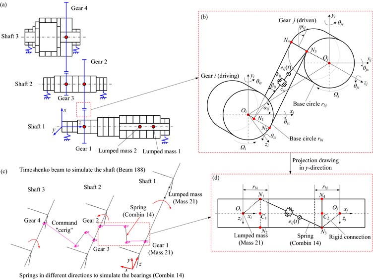
In this section, a new modeling method for geared rotor systems is developed in ANSYS software. The proposed model is verified by comparing the vibration behaviors with those obtained from Zhang’s model [22]. A brief introduction to Zhang’s model (see Figs. 1(a) and (b)) is described in Section 2.1, and the proposed model (see Figs. 1(c) and (d)) is introduced in Section 2.2.
Fig. 1a) Schematic of geared rotor systems, b) 3D model of the helical gear pair ij, c) FE model of the gear rotor system, d) projection drawing in y-direction
2.1. Dynamic models of geared rotor systems using Zhang’s method
A 3D mathematical model of helical gear pair with 12 degrees of freedom (DOFs) is displayed in Fig. 1(b), which includes two helical gears ( and ). , , , , and denote the rotational speeds, geometrical centers, radii of base circles of the gears and . The flexible of gears are ignored and assumed to be the rigid disks. In addition, a spring-damping setting is adopted to simulate the gear meshing and the direction is defined according to the helix angle . The spring stiffness is determined by the average gear mesh stiffness due to the high contact ratio of helical gear. It is worth noting that Zhang’s method in Ref. [22] takes the effects of gear geometric eccentricity into account. However, in this paper the eccentric effect is ignored. Helix angle is defined as:
As shown in Fig. 1(b), the angle between the connecting line of gear centers and the positive -axis of gear is defined as relative position angle . The angle between the plane of action and positive -axis can be defined by . Under different direction of rotation of driving gear, can be expressed as follows:
where is the lateral pressure angle of gear pairs.
The meshing position changes under the different direction of rotation of the driving gear. Considering this changing, a sgn function can be defined as follows:
The displacement vector of the gear pair can be written as follows:
Due to the equilibriums of lateral motion and force, the equations of motion of the gear pair can be written as the following expressions, where the influence of the geometric eccentricity of gear is ignored:
where and denote the masses of gear and gear . , , , , and are the moments of inertia about , and axis. denotes the averaged meshing stiffness of gear pair . represents the meshing damping of gear pair . In a direction, normal to contact surface, the relative displacement of gear mesh is written as:
where denotes the static transmission error, and it is a displacement excitation in the same direction of . The can be defined as:
where denotes the amplitude of static transmission error (STE) of the gear pair . and denote the number of tooth and rotational speed of gear .
Substituting Eqs. (6) and (7) into Eq. (5), the equations of motion of the helical gear pair are rewritten as follows:
where , , and denote the mass, damping, gyroscopic and mesh stiffness matrices of the gear pair . and are the excitation force vectors. And they can be expressed as:
where can be expressed as follows:
In Ref. [22], the shafts are simulated using Timoshenko beam elements, and some rigid disks on the shaft are simulated using lumped mass elements. By introducing the lumped mass models of gear pairs into the FE models of the shafts, equations of motions of the entire system can be expressed as:
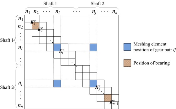
where , , , and are the mass, damping, stiffness and gyroscopic matrices. is the external force vector of the system. Here, the stiffness matrix of bearing is expressed as . According to the position of bearings and gears, the bearing stiffness matrix and mesh stiffness matrix are added to the stiffness matrix of the shafts. As shown in Fig. 2, total stiffness matrix of system is assembled, in which only two shafts are di splayed. The Rayleigh-type damping is adopted in this study, which can be expressed as:
where:
here, and denote the first-order and the second-order natural frequencies (Hz), respectively. In this paper, modal damping ratios 0.04.
2.2. A new mathematical model of gear rotor system
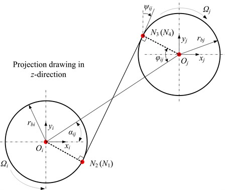
In this section, a new dynamic model is presented using FE method based on ANSYS software. Gear meshing is modeled as two lumped masses connecting by a liner spring, which is normal to the gear tooth contact surface, as shown in Figs. 1(b) and (d). According to the direction of the load, the direction of action plane changes. Here, a driving gear with counterclockwise rotation and left hand teeth is taken as a example, as shown in Figs. 1(b) and (d), in which the tangent lines and can be determined according to the geometrical relationship. The length between and can be calculated as (see Fig. 3):
Fig. 2Schematic of the whole stiffness matrix
The length of and can be expressed as:
Considering the symmetry of the gears about plane, and are divided into two equal parts i.e. , as shown in Fig. 1d. The coordinates of and can be written as (see Fig. 3):
where, , , , , , , , , , , and denote the coordinates of , , and in , and directions. Once these coordinates are determined, the direction of spring can be defined, i.e., the meshing relation of two gears can be determined. Here, for the convenience of the modeling, and are selected as the ends of spring.
There are four working modes for the driving gear , i.e., counterclockwise rotation and left-hand teeth, counterclockwise rotation and right-hand teeth, clockwise rotation and left-hand teeth, clockwise rotation and right-hand teeth. Thus the positions of spring will change under different cases. However, these coordinates of the two ends of spring for the four cases can be expressed as:
where , , , , and denote the coordinates of the two ends of spring in , and directions, respectively.
In ANSYS software, the detailed modeling process is briefly introduced as follows (see Fig. 1(c)): (1) According to the physical dimensions of the shafts and the actual gear positions, the FE models of bearing-rotor systems including bearings, shafts, gears and rigid disks are established; (2) The coordinates of gears are determined, and then the coordinates of the two ends of the meshing spring are determined based on Eq. (23); (3) Rigid connections are established between the ends of meshing springs and gears by using the command “cerig”. Thus, the FE model of the whole gear rotor system will be established.
For the gear static transmission error excitations, it is loaded on both ends of meshing spring in an opposite direction along the direction of spring. And the excitation force due to the static transmission error can be written as:
Fig. 3Projection drawing of Fig. 1(b) in z-direction
3. Model verification and discussion
In order to prove the validity of the present method, two gear rotor systems offered in Refs. [1, 9] are adopted. First of all, the present method will be verified by comparing the natural characteristics with those obtained using different methods in published literatures. Subsequently, the vibration responses obtained from present method and previous methods will be compared to verify the present method.
3.1. Model verification by comparing the natural characteristics
A spur gear rotor system is taken into account at first (see Fig. 4), and the parameters of system are listed in Table 1, which are offered in Refs. [9, 24]. Here, the effect of damping is ignored, and the helix angel is equal to zero for the spur gear. The first 11 orders of natural frequencies calculated by present method are compared with the results of Ref. [9] (see Table 2). At the same time, the descriptions of the mode shapes based on the present method are also listed in Table 2. It is obvious that the frequencies obtained by present method agree well with those offered in Ref. [9] except for some higher modes, and the relative error is less than 3.31 %.
Table 1Parameters of the gear system
Gear parameters | |||||||||
Gear | (kg·m2) | (kg·m2) | (kg) | Base circle radius (m) | Tooth number | (N/m) | |||
1 | 0.0009 | 0.0018 | 1.84 | 0.0445 | 28 | 1×10⁸ | |||
2 | 0.0009 | 0.0018 | 1.84 | 0.0445 | 28 | ||||
Bearing parameters | |||||||||
Bearing | |||||||||
All | 1×10⁹ | 1×10⁹ | |||||||
Material parameters | |||||||||
Modulus of elasticity (GPa) | Density of material (kg/m3) | Poisson’s ratio | |||||||
207.8 | 7806.0 | 0.3 | |||||||
Fig. 4Schematic of the spur gear rotor system [9]
![Schematic of the spur gear rotor system [9]](https://static-01.extrica.com/articles/17649/17649-img4.jpg)
Table 2Natural frequencies of the spur gear rotor system
Mode no. | Natural frequencies (Hz) | Relative errors | Mode description | |
Present method | Ref. [9] | |||
572.61 | 581 | 1.44 % | Coupled lateral-torsional vibration | |
678.68 | 687 | 1.21 % | 1st lateral, -direction, driving shaft | |
679.64 | 689 | 1.36 % | Coupled lateral- torsional vibration | |
680.61 | 691 | 1.50 % | 1st lateral, -direction, driven shaft | |
2513.4 | 2524 | 0.42 % | Coupled lateral-torsional vibration | |
3371.0 | 3387 | 0.47 % | 2nd lateral, -direction, driving shaft | |
3371.0 | 3387 | 0.47 % | 2nd lateral, -direction, driving shaft | |
3395.3 | 3421 | 0.75 % | 2nd lateral, -direction, driven shaft | |
3395.4 | 3421 | 0.75 % | 2nd lateral, -direction, driven shaft | |
6322.3 | 6447 | 1.93 % | Torsional, -direction, driving shaft | |
6322.3 | 6539 | 3.31 % | Torsional, -direction, driven shaft | |
In this section, a two-stage helical gear rotor system offered in Ref. [1] is taken for further comparison, as shown in Fig. 1(a). Here, the example system with 0 and 0 is considered, and the detailed parameters of the system and the STE of gear can be found in Ref. [2]. The lumped mass values and the material parameters, which are not provided in Ref. [1], can be found in Ref. [22]. The natural frequencies are calculated using Zhang’s method and present method, as listed in Table 3. In addition, the typical mode shapes obtained from two methods are shown in Fig. 5, which shows that the natural frequencies and mode shapes obtained from the present method agree well with those obtained from Zhang’s method, and the maximum relative error of natural frequency is less than 2.17 % (see Table 3).
Fig. 5Partial mode shapes: a) fn1, b) fn2, c) fn3, d) fn4, e) fn5, f) fn7, g) fn9
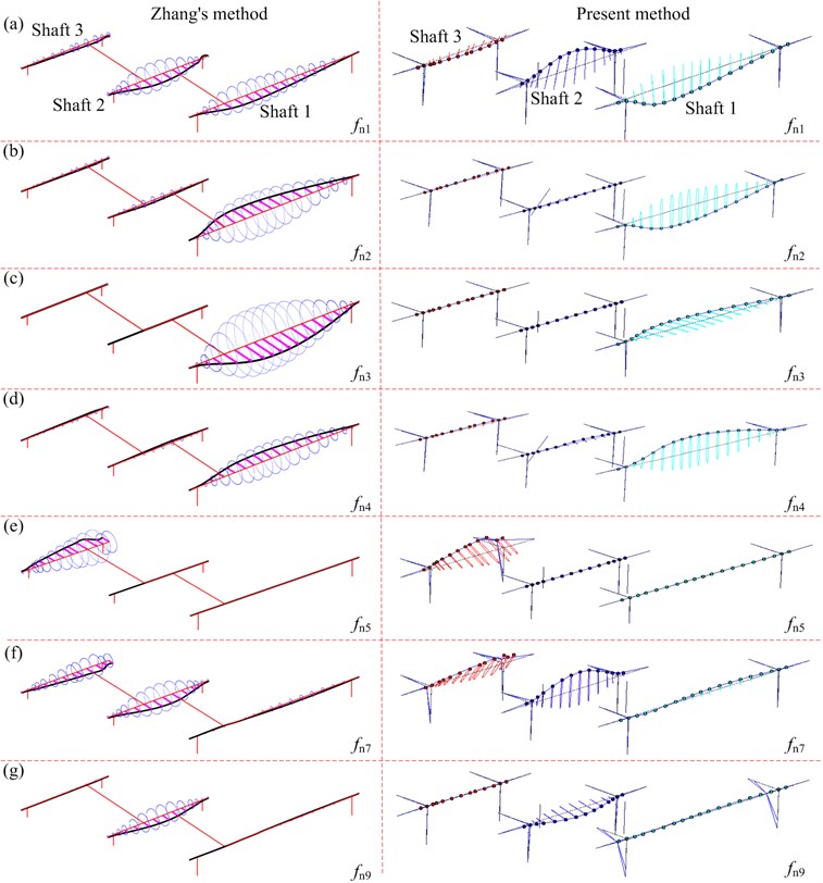
Fig. 6Mode shape corresponding to 812 Hz in Ref. [1]
![Mode shape corresponding to 812 Hz in Ref. [1]](https://static-01.extrica.com/articles/17649/17649-img6.jpg)
In Ref. [1], only a mode shape corresponding to 812 Hz is provided, as shown in Fig. 6. This mode corresponds to the first non-rigid mode in present method. It is clear that the natural frequencies and mode shapes obtained by present method also show a good agreement with those provided in Ref. [1]. These comparisons show that the present model is effective to calculate the natural characteristics of the geared rotor systems.
Table 3Natural frequencies of the helical gear rotor system
Mode No. | Natural frequencies (Hz) | Relative errors | |
Present method (Hz) | Zhang’s method (Hz) | ||
808.49 | 806.84 | –0.2 % | |
1357.05 | 1337.42 | –1.47 % | |
1468.04 | 1543.27 | –1.02 % | |
1658.66 | 1669.46 | 0.65 % | |
2334.52 | 2321.96 | –0.54 % | |
2349.00 | 2345.32 | –0.16 % | |
2368.75 | 2364.55 | –0.18 % | |
2553.83 | 2545.12 | –0.34 % | |
2656.51 | 2657.08 | 0.02 % | |
2845.74 | 2859.26 | 0.47 % | |
2988.27 | 3054.63 | 2.17 % | |
3045.66 | 3060.67 | 0.49 % | |
3287.33 | 3262.50 | –0.76 % | |
3338.58 | 3268.07 | –2.16 % | |
3749.98 | 3785.57 | 0.94 % | |
3.2. Model verification by comparing the vibration responses
In this section, the present dynamic model is further verified by comparing the vibration responses with those in Refs. [1, 2] and Zhang’s method [22]. Considering the excitation force due to the static transmission error (Eq. (24)), (meshing force of gear pair 12) and (meshing force of gear pair 34) are calculated using the present method, and they are also compared with the results in Ref. [2] (see Fig. 7). In the figure, and denote the meshing frequencies of gear pairs 12 and 34. The figure shows that two peaks ( and ) obtained from the present method agree well with those in Ref. [2], however, there are some errors for other peaks. Some reasons may lead to these errors as follows: 1) Some geometric parameters may be different because of the lack in Ref. [2], and some parameters of system are adopted by referring to the Ref. [22]. 2) The torque and other working condition are not provided in Ref. [2].
Fig. 7Dynamic meshing forces: a) gear pair 12, b) gear pair 34
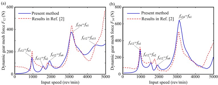
Fig. 8Gear meshing force amplitudes and maximum values under T= 50 Nm: a) meshing force amplitude of F12, b) maximum values of F12, c) meshing force amplitude of F34, d) maximum values of gear pair F34
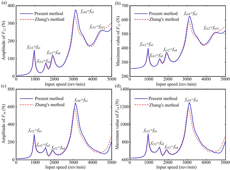
Fig. 9Vibration responses under T= 100 Nm: a) y-direction responses of gear 1; b) θz-direction responses of gear 1; c) y-direction responses of gear 2; d) θz-direction responses of gear 2
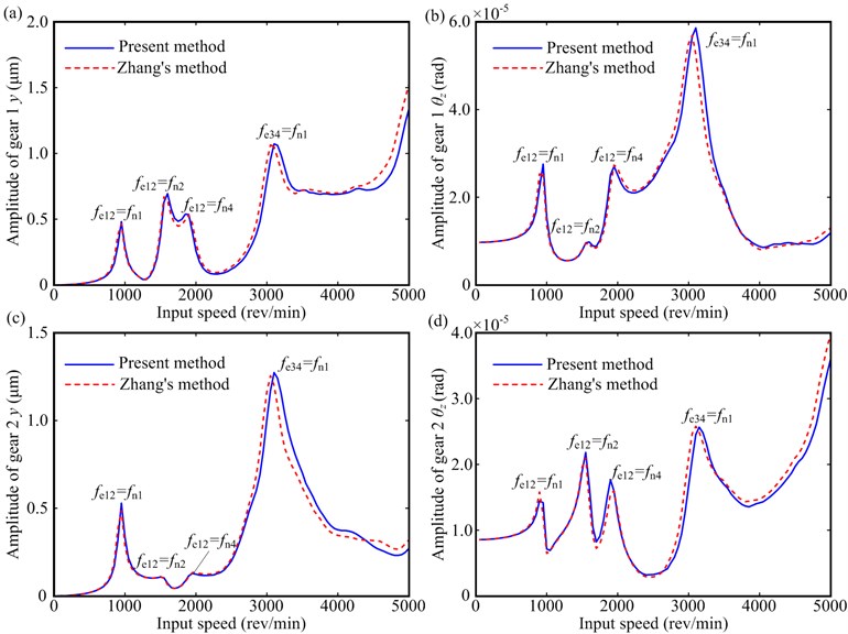
Vibration responses of the helical gear rotor system under 50 Nm and 100 Nm are shown in Figs. 8, 9 and 10, respectively. These figures show the following dynamic characteristics:
(1) Meshing forces, vibration displacements, and frequency components obtained from the present method agree well with those obtained from Zhang's method under lower frequency regions, and there exist slight errors under higher frequency regions (see Figs. 8 and 9). The main reason of the slight error may be that some high order terms due to the lateral-torsional-axial-swing coupling of gear pairs are ignored for Zhang’s method.
(2) The resonant peaks of the rotor system appear under , , , and (see Table 3), which are primary members of the lateral-torsional coupling vibration (see Fig. 5). For these modes, the vibration of shaft 1 is dominated (see Fig. 5), and the vibration mode at the first natural frequency is easily excited (see Figs. 8 and 9).
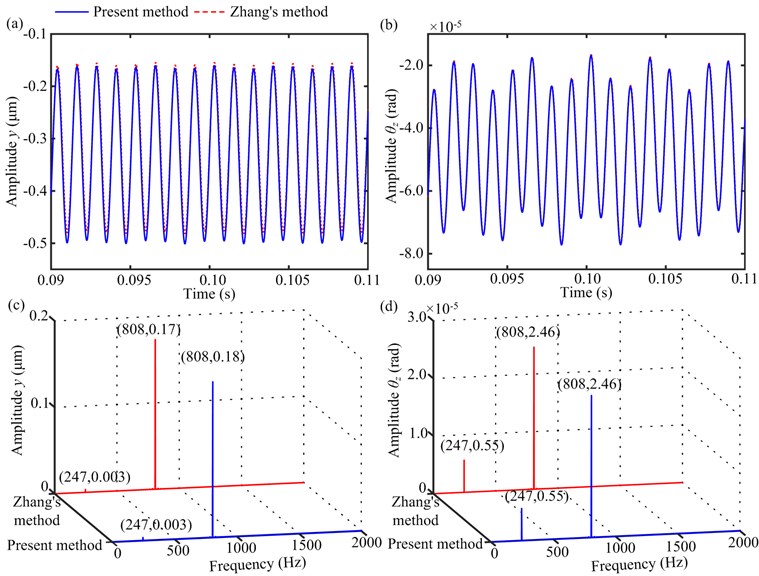
(3) The vibration responses at 932 rev/min show that two meshing frequencies of the gear pairs 12 and 34 (808 Hz and 247 Hz) can be observed (see Fig. 10). The amplitude at meshing frequency of 808 Hz is dominated because the meshing frequency coincides with . In addition, the torsional vibration is easily excited relative to the lateral vibration (see Fig. 10).
Fig. 10Vibration responses of gear 4 under T= 50 Nm and Ω1= 932 rev/min: a) time-domain waveforms in y-direction, b) time-domain waveforms in θz-direction, c) amplitude spectra in y-direction, d) amplitude spectra in θz-direction
4. Conclusions
In ANSYS software, a new finite element model for general helical gear rotor systems is presented taking the lateral-torsional-axial-swing coupling due to helical gear pairs into account. The proposed method is validated by comparing the natural characteristics and vibration responses with those obtained from the published references and Zhang’s method. Main conclusions are listed as follows:
1) The proposed method can easily deal with the meshing relation of gear pairs by conveniently calculating the displacement of the meshing spring. The new method not only has a good calculation accuracy, but also can greatly reduce the difficulty of programming relative to the conventional method, such as Kubur’s method [1, 2] and Zhang’s method [6].
2) For the studied geared rotor system provided in Ref. [2], the results show that the first-, second- and fourth-order natural frequencies are more easily excited, especially the first natural frequency. In addition, for the studied geared rotor system, the torsional vibration is easily excited relative to the lateral vibration at a low rotational speed.
References
-
Kubur M., Kahraman A., Zini D. M., et al. Dynamic analysis of multi-mesh helical gear sets by finite elements. ASME 2003 International Design Engineering Technical Conferences and Computers and Information in Engineering Conference, American Society of Mechanical Engineers, Chicago, USA, 2003, p. 333-343.
-
Kubur M., Kahraman A., Zini D. M., et al. Dynamic analysis of a multi-shaft helical gear transmission by finite elements: model and experiment. Journal of Vibration and Acoustics, Vol. 126, Issue 3, 2004, p. 398-406.
-
Ma H., Zeng J., Feng R., et al. Review on dynamics of cracked gear systems. Engineering Failure Analysis, Vol. 55, 2015, p. 224-245.
-
Iida H., Tamura A., Kikuchi K., et al. Coupled torsional-flexural vibration of a shaft in a geared system of rotors: 1st report. Bulletin of JSME, Vol. 23, Issue 186, 1980, p. 2111-2117.
-
Choy F. K., Tu Y. K., Zakrajsek J. J., et al. Effects of gear box vibration and mass imbalance on the dynamics of multistage gear transmission. Journal of Vibration and Acoustics, Vol. 113, Issue 3, 1991, p. 333-344.
-
Kahraman A., Singh R. Interactions between time-varying mesh stiffness and clearance non-linearities in a geared system. Journal of Sound and Vibration, Vol. 146, Issue 1, 1991, p. 135-156.
-
Lim T. C., Singh R. Vibration transmission through rolling element bearings. Part III: Geared rotor system studies. Journal of Sound and Vibration, Vol. 151, Issue 1, 1991, p. 31-54.
-
Özgüven H. N. A non-linear mathematical model for dynamic analysis of spur gears including shaft and bearing dynamics. Journal of Sound and Vibration, Vol. 145, Issue 2, 1991, p. 239-260.
-
Kahraman A., Ozguven H. N., Houser D. R., et al. Dynamic analysis of geared rotors by finite elements. Journal of Mechanical Design, Vol. 114, Issue 3, 1992, p. 507-514.
-
Rao J. S., Shiau T. N., Chang J. R. Theoretical analysis of lateral response due to torsional excitation of geared rotors. Mechanism and Machine Theory, Vol. 33, Issue 6, 1998, p. 761-783.
-
Jia S., Howard I., Wang J. The dynamic modeling of multiple pairs of spur gears in mesh, including friction and geometrical errors. International Journal of Rotating Machinery, Vol. 9, Issue 6, 2003, p. 437-442.
-
Lee A. S., Ha J. W., Choi D. H. Coupled lateral and torsional vibration characteristics of a speed increasing geared rotor-bearing system. Journal of Sound and Vibration, Vol. 263, Issue 4, 2003, p. 725-742.
-
Ma H., Pang X., Feng R., et al. Evaluation of optimum profile modification curves of profile shifted spur gears based on vibration responses. Mechanical Systems and Signal Processing, Vols. 70-71, 2016, p. 1131-1149.
-
Ma H., Pang X., Feng R., et al. Fault features analysis of cracked gear considering the effects of the extended tooth contact. Engineering Failure Analysis, Vol. 48, 2015, p. 105-120.
-
Ma H., Song R., Pang X., et al. Fault feature analysis of a cracked gear coupled rotor system. Mathematical Problems in Engineering, Vol. 2014, 2014, p. 1-22.
-
Ma H., Yang J., Song R., et al. Effects of tip relief on vibration responses of a geared rotor system. Proceedings of the Institution of Mechanical Engineers Part C: Journal of Mechanical Engineering Science, Vol. 228, Issue 7, 2014, p. 1132-1154.
-
Ma H., Pang X., Zeng J., et al. Effects of gear crack propagation paths on vibration responses of the perforated gear system. Mechanical Systems and Signal Processing, Vol. 62, 2015, p. 113-128.
-
Blankenship G. W., Singh R. A new gear mesh interface dynamic model to predict multi-dimensional force coupling and excitation. Mechanism and Machine Theory, Vol. 30, Issue 1, 1995, p. 43-57.
-
Velex P., Maatar M. A mathematical model for analyzing the influence of shape deviations and mounting errors on gear dynamic behavior. Journal of Sound and Vibration, Vol. 191, Issue 5, 1996, p. 629-660.
-
Choi S. H., Glienicke J., Han D. C., et al. Dynamic gear loads due to coupled lateral, torsional and axial vibrations in a helical geared system. Journal of Vibration and Acoustics, Vol. 121, Issue 2, 1999, p. 141-148.
-
Baud S., Velex P. Static and dynamic tooth loading in spur and helical geared systems-experiments and model validation. Journal of Mechanical Design, Vol. 124, Issue 2, 2002, p. 334-346.
-
Zhang Y. M., Wang Q. B., Ma H., et al. Dynamic analysis of three-dimensional helical geared rotor system with geometric eccentricity. Journal of Mechanical Science and Technology, Vol. 27, Issue 11, 2013, p. 3231-3242.
-
Zhang H., Zhai J. Y., Han Q. K., et al. Dynamics of a geared parallel-rotor system subjected to changing oil-bearing stiffness due to external loads. Finite Elements in Analysis and Design, Vol. 106, 2015, p. 32-40.
-
Choi S. T., Mau S. Y. Dynamic analysis of geared rotor-bearing systems by the transfer matrix method. Journal of Mechanical Design, Vol. 123, Issue 4, 2001, p. 562-568.
Cited by
About this article
This Project is funded by the Aeronautical Science Foundation of China (Grant No. 201404Q5001). This support is gratefully acknowledged.
