Abstract
Spindle-holder taper joint is one of the most crucial joints of high speed spindle system (HSS). Dynamic behavior of this taper joint is critical for predicting tool point frequency response function (FRF) and evaluating the cutting process stability. To identify the spindle-holder taper joint dynamic behavior precisely and rapidly, a novel identification technology is presented in this paper. Firstly, receptance coupling substructure analysis (RCSA) is improved to save the computing time without sacrificing the calculation precision. Secondly, instead of extracting the joint coefficients by complex fitting methodology, a receptance matrix is identified to represent the spindle-holder taper joint dynamic characteristics. Finally, the joint receptance matrix is used, coupling with the analytical model of arbitrary holder with varying overhang length and diameter, to predict FRF at the free end of spindle-holder assembly. The results show good agreements between predictions and experimentations. And it is validated that the presented identification technology is feasible. Comparing to the previous literatures, the proposed approach is less time-consuming and more accurate to reflect the nonlinear characteristics of spindle-holder taper joint.
1. Introduction
High speed machining technique (HSM) develops rapidly in manufacturing field. A typical application instance of HSM is the aerospace industry, where amazing increases of metal removal rates (MRR) result in cost savings. However, the occurrence of chatter due to the poor high speed spindle (HSS) dynamic behaviors limits the achievable MRR [1]. In general, as is the critical carrier of HSM, HSS consists of two substructures, namely spindle-bearing substructure and holder-clamp substructure. The two substructures are connected by the spindle-holder taper joint. Through this taper joint, spindle power and precision are transferred to the holder and tool as well. Thus, spindle-holder taper joint plays a critical role in HSS dynamic behaviors.
A primary obstacle to thoroughly study the HSS abilities is the identification of spindle-holder taper joint dynamic behaviors. In the last few years, numerous efforts have been made. Namazi et al. in [2] and John S. Agapiou et al. in [3] adopted the similar approaches to study the taper joint dynamics. Groups of translational and rotational spring-damper elements are considered to simulate the spindle-holder taper joint. Parameters of spring-damper elements, like stiffness and damping, are identified by using the optimization methodology. A distribute elastic interface layer was assumed to characterize the taper joint by Hamid Ahmadian et al. in [4] and [5]. Varying normal pressure along the interface is also taken into count in their analytical model. Dynamic parameters of the proposed elastic layer are obtained by minimizing the errors between FRFs derived through simulation and experimentation respectively. Xu et al. in [6] developed an approach to identify the spindle-holder taper joint parameters. Both axial and radial spring-damping elements are considered to simulate the joint dynamics. Parameters of elements are evaluated through the deduced expressions where the relationship between elements parameters and modal parameters are illustrated.
Besides, classical receptance coupling substructure analysis methodology (RCSA) is employed by research communities to predict the dynamic behavior of spindle-holder-tool assembly. In such a scenario, spring-damper elements are also utilized to simulate the connecting joints. Kivanc et al. in [7] proposed a comprehensive model of spindle-holder-tool assembly structure. The analytical beam model is suggested to simulate all the substructures. Spring elements are also used to represent the connection of holder and tool. Dynamics of assembly structure are evaluated through impact test while the connection elements coefficients are calculated through a fitting process. However, the rotational frequency response function (FRF) is neglected during the RCSA procedure resulting in the inaccuracy of analysis. T. Schmitz et al. in [8-14] extended the use of RCSA to predict the tool point FRF. Joints translational FRF and rotational FRF are taken into count simultaneously to form the full receptance matrix which is used for RCSA. In [15-19], E. Budak et al. also computed the joint rotational FRF. Thus the full receptance matrix is established in the RCSA to guarantee a good accuracy for predicting tool tip FRF. Nevertheless, in these works, the spindle-holder taper joint is treated as a rigid connection. A set of spring-damper elements are insert into the interface between the spindle end and holder flange to be equivalent to taper joint characteristics. And researchers use fitting to experimental data as a method to identify the stiffness and damping coefficients of spring-damper elements.
Apparently, dealing with the problem of taper joint dynamic behaviors identification, research works done before can be classified into two categories: one is to build the spring-damper elements along the taper joint interface, another is to build the spring-damper elements between the spindle end and holder flange. Both categories include the common error optimization procedure to extract the joint parameters based on the fitting methods. However, there are several limitations: Firstly, the fitting methods are very time consuming. Secondly, the initial values for parameters are quite sensitive to the iteration process, and the search range is so wide that equations are not universally successful for convergence. Finally, the spindle-holder taper joint is highly nonlinear. It is thus unreliable to characterize the taper joint dynamic behaviors by using these parameters.
In this paper, an improved RCSA methodology is presented first. It is based on the research work developed by Schmitz [8]. The joint rotational FRF is taken into count automatically in this improved methodology, while only joint translational FRF is used for RCSA. Therefore this method guarantees the accuracy of calculating and saves the computing time. Based on the improved RCSA, a technique is then proposed to identify the spindle-holder taper joint dynamic behaviors without adopting fitting methodologies presented in previous works. A receptance matrix which represents the dynamics of both taper joint and spindle is formulated. In the case study section, BT50 taper joint receptance matrix is identified by using the proposed technique. Coupling the joint receptance matrix with different analytical models of holder, the assembly FRFs at the free end are predicted and experimentally validated.
2. The receptance coupling substructure analysis and its improvement
2.1. Receptance coupling substructure analysis (RCSA)
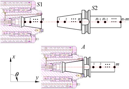
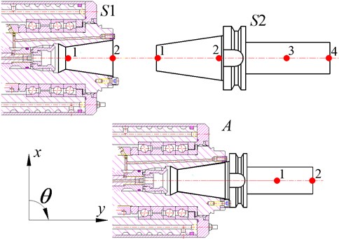
The ultimate objective of RCSA is to formulate the assembly dynamic response at any spatial coordinate by using the experimental or analytical FRFs of individual substructures. Take the spindle-holder assembly (component ) depicted in Fig. 1 as an example. Spindle substructure and holder structure are denoted as and , respectively.
As the axial degree of freedom of holder is constrained due to the clamping force, the translational displacement in direction can be neglected. However, for the holder bending inside the spindle taper hole, the rotational degree of freedom of holder must be considered. Therefore, as shown in Fig. 1, each reference point has two degrees of freedom (DOF) of and , namely the lateral displacement and the rotational angle, respectively. Thus the corresponding loads will be lateral force and moment .
As for , relationship of its receptance matrix , response vector , and corresponding load vector can be written as:
where:
Fig. 1Spindle-holder assembly and substructures
Here, is a symmetric matrix () since the substructure is assumed linear. According to the discussion above about the DOF of each reference point, for arbitrary reference points and (, 1, 2,..., ) we can write the full FRF matrix as follows:
and
where, and are the lateral displacement and rotational angle of point , respectively. and represent the lateral force and moment applied on point , respectively. Direct (, ) and cross (, ) FRF elements of the sub-matrix are defined as:
According to the reciprocity [20], can be set equal to , that is:
Similarly, for substructure and assembly , Eq. (1) will become:
where:
Also, and are symmetric. And sub-matrix (, 1, 2,..., ,..., ) and (, 1, 2,..., ) have the same expression with Eq. (5).
In order to predigest the formula expression, reference points are divided into contact points (1~) and non-contact ones (~), denoted with the lower script (contact points) and (internal points), respectively. Therefore, Eq. (1), Eq. (13) and Eq. (14) can be rewritten as:
On the basis of RCSA theories [8], the load equilibrium and displacement compatibility equations can be presented as:
Combining Eq. (21)-Eq. (25), we can get:
that is:
Substituting from Eq. (22) to Eq. (27) yields:
Therefore assembly receptance matrix in terms of the individual substructures receptance matrices is given as:
Eq. (29) is the essential equation of RCSA. It is worth emphasizing that when considering the rotational dynamics of taper joints, all the sub-matrices in Eq. (29) are described in the full form described in Eq. (5).
2.2. The improvement of RCSA
Generally, the assembly FRF obtained though RCSA is used for evaluate the limiting stable depth of cutting which is determined by the formula as follows:
where , and are constant coefficients. It is easy to see that for calculating , all we need is the real part of direct displacement/force FRF at the assembly free end, . The other three rotational FRFs (, , and ) are unnecessary to require.
However, it is now well known that the joint rotational response is significant for achieving accurate RCSA. In other words, although there is no need to calculate the rotational FRFs at the assembly free end, the rotational dynamics of joint must be considered.
Due to the experiment and instrument conditions, it is quite difficult to measure the rotational dynamics. Some researchers used translational FRF, obtained experimentally, to form the full receptance matrix for RCSA. For instance in [10], as proposed by Schmitz, making use of the experimental data, they applied a second-order backward finite difference method to estimate the rotational FRF. The works presented by Park et al. in [21] proposed an algorithm to extract the joint rotational dynamics from experimental data. Also, a new methodology to estimate the rotational dynamics is described by P. Albertelli et al. in [22]. Their methodology is deduced by taking inspiration from works reported in [10]. However, the main drawback of these proposed approaches is that experimental data is frequently contaminated by environmental noise resulting in the giant computation error.
Hence, aiming at the purpose of solving the rotational FRF issue efficiently and rapidly without sacrificing the accuracy of RCSA, an improved RCSA is proposed in this section. The improvement lies in the modeling approach of joint dynamics. Previously, to model the full dynamic response of joint, including the translational and rotational response, both translational and rotational spring elements were used as a combination. But here, instead, parallel of translational spring elements are used to characterize the full joint dynamics. While this equivalent model is applied in RCSA, relationship illustrated in Eq. (29) is maintained, but only the displacement/lateral force translational FRF, , is used.
In order to verify the equivalent model proposed above, series of numerical simulations are performed. In detail, based on analytical beam theories, three different joint models are established as depicted in Fig. 2. Each model is composed of a hollow cylinder (Beam A, representing the spindle) and a solid cylinder (Beam B, representing the holder) connected through spring elements (Spring, representing the spindle-holder taper joint) to the hollow cylinder. Model I is mostly employed in previous works. In this model, both translational and rotational spring elements at single point are suggested to simulate the joint dynamics. In model II, two points along the interface with parallel translational spring elements are used to simulate the joint dynamics. And model III only has translational spring elements at one point for joint dynamics simulation.
Fig. 2Different joint model
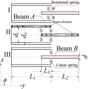
It can be verified that model I is equivalent to model II. Although no rotational spring elements are contained in model II, the joint rotational dynamic behaviors are considered automatically. On the other hand, due to the absence of rotational spring element at one point, model III may not fully reflect the same dynamic behaviors as model I. So model III may lead to the low accuracy of RCSA.
Table 1Geometry parameters of beam model
Item | Value (m) |
0.002 | |
0.005 | |
0.002 | |
0.5 | |
0.2 | |
0.1 |
By virtue of Matlab software, simulation has been carried out based on the finite element analysis (FEA). As depicted in Fig. 2, 2-node Timoshenko beam element with 2 DOFs (, ) at each node (represented by the black dots) is used to establish the beam models. Geometry parameters for the beam model are listed in Table 1. Stiffness coefficients of translational and rotational spring elements are set to equal 5×10⁵ N/m and 3×10⁴ N·m/rad, respectively. Material properties, like density, Poisson’s ratio and modulus, of the beams are 7850 kg/m3, 0.3 and 2.06×10¹¹ Pa, respectively. The corresponding eigenvalue problems then are solved to extract the first five eigenvalues (natural frequencies) and eigenvectors (mode shapes).
Mode shapes and the corresponding natural frequencies are described in Fig. 3. Table 2 resumes the errors in the estimation of natural frequencies extracted from the three models. Comparing with the results extracted from model I, calculation accuracy of model II is acceptable for the first mode, and excellent for the rest four. However on the contrary, results extracted from model III deviate from those of model I considerably. Model III simply looses the 1st mode (46 Hz), and frequency deviations of the 2nd and 4th modes are 34.02 % and 18.71 %, respectively.
It is therefore a fact that translational and rotational dynamics of joint can be fully reflected by using a parallel translational spring elements at multiple points along the joint interface (Model II). In this case, we can conclude that if the translational FRF at the free end of assembly structure is required, i.e. for predicting the cutting stability lobe diagram, one can only use the joint translational FRF for RCSA while the rotational dynamics is already considered automatically. The improved RCSA illustrated in this section is less time-consuming, where the RCSA accuracy is still guaranteed regardless the avoidance of using joint rotational FRF (, , ).
Table 2Natural frequency errors (comparing with Model I, %)
1st mode | 2nd mode | 3rd mode | 4th mode | 5th mode | |
Model II | 8.95 | 5.47 | 4.73 | 1.79 | 2.98 |
Model III | – | 34.02 | 0.99 | 18.71 | 3.33 |
Fig. 3Extracted eigenvalues and eigenvectors (solid-Beam A, dash-Beam B)
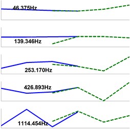
a) Model I
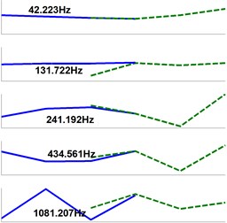
b) Model II
c) Model III
3. Identification technique of spindle-holder taper joint dynamic behavior
3.1. Definition of spindle-holder taper joint dynamic behavior
The fundamental formulation for identification of spindle-holder taper joint dynamic behaviors is Eq. (22). The goal is to identify the joint receptance matrix . The receptance matrices, i.e. , , and of the holder (substructure ) can be obtained using beam theory and FEA, since the holder is a linear structure. Receptance matrix of assembly is measured experimentally by impact testing. Assume that:
yields:
Once is provided, spindle-holder taper joint receptance matrix can be calculated directly from Eq. (32).
Again we must emphasize the idea that receptance matrix represents the dynamic behavior of taper joint and spindle itself simultaneously. The matrix here is different from that obtained from experiment performed on the spindle. In fact, the taper joint inside substructure is inaccessible to perform impact test. As long as the spindle-holder taper joint has the same conditions, i.e. geometry information and clamping force, the taper joint receptance matrix can be regarded as the constant property of spindle-holder assembly.
3.2. Dimensions of spindle-holder taper joint receptance matrix
Dimensions of depends on the number of elements required identification. According to Eq. (2) and Eq. (5), is a 2×2 matrix due to the 2 DOFs (, ) at each reference point. Considering the symmetry of and reciprocity of its sub-matrix, as Eq. (12), there are independent elements. Among these independent elements, of them are displacement/force translational FRFs, while the rest are rotational FRFs. Based on improve RCSA methodology proposed in Section 2.2, parallel translational FRFs of joint can express both its translational and rotational dynamics. Thus, the number of elements required identification in is .
On the other hand, for determining , ought to at least have the same number of independent measured elements. The number of independent measured elements in is , as we can only measure the translational FRF. For sake of simplicity, we assumed that:
Moreover, based on [23], we can prove that actually contains only 3 independent elements, while the other FRFs can obtained directly though RCSA. So has 3 independent elements in accordance with Eq. (32).
Hence, we have:
then the number of reference points, which is finally depicted in Fig. 4, is obtained:
It can be concluded that spindle-holder taper joint receptance matrix is a matrix. In addition, the improved RCSA in Section 2.2 has validated that a couple of parallel translational FRFs at 2 points along joint is sufficient for predicting the translational FRF at free end of assembly structure.
Fig. 4Reference points on spindle-holder assembly and substructures
3.3. Spindle-holder taper joint receptance matrix calculation
Consequently, Eq. (21)-(23) can be rewritten as:
Assume that , and are the three independent elements of matrix in Eq. (31):
Eq. (29) can be updated:
where:
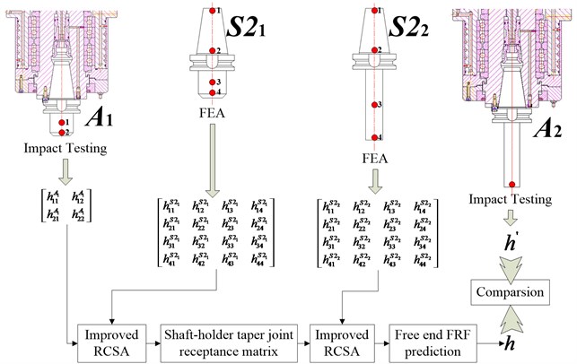
Once , and are known, Eq. (32) can be used to identify spindle-holder taper joint receptance matrix . The proposed identification technique is implemented applying the following steps which are also illustrated in Fig. 5:
1) Impact test on spindle-holder assembly .
2) FEA for holder in free configuration.
3) Identification of spindle-holder taper joint receptance matrix using improved RCSA.
4) FEA for holder in free configuration.
5) Prediction of assembly FRF at the free end (point 2) of based on improved RCSA.
6) Impact test on spindle-holder assembly to validate the prediction performed in Eq. (5).
Fig. 5Complete process for the identification and validation of taper joint dynamics
4. Numerical investigation and experimental validation
4.1. Acquisition for the receptance matrix of holder substructure
Since the Euler-Bernoulli beam theory neglects the effects of rotary inertia and shear deformation, it has been found insufficient for structure dynamic modeling [24-27]. Timoshenko beam theory is employed to model the BT 50 holder substructure (see Fig. 6(a)) in this paper. Proportional or Rayleigh is assumed for structure dynamic modeling, thus we have:
where and are the mass and stiffness damping coefficients, respectively. Both coefficients can be obtained from impact test [28]. Then based on the principle of Hamilton and FEA, general dynamic equation for holder substructure is written. See Eq. (42):
where , and are mass, damping and stiffness matrices, respectively. is the displacement vector. is the force vector.
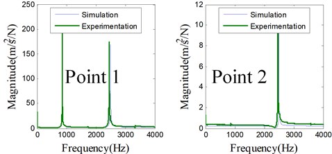
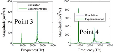
Dynamic model of holder is established. The elastic modulus and density of holder are 2.06×10¹¹ Pa and 7850 kg/m3, respectively. The model is validated experimentally through impact test. Experimentation setup is shown in Fig. 6, where single direction accelerometer is used for measuring the response. The simulated and measured direct FRF at each reference point of holder are compared in Fig. 7, where the agreements are excellent. Hence the analytical approach for dynamic modeling substructure is reliable. The matrix in Eq. (37) is then obtained numerically based on this dynamic model.
Fig. 6Impact test on holder S21 in free configuration
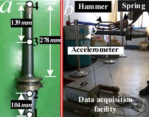
Fig. 7Comparison of each direct FRF at the reference points of holder S21
4.2. Acquisition for the receptance matrix of spindle-holder assembly
In this section, substructure is mounted on a machine tool spindle system to form the spindle-holder assembly . Impact tests are performed on the overhang as shown in Fig. 8, where point 2 is the free end of . The 2×2 matrix in Eq. (38) is then obtained experimentally.
Fig. 8Impact test on spindle-holder assembly A1
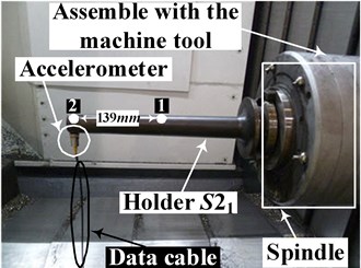
During the measuring procedure, one must be aware of the coherence of the input and output signal. Coherence simply reflects the signal quality. As depicted in Fig. 9, within the frequency range (0-2000 Hz) we concern about, most part of the coherences of estimated FRF approximate to 1. Coherence of , direct FRF at point 1, is not good close to 1120 Hz. One possible cause may be the characteristics of accelerometer [29]; another one may be the nonlinear feature of the machine tool due to the joints like bearings, ball screws, bolts and so on. But in general, the experimental data are reliable.
Fig. 9Coherences of impact test
4.3. Identification for the spindle-holder taper joint receptance matrix
Substituting the matrices obtained in Section 4.1 and 4.2 into Eq. (41) and Eq. (32), the spindle-holder taper joint receptance matrix is finally determined. In this section, two more different holders, and , are used to identify by repeating the works in Section 4.1 and 4.2. Geometry information can be found in Fig. 10 and Table 3. Three holders have different dimensions of overhang, but the same taper end geometry and clamping force. For convenience, taper joint receptance matrices obtained by using three different holders are denoted as , and , respectively.
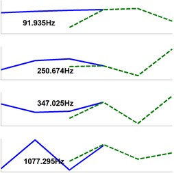
Direct (, ) and cross () FRF elements in , and are compared in Fig. 11.
Table 3Holder geometry information
Holder | Overhang taper (degree) | Radius of free end (mm) |
3 | 30 | |
5 | 63 | |
1 | 47 |
Fig. 10Three holders with different overhang dimensions
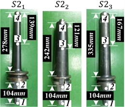
Fig. 11Elements in taper joint receptance matrix RccS1 S21, RccS1 S22 and RccS1 S23
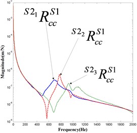
a)
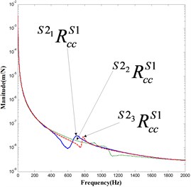
b) (or )
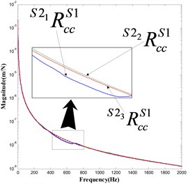
c)
Fig. 12Holder and bolt nail
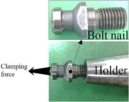
Fig. 11 shows good agreements among curves. However, differences do exist among curves, especially in a). The reason is that when experiments are carried out on assemblies (, and ) with respect to three different holders, same clamping conditions are not guaranteed strictly. As shown in Fig. 12, the holder is clamped through a bolt nail which is mounted on the holder taper end manually. Workers simply cannot assemble this bolt nail with the same torque every time, which, we believe, results in , and the different clamping conditions.
But in general, matches with each other well. This observation helps to validate the conclusion that dimensions of holder overhang have no effect on the taper joint dynamic behaviors.
5. Prediction and validation for the assembly FRF at the free end
According to Section 4.3, any holder among , , and used for identification leads to the same spindle-holder taper joint receptance matrix. Next, taper joint receptance matrix , extracted by using , is used for predicting the FRF at free end of spindle-holder assembly and . The analytically predicted and experimentally measured FRF at the free end of and assembled to spindle are compared in Fig. 13-14.
Fig. 13Comparison of FRF at the free end (point 2) of A2
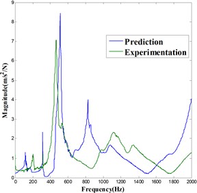
Fig. 14Comparison of FRF at the free end (point 2) of A3
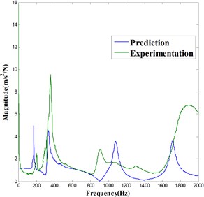
It is observed that the prediction accuracy is good for and acceptable for . However, the errors do exist between the predicting and experimental curves with respect to the frequencies and magnitudes of peaks. The possible reasons lie in two aspects as follows:
Firstly, the damping issue. There are many joints existing in the machine tool. Most of the machine tool structural damping is provided by these typical joints such as bearings, ball screws, and bolts, etc. However, the typical joints damping yet is still not studied comprehensively, which leads to the errors between prediction and experimentation. Secondly, environmental noise issue. The experiment, where the holder is assembled with machine tool, is carried out in the workshop. During the test procedure, it is inevitable that the both input and output data will be seriously contaminated by the environmental noise, resulting in the low order of the signal to noise ratio in measurements. In order to increase the prediction accuracy, filter methods must be applied to pre-process the signals in the future research works.
6. Conclusions
This paper brings a technique for identification of spindle-holder taper joint dynamic behaviors. The presented technique is based on an improvement of receptance coupling substructure analysis (RCSA) methodology, which overcomes the main obstacle for measuring or calculating rotational FRF. The improved RCSA basically deals with the absence of rotational FRF at single joint point by means of parallel translational FRF at two joint points. The computing accuracy is guaranteed, but the computing time is saved.
The great benefit of the presented identification technique is that the spindle-holder taper joint dynamic behaviors are characterized by a receptance matrix. There is no need, unlike the previous research works, to identify the joint coefficients using fitting methodologies. In addition, receptance matrix of the taper joint is only relevant to the taper geometry information and the clamping conditions. Dimensions of holder overhang have no effect on the taper joint receptance matrix, which is studied numerically and experimentally.
BT50 spindle-holder taper joint dynamic receptance matrix is extracted using the proposed identification technique. Coupling the taper joint receptance matrix with FRFs obtained from FEA model of different holders that have various overhang dimensions, FRF at the free end of spindle-holder assembly is predicted. Experimental validation shows a good agreement with the predicted FRF. The identification technique is therefore feasible and reliable. It can be developed for predicting different taper joint dynamic behaviors in the future.
References
-
Altintas Y., Weck M. Chatter stability of metal cutting and grinding CIRP. Annals – Manufacturing Technology, Vol. 53, Issue 2, 2004, p. 619-642.
-
Mehdi Namazi, Yusuf Altintas, Taro Abe, et al. Modeling and identification of tool holder-spindle interface dynamics. International Journal of Machine Tools & Manufacture, Vol. 47, 2007, p. 1333-1341.
-
John S. Agapiou A methodology to measure joint stiffness parameters for tool-holder-spindle interfaces. Journal of Manufacturing System, Vol. 24, Issue 1, 2005, p. 13-20.
-
Keivan Ahmadi, Hamid Ahmadian Modeling machine tool dynamics using a distributed parameter tool-holder joint interface. International Journal of Machine Tools & Manufacture, Vol. 47, 2007, p. 1916-1928.
-
Hamid Ahmadian, Mostafa Nourmohammadi Tool point dynamics prediction by a three-component model utilizing distributed joint interfaces. International Journal of Machine Tools & Manufacture, Vol. 50, 2010, p. 998-1005.
-
Albertelli P., Goletti M., Monno M. Dynamic modeling and parameters identification of a spindle-holder taper joint. International Journal of Advanced Manufacturing Technology, Vol. 67, 2013, p. 1517-1525.
-
Kivanc E. B., Budak E. Structural modeling of end mills for form error and stability analysis. International Journal of Machine Tools & Manufacture, Vol. 44, 2004, p. 1151-1161.
-
Tony L. Schmitz, Matthew A. Davies, Michael D. Kennedy Tool point frequency response prediction for high-speed machining by RCSA. Journal of Manufacturing Science and Engineering, Vol. 123, 2001, p. 700-707.
-
Tony L. Schmitz, Kevin Powell, Dongki Won, et al. Shrink fit tool holder connection stiffness/damping modeling for frequency response prediction in milling. International Journal of Machine Tools & Manufacture, Vol. 47, 2007, p. 1368-1380.
-
Tony L. Schmitz, Scott G. Duncan Three-component receptance coupling substructure analysis for tool point dynamics prediction. Journal of Manufacturing Science and Engineering, Vol. 127, 2005, p. 781-790.
-
Tony L. Schmitz, G. Scott Duncan Receptance coupling for dynamics prediction of assemblies with coincident neutral axes. Journal of Sound and Vibration, Vol. 289, 2006, p. 1045-1065.
-
Filiz S., Cheng C. H., Powell K. B., Schmitz T. L., et al. An improved tool-holder model for RCSA tool-point frequency response prediction. Precision Engineering, Vol. 33, 2009, p. 26-36.
-
Jun Zhang, Tony L. Schmitz, Wanhua Zhao, Bingheng Lu Receptance coupling for tool point dynamics prediction on machine tools. Chinese Journal of Mechanical Engineering, Vol. 24, 2011, p. 340-345.
-
Uttara V. Kumar, Tony L. Schmitz Spindle dynamics identification for receptance coupling substructure analysis. Precision Engineering, Vol. 36, 2012, p. 435-443.
-
Erturk A., Ozguven H. N., Budak E. Analytical modeling of spindle-tool dynamics on machine tools using Timoshenko beam model and receptance coupling for the prediction of tool point FRF. International Journal of Machine Tools & Manufacture, Vol. 46, 2006, p. 1901-1912.
-
Erturk A., Ozguven H. N., Budak E. Effect analysis of bearing and interface dynamics on tool point FRF for chatter stability in machine tools by using a new analytical model for spindle-tool assemblies. International Journal of Machine Tools & Manufacture, Vol. 47, 2007, p. 23-32.
-
Erturk A., Budak E., Ozguven H. N. Selection of design and operational parameters in spindle-holder-tool assemblies for maximum chatter stability by using a new analytical model. International Journal of Machine Tools & Manufacture, Vol. 47, 2007, p. 1401-1409.
-
Ozsahin O., Erturk A., Ozguven H. N., et al. A closed-form approach for identification of dynamical contact parameters in spindle-holder-tool assemblies. International Journal of Machine Tools & Manufacture, Vol. 49, 2009, p. 25-35.
-
Ozsahin O., Ozguven H. N., Budak E. Analysis and compensation of mass loading effect of accelerometers on tool point FRF measurements for chatter stability predictions. International Journal of Machine Tools & Manufacture, Vol. 50, 2010, p. 585-589.
-
Ewins D. J. Modal Testing, Theory, Practice, and Application. Research Studies Press, Baldock, 2000.
-
Simon S. Park, Yusuf Altintas, Mohammad Movahhedy Receptance coupling for end mills. International Journal of Machine Tools & Manufacture, Vol. 43, 2003, p. 889-896.
-
Albertelli P., Goletti M., Monno M. A new receptance coupling substructure analysis methodology to improve chatter free cutting donditions predition. International Journal of Machine Tools & Manufacture, Vol. 72, 2013, p. 16-24.
-
Mohammad Mahdi Rezaei, Mohammad R. Movahhedy, Hamed Moradi, et al. Extending the inverse receptance coupling method for prediction of tool-holder joint dynamics in milling. Journal of Manufacturing Processes, Vol. 14, 2012, p. 199-207.
-
Ginsberg J. H. Mechanical and Structural Vibrations Theory and Applications. John Wiley & Sons, New York, 2001.
-
Filiz S., Cheng C. H., Powell K. B., et al. An improved tool–holder model for RCSA tool-point frequency response prediction. Precision Engineering, Vol. 33, 2009, p. 26-36.
-
Schmitz T., Donaldson R. Predicting high-speed machining dynamics by substructure analysis. The International Academy for Production Engineering, Vol. 49, Issue 1, 2000, p. 303-308.
-
Schmitz T., Davies M., Medicus K., Synder J. Improving high-speed machining material removal rates by rapid dynamic analysis. The International Academy for Production Engineering, Vol. 50, 2001, p. 263-268.
-
Hongqi Li, Yung C. Shin Integrated dynamic thermo-mechanic modeling of high speed spindles – part 1 – model development. Journal of Manufacturing Science and Engineering, Vol. 126, 2004, p. 148-158.
-
Ward Heylen, Stefan Lammens, Paul Sas Modal Analysis Theory and Testing. Catholic University of Leuven, Faculty of Engineering, Department of Mechanical Engineering, Division of Production Engineering, Machine Design and Automation, Leuven, 1997.
About this article

