Abstract
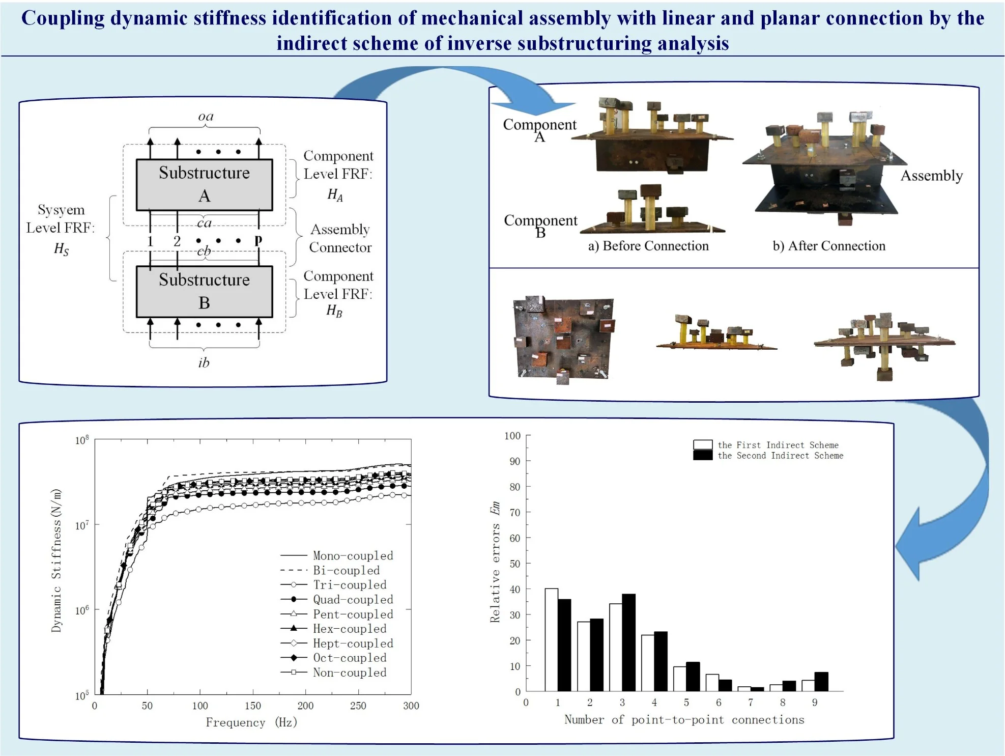
Mechanical assembly is an important process in manufacturing electromechanical products and it directly affects the dynamic quality of a whole product. The traditional inspection and analysis of mechanical assembly quality mainly focuses on the “static quality”, such as the shape accuracy and dimensional coordination, while ignoring its “dynamic quality”, which is incomplete estimation on the assembly quality. Meanwhile, the assembly coupling dynamic stiffness is a key determinant of the dynamic quality of mechanical assembly. To overcome test operation difficulties in practical application which is caused by the direct scheme of inverse substructuring of the mechanical assembly coupling dynamic stiffness, it needs to discrete the non-ideal mechanical assembly connection interface including linear and planar connection interface so as to apply two kinds of indirect method of inverse substructuring analysis based on frequency response function (FRF) spectrum to recognize its coupling dynamic stiffness. The experimental models of mechanical assembly for the more practical linear and planar connections are designed, and the practicability of applying these two methods to recognize the dynamic stiffness after assembly coupled is verified.
Highlights
- The indirect scheme of inverse substructuring analysis overcomes the difficulty of test operation in application.
- The experimental models of mechanical assembly for the linear and planar connections are designed.
- The best equivalent discrete points in the experimental model designed in this paper are determined.
1. Introduction
Complicated mechatronic products are normally combined by assembling a series of units or members according to devise requirements. Therefore, the quality inspection of mechanical assembly is an indispensable quality assurance link in the manufacture of complex electro-mechanical products. However, the normal quality inspection of mechanical assembly mainly focuses on the ‘static quality’ indicators such as tolerance and dimensional coordination [1, 2]. Usually, the dynamic quality of products, such as vibration, noise and stability, is also an important factor that cannot be ignored. In the mechanical assembly inspection, it needs to pay attention not only to the inspection system of static quality, but also to the inspection system of dynamic quality.
The dynamic performance of assembly interface or its coupling connection structure (piece) play a key part in the dynamic quality of mechanical assembly. The identification of dynamic performance or dynamic stiffness of mechanical structural joint components based on frequency response function (FRF) have been widely concerned, and there are some reports about it. For example, Majid [3] regarded the model as a point-mass connection model by adopting inverse admittance coupling, and recognized the dynamic performance of the connection by merging the experimental test with the finite element numerical simulation. In view of the difficulties in modeling the dynamic feature of structural joints by abstract and pure theory analysis, Damjan and Miha [4] have established the dynamic compliance of the beam structure by bolt connection. Hwang [5] applied FRF to model and study the structural connection parameter identification and the low identification accuracy result caused by the modal high-sensitivity area is eliminated, thereby overcoming the defect of ‘mass-damping-stiffness’ matrix model in the previous modal analysis. In a word, these theories are essentially dynamic substructure analysis methods that solve problems from the front. These methods both need to predetermine the boundary conditions of the model and some dynamic parameters of the model in advance. Therefore, the related algorithms are complex and computationally intensive. As a result, the accuracy and efficiency in practical applications need to be improved.
In light of that, Lim proposed an inverse substructure analysis method based on FRF [6], and it was applied to the vibration response analysis of automotive dynamic systems [7]. This method that use the measured system-level FRF “reverse seeking” substructure and its interface coupling dynamics appertains to the inverse analysis of structural dynamic, thus avoiding complex modal test calculations and statistical techniques, without predicting the corresponding constraint boundary conditions of the model. This method has a simple process and good effect in practical engineering applications, which has aroused widespread interest in the academic community. It is first applied to the dynamic analysis of the transportation packaging system and the dynamic stiffness calculation of the package coupling by Guang-qing Lu [8], and then Wang and Zhang [9] applied this method in the dynamic analysis design of the transportation packaging system. Mo C. and Chen J. Q. [10] studied the application of the inverse substructure analysis method in the transmission path analysis of mechanical structural systems, and improved the accuracy of the original ‘OPAX’ method. Wang Q. L. [11] designed the corresponding virtual mass method for the problem that the frequency response data of the coupling interface is difficult to detect in the actual operation of the inverse substructure method, which reduces the difficulty of the coupling interface test in the two-stage rigid coupling system to some extent. In the field of mechanical engineering, Guang-qing Lu adopted inverse substructure analysis on the mechanical assembly system, including employing the assembly coupling dynamic stiffness and the assembly coupling matrix eigenvalue [12] as the quantitative indicators to evaluate the dynamic quality of mechanical assembly.
Nowadays, the inverse substructure analysis method is generally a “direct inverse substructure” (referred to as “direct method”). It is difficult to apply the direct method to some mechanical assembly parts because the FRFs at the coupling interface required for this method are not convenient to test, so this method still needs further optimization. In order to expand the application of inverse substructure analysis method in the identification of mechanical assembly coupling dynamic stiffness, Guang-qing Lu [13] proposed five kinds of “indirect inverse substructure analysis methods” (referred to as “indirect method”) established for mechanical assembly coupling dynamic stiffness identification. And their theoretical completeness is tested by the analysis of model simulation calculations. And the feasibility and effectiveness of application for the first type of indirect method are applied to the mechanical assembly second-level sub-joint with “single-point and multi-point” interface. The experimental model of the structure was experimentally verified.
The purpose of this paper is to further improve the inverse substructure analysis method in the practical application of mechanical engineering. According to the equilibrium relationship of FRF before and after interfacial coupling in the dynamic substructure analysis theory, the “indirect” inverse substructure of the mechanical assembly coupling structure is identified. On the basis of the reference [14], the feasibility of the theory and its application are verified and analyzed systematically according to the more general practical engineering application, including (1) The secondary substructure experimental model of mechanical mounting via linear interface and (2) The secondary substructure experimental model of machine assembly with planar coupling. According to the different types of assembly coupling in actual engineering, it is divided into point connection, linear connection and planar connection, and the mechanical assembly experimental model of linear and surface coupling in the common coupling type of more practical coupling interface is designed respectively. And then the feasibility of this method in identification of coupling dynamic stiffness of linear connection mounting is tested experimentally by discretizing the interface. The interface is experimentally tested to evaluate the application practicability of the method in recognizing the coupling dynamic stiffness of linear connection mounting, and to provide a fundamental for its practical mechanical application. This paper intends to study that the indirect method is effective in more general mechanical assembly engineering, and the indirect method is simpler and more effective compared with the existing direct method. At the same time, the best equivalent discrete points in the mechanical assembly experimental model designed in this paper are determined, which is important for the test stage of mechanical assembly process.
2. The indirect schemes of inverse substructuring analysis to recognize the coupling dynamic stiffness
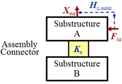
It can be found in Fig. 1 that the model of secondary substructures with ‘substructure/component A-coupling connection-substructure/component B’ can be used to equivalently describe a mechanical mounting system with discrete couplings, and denote the discrete couplings; the dynamic displacement response of output on component A and the applied dynamic force of external input on component B are expressed as and respectively; The FRF from the excitation input to the response output on the assembly coupling system is represented by that indicated the ‘FRF at system level’; the FRF from the excitation input to the response output on component A and B in the uncoupled state of the experimental model are represented by and that called the ‘FRF at component level’ of A and B, respectively; denote the coupling dynamic stiffness of the model. Particularly, matrix terms are used to represent all these parameters on the whole.
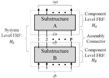
Fig. 1. The secondary substructure model with discrete coupling
According to the theory of substructure dynamic analysis, the FRF matrix before and after assembly has the following relationship [7]:
where “–1” denotes a matrix inversion; the matrix form of coupling dynamic stiffness is represented by . According to the equivalent relationship of independent matrix in Eq. (1), if the force of external input (, ) and dynamic displacement response of output (, ) are selected to be the same numbers as the discrete couplings (, ), the five indirect methods for coupling dynamic stiffness of assembly can be derived [14]. In which, the calculation formula of first and second indirect schemes are deducted.
The first indirect scheme:
The second indirect scheme:
in which, . As shown in Eqs. (1) and (2), the two kind of indirect methods completely overcome the difficulty of test operation at coupling interface after assembly. Its theoretical completeness has been tested in [13]. When Eq. (3) and Eq. (4) are used to identify stiffness, five and six FRFs are required, respectively. Using the first scheme to calculate the coupling dynamic stiffness of mechanical assembly, five FRFs need to be measured, including four FRFs at component level in the uncoupled state, , , and , and one FRF at system level after assembly, . Using the second scheme to calculate the coupling dynamic stiffness of mechanical assembly, six FRFs need to be measured, including five FRFs at component level, , , , and , and one FRF at system level, . Fig. 2 contains all the FRFs that need to be tested.
Fig. 2All the FRFS that need to be tested for the two indirect schemes
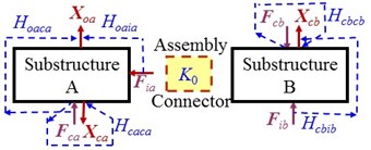
a) FRF at component level for the indirect schemes
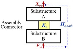
b) FRF at system level for the first indirect scheme
c) FRF at system level for the second indirect scheme
3. Experimental models of mechanical assembly with linear and planar connection
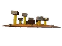
As shown in Fig. 3 and Fig. 4, the experimental models of the secondary substructure with the connection of non-idea interface is designed to verify the application feasibility of the application of the first and second indirect methods to identify the coupling dynamic stiffness, , of non-idea mechanical assembly connections. It can be seen from Fig. 3 that the component A of the experimental model of the mechanical mounting with linear connection is composed of two steel plates and bolted together (size of A1: 500×600×7 mm3; size of A2: 200×600×30 mm3), and component B is a piece of steel plate with size of 300×260×10 mm3. They have different mass of blocks are attached onto the steel plate by cylindrical damping rubber bar (Φ35 mm). The assembly interface of linear connection, a long strip damping rubber layer (30×600×10 mm3), is used to assemble the component A and B by fastening a side thickness of plate to the centerline of component B.
Fig. 3Experimental model of mechanical assembly with linear connection
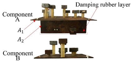
a) Before connection
b) After connection
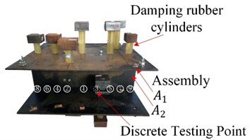
It can be seen from Fig. 4(a)-(d) that the experimental model of the mechanical mounting with planar connection is composed of two steel plates A and B bolted together (A: 500×600×5 mm3, B: 500×600×7 mm3). They also have different mass of blocks are attached onto the steel plate by cylindrical damping rubber bar (Φ35 mm). They are assembled together by the planar coupling interface which is a plain hard rubber layer (3 mm thick), as shown in Fig. 4(d). It can be seen from Fig. 4(e) that the exact positions of the mass blocks (No. 1-9) and the discretized coupling points (No. 1-9).
Fig. 4Experimental model of mechanical assembly with planar connection and its test point distribution
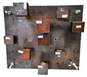
a) Component A
b) Component B
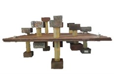
c) Assembling system
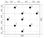
d) Discrete points
Fig. 5Test point distribution for point-to-point connections in nine cases of the model with linear coupling
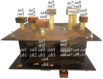
The FRF matrix elements used in the two indirect methods expressed in Eqs. (3)-(4) are based on the point-shaped connection and obtained by the test of “point-vibro-excitation to point-displacement-response” on the experimental model with linear connection.
Accordingly, it is necessary to discretize the coupling interface of linear connection as shown in Fig. 5, and make it approximately equivalent with ‘point-point connection’. The coupling interface of the model is divided into two, three, four, five, six, seven, eight, nine and ten connection segments respectively, corresponding to the formation of mono-, bi-, tri-, quad-, pent-, hex-, hept-, oct- and non-coupled equivalent discrete “point-point connection” assembly coupling interfaces. All the needed FRFs of Eqs. (3)-(4) in the nine cases of model with “point-coupling connection” in free state are obtained respectively by vibro-excitation test. The distribution of measured points of the corresponding excitation and displacement response is shown in Fig. 5. The test frequency range is 0-300 Hz.
It is equally necessary to discretize the coupling interface of planar connection as shown in Fig. 4, and make it approximately equivalent with ‘point-point connection’. The coupling interface of the model is divided into two, three, four, five, six, seven, eight, nine and ten connection segments respectively, corresponding to the formation of mono-, bi-, tri-, quad-, pent-, hex-, hept-, oct- and non-coupled equivalent discrete “point-point connection” assembly coupling interfaces. All the needed FRFs of Eqs. (3)-(4) in the nine cases of model with “point-coupling connection” in free state are obtained respectively by vibro-excitation test. The distribution of measured points of the corresponding excitation and displacement response is shown in Fig. 4(d). The test frequency range is 0-300 Hz in this study.
4. Experimental results
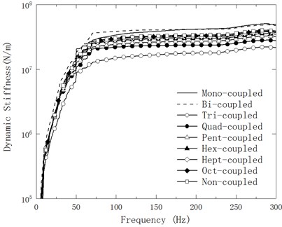
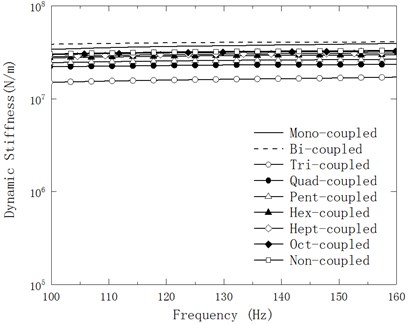
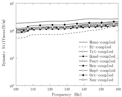
In order to obtain the assembly coupling dynamic stiffness matrix of the two experimental models that is computed by the two indirect schemes respectively, this paper measured all the entries of the 9 FRF-matrices involved in Eq. (3) and Eq. (4) respectively in the above nine cases of “point-to-point connections” on the two mechanical assembly experimental models. The average modulus value, , of diagonal entries of the matrix, (1, 2,…, , and 2-9 is the number of discrete points) is taken as the spectrum curve as shown in Fig. 6 and Fig. 7. And their amplified graphs in range of 10s0-160 Hz as shown in Fig. 7 and Fig. 8.
Fig. 6Variation of mean Ksf of the experimental model of mechanical mounting with linear connection with respect to testing frequency in nine cases of discrete points
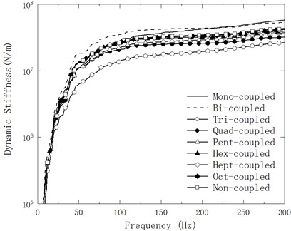
a) First indirect scheme
b) Second indirect scheme
This paper takes the mean in case of non-coupled connection denoted by as a reference to show the differences of the recognized dynamic stiffness. Within testing frequency range (0-300 Hz) of this study, the relative errors, , (1, 2,…, 9) of the nine cases are calculated by:
in which 300 is the number of discrete frequencies. List the calculated relative error, , of the two kind of experimental models of mechanical mounting in Table 1, Table 2 and Fig. 10, respectively.
Table 1The relative errors Em(%) between average Ksf and Kmf in nine cases of linear coupling
Indirect Scheme | Number of discrete points | ||||||||
Mono-coupled | Bi-coupled | Tri-coupled | Quad-coupled | Pent-coupled | Hexa-coupled | Hepta-coupled | Oct-coupled | Non-coupled | |
First | 40.09 | 27.12 | 34.11 | 22.01 | 9.62 | 6.63 | 1.85 | 2.62 | 4.27 |
Second | 35.94 | 28.29 | 37.84 | 23.22 | 11.39 | 4.43 | 1.57 | 4.04 | 7.43 |
Table 2The relative errors Em (%) between average Ksf and Kmf in nine cases of planar coupling
Indirect Scheme | Number of discrete points | ||||||||
Mono-coupled | Bi-coupled | Tri-coupled | Quad-coupled | Pent-coupled | Hexa-coupled | Hepta-coupled | Oct-coupled | Non-coupled | |
First | 13.38 | 20.33 | 12.71 | 10.46 | 5.59 | 6.98 | 6.91 | 6.94 | 6.10 |
Second | 28.90 | 14.79 | 10.40 | 13.88 | 1.89 | 6.46 | 3.00 | 10.97 | 7.62 |
It can be seen from Figs. 6-7, Fig. 10 and Tables 1-2:
1) As shown in Fig. 6(a)-(b), the coupling stiffness in the nine cases of the experimental model of mechanical assembly with linear connection obtained by the two indirect methods are on the same order of magnitude, which is about 107 N/m. This testifies that discretizing the linear connection of the coupling interface into “point-to-point connections” equivalently and applying the first and second indirect scheme to identify the stiffness of mechanical assembly are both feasible in practice.
2) The coupling dynamic stiffness of the experimental model in nine discretizing cases of planar coupling calculated by using two different indirect methods are all on the order of around 106 N/m as shown in Fig. 7(a)-(b). Therefore, it can be concluded that it is feasible to discretize the mechanical assembly coupling interface of the planar connection into ‘point-to-point connections’ by the first and second indirect methods.
3) It can be seen from Figs. 8-9 that whatever it is linear or planar connection the magnitude of the coupled dynamic stiffness is gradually closer and close to their average with the increase of discrete points. Therefore, it shows that the dynamic stiffness curves calculated by the two indirect methods tend to be stable with the increase of discrete points.
4) The results of Table 1 and Fig. 6 comprehensive show that, the coupling dynamic stiffness identified by the two indirect methods is the closest to the average of the nine discretization results obtained by each for the experimental model in this study when the linear coupling assembly coupling interface is equivalently discretized into seven ‘point-to-point connections’, and the second indirect method is closer to the first indirect method (1.57 %).
Fig. 7Variation of mean Ksf of the experimental model of mechanical mounting with planar connection with respect to testing frequency in nine cases of discrete points
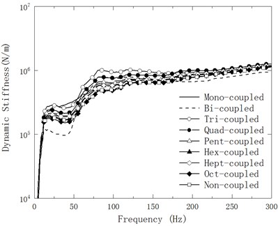
a) First indirect scheme
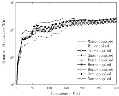
b) Second indirect scheme
Fig. 8Variation of amplified mean Ksf of the experimental model of mechanical mounting with linear connection with respect to testing frequency within 100-160 Hz in nine cases of discrete points
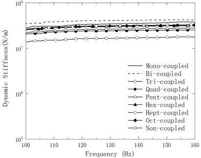
a) First indirect scheme
b) Second indirect scheme
Fig. 9Variation of amplified mean Ksf of the experimental model of mechanical mounting with planar connection with respect to testing frequency within 100-160 Hz in nine cases of discrete points
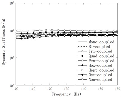
a) First indirect scheme
b) Second indirect scheme
Fig. 10Relative errors Em(%) of mean Ksf in nine cases to Kmf in case of linear and planar connection
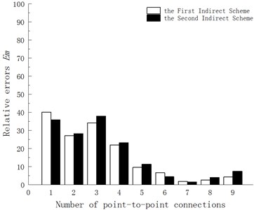
a) Linear connection
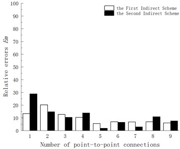
b) Planar connection
5) A comprehensive results of Table 2 and Fig. 8 can be obtained, the coupling dynamic stiffness identified by the two indirect methods is the closest to the average of the nine discretization results obtained by each for the experimental model in this study when the planar coupling assembly coupling interface is equivalently discretized into five ‘point-to-point connections’, and the second indirect method is closer to the first indirect method (1.89 %).
5. Conclusions
On purpose to apply the two indirect schemes of inverse substructuring analysis to the coupled dynamic stiffness identification of mechanical assembly of more practical linear and surface coupling interfaces, this paper is design the laboratorial model of mechanical mounting for linear and surface connection respectively. The equivalent ‘point-to-point connections’ discretization is implemented by the coupling interface. And then, the coupling dynamic stiffness of model is calculated by the scheme using the FRF-matrices tested obtained from vibration excitation experiment. The feasibility of the two indirect schemes applied to the mechanical assembly coupling dynamic stiffness identification of linear and surface coupling interfaces is verified by the experiments. The experimental results also show that there are optimal discretization points for both models. As the results of experimental study on the model with linear connection designed in this paper, a relatively stable assembly coupling dynamic stiffness can be obtained by coupling the seven discrete points. In the meantime for the results of study on experimental model with planar connection in this study, it is relatively good that the assembly coupling dynamic stiffness obtained by the coupling of five discrete points. The mechanical assembly coupling experimental model of two different connection interfaces calculated by the second indirect scheme has a more stable assembly coupling dynamic stiffness than the first indirect scheme, and the identification error is smaller.
References
-
Implementation Manual of the Procedures and Specifications of Modern Machining and the National Assessment Standards of Mechanical Assembly Quality Inspection. China Machinery Industry Press, Beijing, 2011, (in Chinese).
-
Wang Bo, Tang Xiaoqing Decision-making of quality control for mechanical assembly activities. China Mechanical Engineering, Vol. 21, Issue 2, 2010, p. 164-168+174, (in Chinese).
-
Majid M., Graham E., Park S. S. FRF based joint dynamics modeling and identification. Mechanical Systems and Signal Processing, Vol. 39, Issues 1-2, 2013, p. 265-279.
-
Damjan C., Miha B. Identification of the dynamic properties of joints using frequency response functions. Journal of Sound and Vibration, Vol. 317, Issues 1-2, 2008, p. 158-174.
-
Hwang H. Y. Identification techniques of structure connection parameter using frequency response functions. Journal of Sound and Vibration, Vol. 212, Issue 3, 1998, p. 469-479.
-
Teik Lim C., et al. An improved numerical procedure for the coupling of dynamic components using frequency response functions. Proceedings of the 9th International Modal Analysis Conference, Florence, Italy, 1991, p. 902-908.
-
Zhen J. T., Lim T. C., Lu G. Q. Determination of system vibratory response characteristics applying a spectral-based sub-structuring approach, part I: analytical formulation. International Journal of Vehicle Noise and Vibration, Vol. 1, Issues 1-2, 2004, p. 1-30.
-
Lu Guang-Qing Inverse sub-structuring analysis of dynamic stiffness of discretized coupling unit-of-packaging. Noise and Vibration Control, Vol. 29, Issue 2, 2009, p. 16-18, (in Chinese).
-
Wang Z. W., Wang J., Zhang Y. B., et al. Application of the inverse substructure method in the investigation of dynamic characteristics of product transport system. Packaging Technology and Science, Vol. 25, Issue 6, 2012, p. 351-362.
-
Mo C., Chen J. Q., Lan F. C. Improvement of operational-X transfer path analysis method. Journal of Vibration and Shock, Vol. 8, 2015, p. 129-133, (in Chinese).
-
Wang Q. L., Wang J., Sun Z. Z., et al. Inverse sub-structuring theory of rigid coupling system with incomplete measured data. Journal of Vibration Engineering, Vol. 29, Issue 4, 2016, p. 603-608, (in Chinese).
-
Lu G. Q., Fang K., Pang D. M. Eigenvalue analysis and estimation on dynamic quality of mechanical assembly. Journal of Vibroengineering, Vol. 17, Issue 8, 2015, p. 4390-4403.
-
Lu G. Q., Yi C. J., Fang K. Analysis and inverse substructuring computation on dynamic quality of mechanical assembly. Chinese Journal of Mechanical Engineering, Vol. 52, Issue 9, 2016, p. 86-95, (in Chinese).
-
Lu G. Q., Wang M. Q., Wang B., et al. Indirect inverse substructuring identification method for coupling Dynamic stiffness of vibrational structures. Acta Acustica, Vol. 43, Issue 3, 2018, p. 372-380.
About this article

The authors acknowledge gratefully the Provincial-ministerial University-industry Cooperation Project (Grant No. 2013B090600142) is supported by Guangdong Provincial Department of Science and Technology and the Project (Grant No. 51475211) is supported by National Natural Science Foundation of China.
