Abstract
Force and thermal effect are dominant in giving rise to variation of bearing dynamic stiffness and vibration. On the basis of test and theoretical analysis, the dynamic stiffness and vibration model of angle contact ball bearing considering vibration and friction state variation is established. Firstly, based on the quasi-statics of bearing and hydrodynamic lubrication theory, the motion and force relation between each parts are determined by considering the force and thermal effect. Secondly, the friction power consumption of bearing is calculated adopting integrated method, besides, the conduction heat resistance and convection heat resistance in the bearing system are achieved. A steady-state temperature calculation model of angle contact ball bearing-shaft-house system is built based on thermal network method. Finally, the dynamic stiffness and vibration model of angular contact ball bearing including the thermal-solid coupling effect is obtained, which is employed to realize the theoretical analysis of bearing dynamic stiffness and vibration, its accuracy is verified through typical test results. The calculation results shows that there is a good agreement between house test temperature and calculation temperature. The evolution rule of contact deformation and contact stiffness between ball and outer/inner ring over the whole life under excessive preload is the same. So does the oil film thickness and oil film stiffness. However, the curve shape and amplitude of contact angular between ball and outer/inner ring over the whole life is different. Bearing radial stiffness value has a more significant change than axial stiffness value, both of them represent an overall upward tendency. The radial clearance holds a negative correlation with house temperature, however, the radial displacement has a positive correlation with house temperature. The evolvement curve of contact angular affected by various preload and speed is opposite. The contact load between ball and outer/inner ring has the same trend influenced by preload and speed with EHL. The variation of preload has bigger effect on temperature rise than speed change. The oil film has little influence on contact angular, contact load and temperature under dry-lubricated or lightly lubricated condition.
Highlights
- The factors affecting the abnormal heating-up in the process of bearing service is illustrated, the angular contact ball bearing dynamic stiffness and vibration model is built
- "Thermal contribution factor" is presented, which is used to describe friction location and severity of parts during the process of bearing performance degeneration
- The bearing performance degradation simulation test rig and test system is comprised, the theoretical calculation results is verified by house temperature data recorded during the whole life of bearing under typical service condition
1. Introduction
Dynamic stiffness of angular contact ball bearing is the contact characteristic between ball and outer and inner ring raceway during bearing is running, that is, it is a transient value. In particular, the dynamic stiffness is consist of contact stiffness and oil film stiffness between ball and raceway for bearing with high speed [1, 2]. However, its dynamic stiffness tends to be changeable affected by force and thermal effect, which would have the vibration of bearing-rotor system increase and even induce rub-impact between blade and shell. Therefore, it has notable significance to guide bearing design, machining, service and maintenance by means of performing research on bearing dynamic stiffness and vibration characteristic and clarifying the mechanism of force and heat effect acting on bearing dynamic stiffness and vibration.
Early research on bearing stiffness is focus on the nonlinear relationship between contact load and deformation, which was illustrated in detail by Jones [3], Harris [4] and Palmgren [5]. It was widely reported in literatures [6-9]. However, although these results are only applied to calculate the axial or radial stiffness, they are unable to determine the angular stiffness and cross-coupling stiffness between axial, radial and angular deformation, hence, these methods are incapable of predicting the vibration transfer characteristics of bearing.
Consequently, people pay their attention to establish 5-D stiffness matrix including the cross-coupling stiffness. Lim and Singh [10-14] firstly proposed the rolling bearing stiffness matrix calculation method, which assumes that the position of rolling element is fixed and the bearing stiffness is time-invariant. The model is restricted to calculate the stiffness resulting from static load. In order to express time-variant characteristic of bearing stiffness in reality, Liew [15] et al. advocated a time-variant matrix consisted of 2 radial, 1 axial and 2 angular stiffness, which considering the time-variant period load due to motion between rolling element and raceway. Noel [16] et al. presented a complete analytical expression for truly computing the bearing stiffness matrix by considering dynamic effect of ball. The result makes clear that external load has a direct effect on bearing stiffness, such as the radial load, axial load, moment load and hybrid load [17-23]. Some factors, such as centrifugal force [9, 24], gyroscopic moment [9, 24], centrifugal expansion of ring [9, 25], thermal effect [9, 21, 26, 27], number of rolling element [23] and defects [22, 28, 29], make the bearing stiffness present non-linear and complexity. As the preload increases, nonlinear of the axial stiffness add up, the increment of radial load employs the radial stiffness to be an uneven change [9]. However, the enlargement of rotational speed has radial stiffness, axial stiffness, angular stiffness and coupling stiffness decline, thermal effect cause stiffness notable enlargement [26]. With the magnification of defect size, bearing even radial stiffness along radial and axial loading direction decrease, but increase along unloading direction [22].
In the operation process of bearing, the oil film thickness between rolling element and outer/inner ring raceway has a great impact on contact characteristics of bearing [1]. People pay their attention to conduct a study on bearing dynamic stiffness by means of introducing quasi-statics of bearing and elastohydrodynamic lubrication theory. There is a small quantity of literatures for bearing dynamic stiffness, which are mainly focus on the effect of geometrical structure parameters, number of rolling element, rotational speed, external load, and thermal effect acting on bearing contact deformation and oil film thickness [1, 25, 30, 31]. Nevertheless, the dynamic stiffness and vibration analysis model for bearing service life is rarely reported.
As bearing is running, the part surface topography is degeneration, the friction state changes, thus, bearing vibration is increasing due to distribution defect, as a result, heat production ascends resulting from contact load and contact frequency between the mating part surfaces rise up. The location defect is going to appear with the performance degradation of bearing part surfaces in virtue of fatigue accumulation and heat accumulation, which further aggravates bearing vibration and heat production, bearing performance decays rapidly until it become invalid.
In this paper, considering variation of vibration and friction state between mating part surfaces, a bearing dynamic stiffness analysis model is built considering thermal-solid coupling effect based on quasi-statics of bearing and elastohydrodynamic lubrication theory, which is used to analysis performance degradation mechanism in the whole life of bearing.
The rest of paper is arranged as follows: In Section 2, firstly, the influence of inner load and thermal effect acting on the motion and force of bearing based on quasi-statics of bearing and elastohydrodynamic lubrication theory. Secondly, inner temperature field of bearing is determined by introducing thermal analysis model. Section 3 describes the bearing performance degradation simulation test rig, which is utilized to obtain bearing response signal under excessive preload. Calculation results is analyzed. Section 4 concludes the paper.
2. Bearing dynamic stiffness and vibration analysis
2.1. Mechanical model of angular contact ball bearing under axial and radial load
The mechanical model of angular contact ball bearing is established based on bearing quasi-statics, which is concretely illustrated as follows.
2.1.1. Bearing integral force analysis
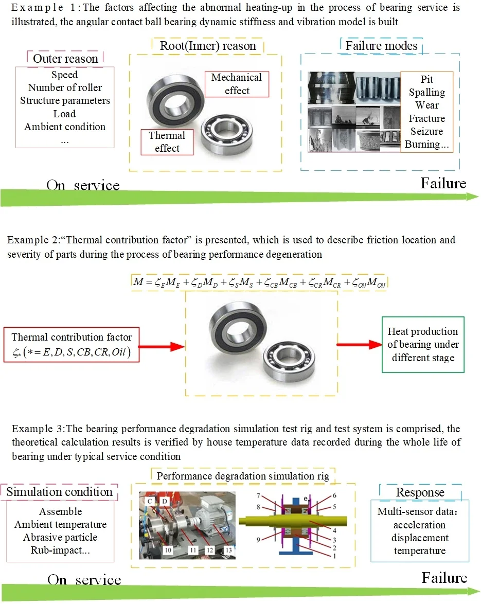
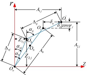
Assuming that outer ring is fixed, external (static) load acts on the inner ring of bearing, as illustrated in Fig. 1(a), there is relative displacement between inner ring, the contact angular changes from to , as shown in Fig. 1(b). and is relative displacement along axial direction and radial direction, respectively.
2.1.2. Rolling element force analysis
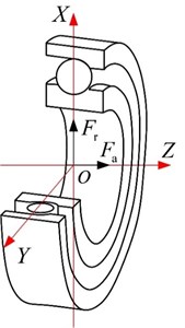
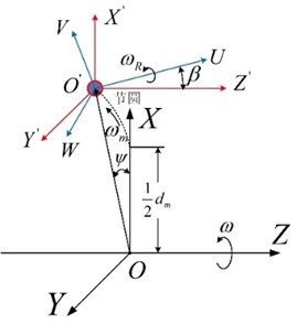
Considering centrifugal force and gyroscopic moment, mechanical properties analysis of ballis executed. As the bearing is running, ball center position changes owing to centrifugal force, thus, the contact angular between ball and inner or outer ring is different, connecting line of two raceway curvature centers turns into fold line, as depicted in Fig. 2. The location of ball center moves from to . is free contact angular between ball and inner or outer ring without load, and is contact angular between ball and inner or outer ring affected by centrifugal force. As for outer ring is fixed, its raceway curvature center keeps invariant, outer ring raceway curvature center transforms from initial location to .
Fig. 1Force analysis of angular contact ball bearing
a)
b)
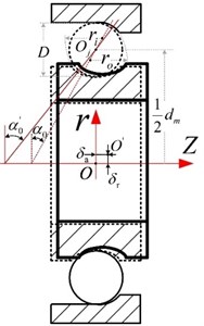
Fig. 2Angular position of ball j and position of ball center and raceway groove curvature center at angular position ψj with and without load
a) Azimuthal angle
b) Relative location of ball center and raceway curvature center before and after loaded
Before loaded, the distance between inner and outer ring raceway curvature center and is signed as , as illustrated in Fig. 2(b), whose expression is depicted as follows:
The distance between inner ring raceway curvature center that is fixed and ball center that is loaded is shown as follows:
Similarly, the distance between outer ring raceway curvature center that is loaded and ball center that is loaded is shown as follows:
where, and is normal contact deformation of inner and outer ring raceway.
According to Fig. 1(b), and is the relative axial displacement and radial displacement between inner ring and outer ring, respectively, the axial distance between inner ring raceway curvature center and outer ring raceway curvature center after loaded is represented as follows:
After loaded, the radial distance between inner ring raceway curvature center and outer ring raceway curvature center is shown as follows:
According to Fig. 2(b), some expressions are drawn as follows:
Based on the Pythagorean theorem, it is illustrated as follows:
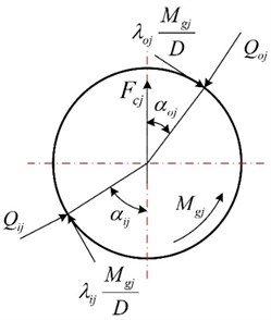
Supposing that friction is restricted in plane made up of bearing axis and ball center, the instantaneous location and load condition of the ball considering centrifugal force and gyroscopic moment are depicted in Fig. 3.
Fig. 3Instantaneous position and load of ball
a) Instantaneous location
b) Load condition
Assuming that the contact mode between inner ring and outer ring is point contact, and is Hertz contact force between inner ring and outer ring, respectively. Thus, the relationship between normal contact load and contact deformation of ball is explained as follows:
where, and is normal contact deformation between ball and outer ring or inner ring.
The equilibrium equations along horizontal and vertical direction are illustrated as follows:
Bringing Eq. (6) and (8) into Eq. (9):
where, in the assumption of “outer ring control”, , . is the centrifugal force of ball, is the gyroscopic moment of ball.
The centrifugal force is:
where, is the orbital speed of ball, is the rotational speed of inner ring around bearing axis.
The gyroscopic moment is:
where, is pitch angular of ball determined by Eq. (13); is the rotational speed around its axis; is inertia moment of ball:
where, .
For inner ring rotation, is expressed as follows:
is expressed as follows:
2.1.3. Bearing inner ring force analysis
The force condition of bearing inner ring enduring axial load and radial load is shown in Fig. 4.
Fig. 4Loads of inner ring
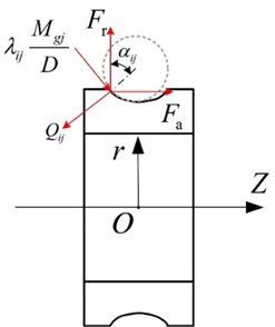
The contact force between inner ring and ball in certain moment is in balance, the corresponding force equilibrium equation is as follows:
where, is the number of ball.
Submitting Eq. (6) and (8) into Eq. (16):
2.1.4. Bearing body contact stiffness analysis
The contact stiffness between ball and inner ring or outer ring is arranged in series, but it is arranged in parallel between each ball. Therefore, axial contact stiffness influenced by axial load and radial contact stiffness [32] affected by radial load is shown as follows:
where, () is axial and radial component of normal contact stiffness between ball and inner ring; is axial and radial component of normal contact stiffness between ball and outer ring. Specific expression is as follows:
where, is normal contact stiffness between ball and inner or outer ring.
2.2. Angular contact ball bearing abnormal heat generation analysis
Based on bearing friction heat generation model, angular contact ball bearing abnormal heat generation model is established considering vibration load increment, surface topography diversification and inner radial clearance variation induced by contact surface damage, which including the related equations of EHL.
2.2.1. Angular contact ball bearing abnormal heat generation mechanism analysis
As angular contact ball bearing is under service, friction pair is wounded owing to contact fatigue accumulation, which results in increment of bearing vibration and friction moment, with the development of surface damage, bearing produces massive amount of heat. Hence, the factors having an effect on bearing abnormal heat generation are as follows:
(1) The increment of vibration load as a result of contact surface damage.
As bearing is under operation, contact load and contact frequency between bearing inner parts speed up, consequently, it enhances bearing inner heat production.
The integral vibration model of angular contact ball bearing is depicted in Fig. 5.
Fig. 5The mechanical diagram of bearing
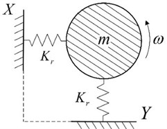
For single-degree-of-freedom system without damp, whose vibration equation is shown as follows:
where, is the displacement vector, which is expressed as follows:
where, () is displacement amplitude, which represents the maximum displacement away from the equilibrium position; , and is displacement amplitude belonging to low, medium and high frequency band, respectively.
(2) The development of surface topography.
Abrasive wear induced by spall in contact surface or abrasive contaminant in lubrication oil under angular contact ball bearing is running would accelerate the evolvement of contact surface roughness.
As surface topography decays to a certain extent, lubrication condition changes, the oil film thickness of contact surface between ball and raceway is inadequate to keep contact surface asperities of ball and raceway apart, thus, there is rub-impact between surface asperities of mating parts, which results in abnormal vibration and excessive heat production of bearing, it would cause poor lubrication, the “skid” accelerating bearing failure would appears after a further development.
Bearing lubrication state is determined by oil film lubrication parameter (film-thickness ratio) :
where, and is root-mean-square deviation of both surface roughness, respectively. They are arithmetic mean value of surface roughness , i.e. .
Lubrication oil affected by temperature in contact zone is treated as non-Newtonian fluid, whose viscosity and oil film thickness is illustrated as follows:
Owing to friction heat originated from bearing contact zone has little access to dissipate effectively, the temperature of lubrication oil would raise up. Hence, the relationship between lubrication oil viscosity and temperature is defined by viscosity-temperature equation:
where, is lubrication oil temperature, unit is ℃. , and are parameters related to the lubrication oil.
Influenced by thermal effect, the lubrication oil formed in contact zone between ball and outer or inner ring raceway, whose minimum oil film thickness [33] is expressed as follows:
where, is oil film thermal revised parameter of contact surface. is non-Newtonian fluid revised parameter. is minimum oil film thickness of isothermal Newton fluid.
Minimum oil film thickness of isothermal Newton fluid is obtained by adopting Hamrock-Dowson equation [34]:
where, is the non-dimensional parameter, is the surface average speed. is the non-dimensional material parameter. is viscosity-pressure index. is the non-dimensional load parameter. is the equivalent curvature radius, among which, negative sign is suitable for inner ring, positive sign is suitable for outer ring. is ellipticity.
Oil film thermal revised parameter is calculated utilizing Gupta equation [35, 36]:
where, is Hertz contact pressure. , is thermal conductivity in inlet, is temperature-viscosity coefficient of lubrication oil.
Non-Newtonian fluid revised parameter is calculated adopting Bair equation [37]:
where, is shear stress of lubrication oil. is exponent sign. is dynamic viscosity of lubrication oil [38].
(3) The alteration of clearance.
The working clearance changes caused by thermal expansion, the corresponding expression is shown as follows:
where, is inner radial clearance affected by axial force, is the variation of clearance due to thermal expansion, is the increment of ball diameter owing to difference in temperature.
As angular contact ball bearing is in service, although ambient temperature is constant, the bearing inner and outer ring would expand affected by friction heat generation, the variation of internal radial clearance is expressed as follows:
where, is inner ring temperature, is outer ring temperature, is reference temperature; is inner diameter of outer ring, is outer diameter of inner ring; is coefficient of linear expansion, for bearing steel, (1/℃).
As the temperature of inner ring is higher than that of outer ring, the expansion of inner ring results in decrease of inner radial clearance, it makes normal contact force and temperature in surface of mating parts ascend. Meanwhile, bearing radial clearance declines owing to difference in temperature, is negative.
As the temperature of outer ring is higher than that of inner ring, the expansion of outer ring results in increase of inner radial clearance, it makes vibration ascend Meanwhile, bearing radial clearance climbs up owing to difference in temperature, is positive.
The increment of ball diameter owing to thermal expansion is:
where, is ball temperature.
Combining Eqs. (28)-(30) to achieve variation of bearing inner radial clearance due to thermal effect.
2.2.2. Heat generation calculation
Heat generation in virtue of friction [4, 39] is shown as follows:
where, is the heat generation, W. is the total friction moment, N⋅mm. is the rotational speed, r/min.
According to Palmgren method [5, 40], the total friction moment of bearing is achieved by calculating load friction moment and viscous friction moment:
where, is the friction moment due to elastic hysteresis. is the friction moment due to differential sliding motion. is the friction moment due to spin-sliding motion. is the friction moment due to the contact between cage and ball. is the friction moment due to the contact between cage and inner ring guide face. is the friction moment due to the loss of oil film viscosity. The corresponding expression is shown as follows:
(1) The friction moment due to elastic hysteresis :
where, , is ball diameter, is pitch diameter, is free contact angular. is elastic hysteresis coefficient, for bearing steel. is number of ball. and is the contact load between ball and inner and outer ring raceway, respectively, which are determined by quasi-statics equation. As illustrated in Figs. 2-3.
(2) The friction moment due to differential sliding motion :
where, is sliding friction coefficient determined by lubrication state:
where, is semi-major axis of contact ellipse with the dimension is 1. is contact surface equivalent curvature radius between ball and inner or outer ring raceway, respectively. is integrated elastic modulus of mating contact body. is the curvature sum of mating contact body. Among which:
where, is the second kind complete elliptic integral:
(3) The friction moment due to spin-sliding motion :
where, is the semi-major axis of contact ellipse between ball and inner ring raceway.
(4) The friction moment due to the contact between cage and ball :
where, , is cage weight, unit is N. is sliding friction coefficient, for the friction between steel and bakelite.
(5) The friction moment due to the contact between cage and inner ring guide face :
where, is elastic modulus, unit isN/(mm2). is the speed of guidance ring relative to cage, unit israd/s. is the eccentricity of cage center relative to bearing center, unit is mm. is cage weight, unit isN.
(6) The friction moment due to the loss of oil film viscosity :
where, is viscosity-pressure coefficient of lubrication oil, unit is mm2/N. is lubrication-sufficient factor, which is equal to oil film lubrication coefficient. is oil film thickness in contact zone between ball and inner or outer ring raceway, unit is m.
Nevertheless, rolling bearing is the component with multiple friction pairs. In the operation of bearing, the mating parts surface rough is evolving due to abrasive wear, inner friction location and severity of bearing is fluctuant, which results in the time-variant of friction moment. Consequently, the revision is required to Eq. (32), as shown in follows:
where, is called as “thermal contribution factor”, which is the parameter considering friction location and severity of bearing synthetically.
2.3. Thermal resistance of angular contact ball bearing system
The heat transfer in bearing system is a complicated 3-D process in nature. Owing to bearing is a symmetric revolution solid, the assumptions are made for simplified calculation [41]:
1) The thermal flow is uniform distribution in radial direction and symmetrical distribution relative to axial direction. At any azimuth angle, the thermal transfer model of rolling element is 1-D thermal transfer process.
2) Heat source is the thermal flow produced by friction of mating parts of bearing, there is no external heat source.
3) During the process of heat transfer, the heat transfer between ball and inner ring and outer ring is main path, the heat generation is divided into mating parts according to scale of 1:1.
4) The thermal resistance of beating parts is independent with thermal flow direction, the material property of bearing parts is isotropic, the process of heat transfer is stable.
5) Ignoring the radiation heat transfer between bearing parts and to ambient air owing to temperature difference between bearing parts is small.
6) Air temperature is constant and identical. Neglecting cooling effect of lubrication oil under dry-lubricated or lightly lubricated condition.
7) Ignoring fit thermal resistance between outer ring and house, inner ring and shaft.
Therefore, thermal-conduction resistance and thermal-convection resistance of bearing during the course of heat transfer are shown as follows.
2.3.1. Thermal-conduction resistance
For angular contact ball bearing system, heat flow transfers between ball, inner and outer rings, shaft and house. The corresponding thermal resistance is classified into radial thermal-conduction resistance, axial thermal-conduction resistance and contact thermal-conduction resistance.
(1) Radial thermal-conduction resistance.
The thermal-conduction resistance along radial direction of ball is:
where, is ball diameter.
Inner ring, outer ring and house of angular contact ball bearing is regarded as thin circular ring with inner diameter , outer diameter and width , respectively. Its thermal-conduction resistance along radial direction [42] is:
Shaft is equivalent to cylinder with outer diameter and width , whose thermal-conduction resistance along radial direction [42] is:
where, is thermal conductivity of material.
(2) Axial thermal-conduction resistance.
Shaft and house is individually treated as flat-wall with section area and width at the moment of calculating their axial thermal-conduction resistance. The corresponding thermal-conduction resistance is achieved by flat-wall thermal-conduction resistance:
where, section area of shaft is . Section area of house is .
(3) Contact thermal-conduction resistance.
Assuming that contact zone between ball and inner or outer ring is Hertz point contact, whose size is far less than that of bearing. Considering the influence of contact zone size and motion, the model proposed by Muzychka [43, 44] is utilized to determine thermal-conduction resistance of contact zone:
where, and is semi-major and semi-minor axis of contact ellipse, respectively. is Peclet number. is thermal diffusion coefficient. is characteristic velocity.
In order to installation, the relationship of inner ring and shaft, outer and house is transition fit. According to literature [45, 46], the corresponding contact thermal-conduction resistance is:
where, is the thickness of gap between two contact surface. is nominal contact area in contact zone. is dimensionless actual contact area. is thermal-conduction coefficient of media (in general, air). is equivalent thermal-conduction coefficient of two contact body.
2.3.2. Thermal-convection resistance
There is a complex fluid-solid coupling zone in angular contact ball bearing, such as contact zone between inner ring and ball, contact zone between outer ring and ball, convection heat transfer would be dominant as lubrication oil is present. Besides, convection heat transfer would occur in region between house and ambient air.
(1) Convection heat transfer coefficient between shaft and ambient air.
Inner ring is connected to shaft, thus, bearing revolution is driven by shaft rotation. Taking shaft as relative fixed coordinate system, convection heat transfer process between shaft and ambient air is equivalent to ambient air skims over shaft surface with high speed. At present, this convection heat transfer asking help for shaft rotation is forced convection heat transfer. The convection heat transfer coefficient between shaft and ambient air is indicated as follows [47]:
where, is thermal conductivity of air. is characteristic size, is shaft diameter as convection heat transfer occurs in shaft surface. is Nusselt number, depicted as follows:
where, is Reynolds coefficient. is Prandt coefficient. is angular speed of shaft. is shaft diameter. is heat diffusion coefficient. is air dynamic viscosity. is air density.
(2) Natural convection heat transfer between house and ambient air.
The house is cylindrical structure, the convection heat transfer process between its external surface and ambient air is treated as natural convection heat transfer due to relative lower motion speed.
Convection heat transfer coefficient [42] between external surface of house and ambient air is:
where, is ambient temperature of house. is house temperature.
(3) Convection heat transfer coefficient between ball or ring and lubrication oil.
There would be heat exchange between fluid and ring or rolling element surface as fluid passes through the house and rolling element surface. According to Harris [48], the convection heat transfer coefficient during the heat transfer process between rolling element and lubrication, in addition, ring surface and lubrication is shown as follows [48]:
where, is thermal conductivity of lubrication oil. is Prandtl number of lubrication oil. is Reynolds number, is kinematic viscosity of lubrication oil, is characteristic length. In the case of calculating heat loss from ball to lubrication, is ball orbital revolution speed, is ball diameter; in the case of calculating heat loss from ring to lubrication, is ring rotation speed, is ring diameter.
Thermal-convection resistance of each convection heat transfer coupling is shown as follows:
(1) Thermal-convection resistance between shaft external surface and ambient air.
As calculating thermal-convection resistance between shaft external surface and ambient air, the shaft external surface is simplified to cylindrical surface with external diameter and width . Thus, the heat exchange area is , the corresponding radial thermal-convection resistance between shaft external surface and ambient air is:
(2) Thermal-convection resistance between shaft end face and ambient air.
As calculating thermal-convection resistance between shaft end face and ambient air, the exchange area is , the corresponding thermal-convection resistance between shaft end face and ambient air is:
(3) Thermal-convection resistance between house external surface and ambient air.
As calculating thermal-convection resistance between house external surface and ambient air, the house external surface is simplified to cylindrical surface with external diameter and width . Thus, the heat exchange area is , the corresponding thermal-convection resistance between house external surface and ambient air is:
(4) Thermal-convection resistance between house end face and ambient air.
As calculating thermal-convection resistance between house end face and ambient air, the house end face is simplified to circular ring with external diameter and inner diameter . Thus, the heat exchange area is , the corresponding thermal-convection resistance between house end face and ambient air is:
(5) Thermal-convection resistance between ball and ambient air.
As calculating thermal-convection resistance between ball and ambient air, the ball is simplified to sphere with external diameter . Thus, the heat exchange area is , the corresponding thermal-convection resistance between ball and ambient air is:
(6) Thermal-convection resistance between inner or outer ring and ambient air.
As calculating thermal-convection resistance between inner or outer ring and ambient air, the ring is simplified to cylindrical surface with external diameter and width . Thus, the heat exchange area is , the corresponding thermal-convection resistance between inner or outer ring and ambient air is:
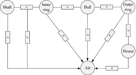
According to Eqs. (44)-(49) and (56)-(61), thermal resistance transfer path of bearing system is established, shown in Fig. 6. The heat generation in each friction coupling delivers to external environment through inner ring, outer ring and ball, ignoring the cooling effect of lubrication oil, convection heat transfer mainly occurs in several ways: on one hand, forced convection heat exchange between inner ring end face and ambient air, go a step further, shaft and ambient air, on the other hand, natural convection heat exchange between house and ambient air.
Fig. 6Thermal resistance transfer of bearing
2.4. Bearing system thermal network model with steady temperature
2.4.1. Thermal network node arrangement
Ignoring seal and edge chamfer structure, bearing system is separated into 17 nodes, as depicted in Fig. 7. Among which, bearing body has 7 nodes, shaft has 4 nodes in different position and 1 node of external environment. Node definition and meaning is illustrated in Table 1.
Table 1Description of nodes arrangement
Node No. | Location |
1 | House |
2 | Outer ring |
3 | Ball |
4 | Inner ring |
5, 6, 7 | Shaft |
8 | Air |
9, 10 | Contact zone between ball and outer/ inner ring |
11 | Outside surface of house |
12 | Contact surface between house and outer ring |
13 | Inner surface of outer ring |
14, 15 | Contact surface between ball and outer/inner ring |
16 | Outer surface of inner ring |
17 | Contact surface between shaft and inner ring |
2.4.2. Numerical solution
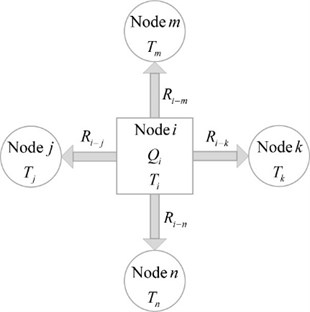
When calculating steady temperature field utilizing thermal network model, supposing that the heat flow in inlet is equal to that in outlet of node , as illustrated in Fig. 8. Consequently, according to heat flow balance theory, the balance equation of steady status heat transfer in 2-D system is shown as follows:
where, is temperature of node , is adjacent nodes, is thermal resistance of adjacent nodes, is heat generation of node .
Fig. 7Node thermal network model
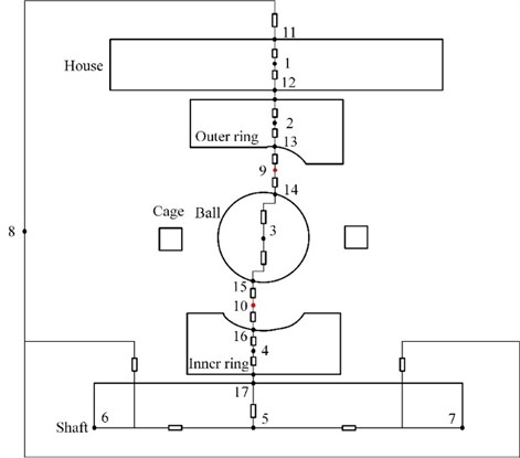
Fig. 8Diagram of node heat transfer mechanism
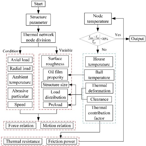
2.4.3. Calculation process
According to Eq. (62), the thermal balance equation of thermal network system is obtained. In order to obtain node steady temperature of bearing system, considering bearing structure, surface topography feature and load characteristic, the bearing system steady temperature model is employed to conduct multi-level and coupling analysis on structural mechanics, heat generation and heat transfer (heat conduction and heat convection). Calculation procedure is depicted in Fig. 9. Among which, radial load is referred as vibration load obtained from tested signal over the whole life of bearing.
Taking environment temperature as initial value, firstly, bearing quasi-statics is executed to calculate motion relation and mechanics relation of bearing parts according to boundary condition and working condition. Secondly, friction power loss, thermal-conduction resistance and thermal-convection resistance are obtained. Finally, node temperature is achieved by solving the steady status heat transfer equation set. Friction power loss and thermal resistance are updated after making comparison between calculation value and test value of house temperature. Nest, the system structure size, load distribution and installation tightness are revised based on the calculation result of thermal deformation of parts and bearing clearance. If relative difference percentage between calculation value and test value of house temperature is less than set one, the calculation is over.
Fig. 9Calculation process of thermal analysis considering thermal-solid coupling effects
2.5. Angular contact ball bearing dynamic stiffness and vibration analysis model
2.5.1. Angular contact ball bearing dynamic stiffness analysis
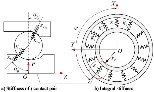
Dynamic stiffness of angular contact ball bearing refers to instantaneous stiffness during bearing is running, which is the reflection of ball-raceway contact characteristics. Considering Hertz contact and elastohydrodynamic lubrication, dynamic stiffness model of angular contact ball bearing [1] is derived by the establishment of ball-raceway Hertz contact model and oil film stiffness model.
Bearing stiffness model is depicted in Fig. 10. Bearing totally has contact coupling, each one is consist of a ball and its mating ring. Stiffness of each contact coupling is composed of ball-raceway contact stiffness and oil film stiffness in tandem, as shown in Fig. 10(a). Hence, bearing integral stiffness is consist of contact coupling stiffness in parallel.
Stiffness of ball-ring in single contact coupling is:
Thereinto, contact stiffness is illustrated in Eq. (8). In accordance of elastohydrodynamic lubrication theory, oil film stiffness of angular contact ball bearing is determined by minimum oil film thickness [49]. Oil film stiffness in contact zone of ball and inner/outer ring is derived according to Eq. (31):
Consequently, the component stiffness along radial and axial direction of single contact pair is [50]:
The whole radial and axial stiffness of bearing is:
Fig. 10Diagram of bearing radial stiffness
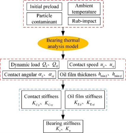
In the light of above explanation, some parameters are demanded to calculate bearing stiffness, such as dynamic contact load and , mean speed and in contact zone between ball and inner/outer ring, contact angular and between ball and inner/outer ring, oil film thickness and in contact zone between ball and inner/outer ring. The bearing system thermal analysis model based on elastohydrodynamic lubrication is employed to acquire parameters needed to compute bearing stiffness in accordance to working condition. The calculation routine is depicted as follows.
2.5.2. Angular contact ball bearing vibration analysis
Radial displacement of bearing inner ring is sum of relative radial contact deformation and radial working clearance , which is shown as follows:
Thereinto:
According to Eq. (34):
Fig. 11Calculation process of bearing stiffness
3. Test rig and result analysis
Angular contact ball bearing system thermal analysis model is verified utilizing house temperature test value under typical condition.
3.1. Angular contact ball bearing system multi-sensor response test method
(1) Bearing service performance degradation simulation test rig.
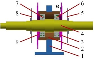
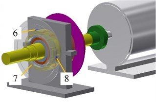
As introduced in literature [51], the bearing vibration data and house temperature over the whole life under excessive preload is obtained adopting micro-turbine bearing-rotor system test rig, as shown in Fig. 12, the rotor is supported by two angular contact ball bearing, which is coupled to an AC motor drawing aid from the flexible coupling. Thus, it can realize operation at different speeds. Tested bearing and contrast bearing connected to tube-shaped house via end cover is installed at C, D of house, the house is bolted to the pedestal due to interference fit at the middle of house. As illustrated in Fig. 12(b), the relative distance between house and another end cover is designed as when the one fits to house tightly, which can cover the demand of various tightness due to the adjustment of axial distance between end cover and house, thus, the relative location of inner and outer rings is changed. The test method is shown in Fig. 13, there are 3 eddy current transducers uniform distributed along circumference direction of house, the relative distance between end cover near test bearing and house is modified by adjusting the bolts. The average of 3 displacement values is employed as relative distance.
Fig. 12Test equipment: 1) pedestal, 2) house, 3) end cover 1, 4) shaft, 5) disc 1, 6) tested bearing, 7) contrast bearing, 8) disc 2, 9) end cover 2, 10) drum 1, 11) drum 2, 12) coupling, 13) AC motor
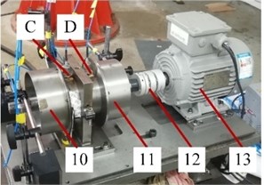
a) Test rig
b) Rotor structure
Fig. 13The relative distance test arrangement
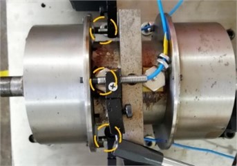
a) Entity map
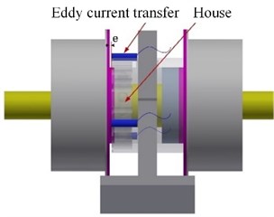
b) Sketch map
The tested bearing is 7208AC angular contact ball bearing, which composes bearing system with shaft and house, as depicted in Fig. 12(b). Bearing system structure parameter is shown in Table 2.
Table 2Structure dimensions of 7208AC angular contact ball bearing
Structure parameter | Sign | Value |
Inner diameter (mm) | 40 | |
Inner ring raceway diameter (mm) | 49.7 | |
Outer ring raceway diameter (mm) | 72 | |
Outer diameter (mm) | 100 | |
Pitch diameter (mm) | 61.3 | |
Ball diameter (mm) | 11.1 | |
Outer ring of house (mm) | 100 | |
Length of house (mm) | 70 | |
Ball quantity (–) | 21 | |
Ring/ball elastic modulus (Pa) | 2.19×10¹¹ | |
Ring/ball Poisson’s ratio (–) | 0.3 | |
Ring/ball density (kg/m3) | 7.83×10³ |
(2) Test system.
The run-to-failure test is conducted in overtight ( 0.682 mm), speed is 2400 r/min, the sign of bearing failure is the occurrence of fault or significant increment of vibration amplitude. Once bearing is out of service, the test is over. The duration of bearing run-to-failure is the whole life period. As depicted in Fig. 14, the shaft vibration data is recorded by RP6606XL eddy current sensor, sensor 1, 2 mounted near the shaft faraway from motor are utilized to record vertical vibration and horizontal vibration of shaft, sensor 5 is used to collect shaft vibration near motor. The tested and contrast bearing vibration data is real-time and efficient collected by means of CAYD115V-100A IEPE accelerometer mounted on the 3, 4 of house, respectively. Thermal couple is mounted evenly around circumference direction of house, sensor 6 is located forming 15 degree with vertical direction for avoiding the influence of bearing vibration test. Besides, a National Instrument compact Data Acquisition (NI Cdaq-9174) programmed with NI LabVIEW software is employed to record and real-time display the vibration signal. The record mode is continuous, sampling frequency of vibration signal is 25.6 Hz, sampling frequency of temperature is 2 Hz.
Fig. 14Location of sensors: 1) eddy current sensor 1, 2) eddy current sensor 2, 3) acceleration sensor 1, 4) acceleration sensor 2, 5) eddy current sensor 3, 6) thermal couple 1, 7) thermal couple 2, 8) thermal couple 3
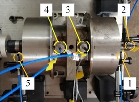
a) Entity map
b) Sketch map
3.2. Analysis of calculation value and test value
The test lasts 1815s. House temperature over the whole life of bearing is obtained via bearing multi-sensor response test rig. Environment temperature based on test value is introduced into model as initial value. After eliminating initial temperature, the comparison result between house temperature mean value of 3 test points during bearing performance degradation process and calculation value is shown in Fig. 15. The theoretical calculation results are obtained based on MATLAB R2020b.
Fig. 15Comparison between test result and calculation result of house temperature under overtight
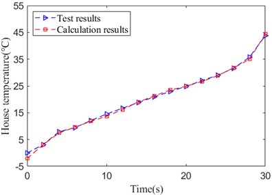
As shown in Fig. 15, there is a high consistency between house test temperature and calculation value over the whole life of bearing. Conducting error statistics of house temperature utilizing mean absolute percentage error [52] illustrated as follows:
where, and is test temperature and calculation temperature after eliminating the initial value. is time number of test temperature over the whole life of bearing.
The result is 1.26 %, which proves that the accuracy of angular contact ball bearing system steady temperature calculation model.
3.2.1. Contact characteristics evolution rule analysis over the whole life
The contact characteristics during the whole life of bearing under excessive preload mainly includes contact deformation, contact angular and contact stiffness.
Fig. 16Contact deformation
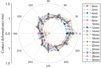
a) Contact zone between ball and outer ring
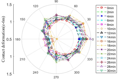
b) Contact zone between ball and inner ring
As shown in Fig. 16, contact deformation between ball and inner/outer ring has the same evolution rule, there is a little difference in amplitude. The curve behaves itself in the form of “D” in general, which is inclined to the location of 0° and 30°. At the location of 180° and 210°, the amplitude of contact deformation begins to decrease at 14min until the minimum at 18min.
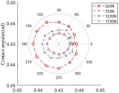
Fig. 17Contact angular
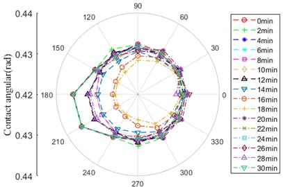
a) Contact zone between ball and outer ring
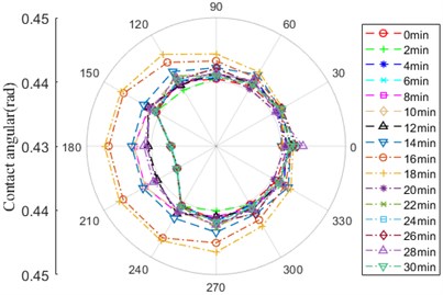
b) Contact zone between ball and inner ring
As depicted in Fig. 17, there is difference of contact angular between ball and inner/outer ring within the scope 150-240°. During the whole life of bearing, the curve of contact angular between ball and inner/outer ring has the opposite tendency, mainly including some phases: 0-6 min, 8-10 and 14 min, 16-18 min, 12, 20 and 28 min, 6 and 30 min. For example, the amplitude of contact angular between ball and outer ring is the maximum over the whole life of bearing at 0-6 min, at the same time, the amplitude of that between ball and inner ring is the minimum. The amplitude of contact angular between ball and outer ring begins to decrease at 8 minute until the minimum at 16, 18 min. After that, the amplitude of that gradually increases, the amplitude keeps steady at the location of 180° and 210° among 22-30 min. However, the amplitude of contact angular between ball and inner ring at 12min raises until it is closed to that at 20 min, on the contrary, the amplitude at 28 min is closed to that at 20 min.
Fig. 18 shows that the evolution rule of contact stiffness between ball and outer / inner ring has the same tendency, the curve shape is similar to “circle”, there is a little difference in the amplitude. The significant variation zone of amplitude is 60-300°, the amplitude with little fluctuation is minimum at 0-6 min. It begins to increase at 8 min until maximum at 16 and 18 min, among which, it moves down at 12 min. It is the degradation phase of contact stiffness at 20-30 min, which is the minimum at 30 min, nevertheless, it relatively increases at 28 min. Over the whole life of bearing, there is the maximum difference at the location of 180° and 210°.
Fig. 18Contact stiffness
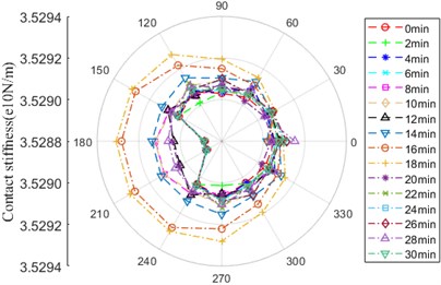
a) Contact zone between ball and outer ring
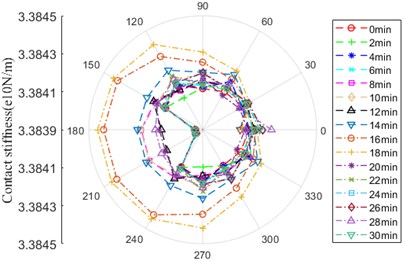
b) Contact zone between ball and inner ring
3.2.2. Oil film thickness and stiffness evolution rule analysis over the whole life
The diversification of temperature have an effect on the variation of lubrication oil viscosity and thickness, furthermore, it makes instantaneous contact characteristics change. The oil film thickness, stiffness and bearing dynamic stiffness is depicted from Fig. 19 to Fig. 21.
As shown in Fig. 19, the oil film thickness between ball and inner/outer ring has the same tendency expressing gradual decrease, the amplitude of oil film thickness between ball and outer ring is bigger than that between ball and inner ring. There is maximum variation of amplitude at 0-2 min, it keeps stable at another time.
Fig. 19Oil film thickness
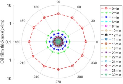
a) Contact zone between ball and outer ring
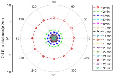
b) Contact zone between ball and inner ring
As shown in Fig. 20, the oil film stiffness between ball and inner/outer ring has the same tendency expressing itself as “D”, there is little difference in the amplitude. Over the whole life of bearing, it generally raise up, there is the maximum amplitude in 0° and 30°.
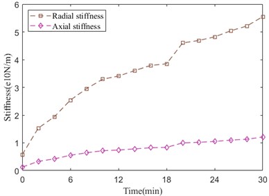
Fig. 21 shows the integral radial and axial stiffness evolution curves. As we can see, radial stiffness value alters more obviously than axial stiffness value, which are all rising up. At 18 minute, radial stiffness has an abrupt enlargement, next, it steps into a mild state. As shown in Fig. 18, contact stiffness in 18 minute drastically increases to maximum value, after that, the value decreases mildly, besides, the value of contact stiffness is far greater than that of oil film stiffness, therefore, the integral radial stiffness in 18 minute has an abrupt increment followed by a mild state due to the tandem relation between contact stiffness and oil film stiffness.
Fig. 20Oil film stiffness
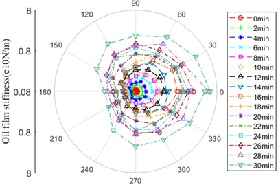
a) Contact zone between ball and outer ring
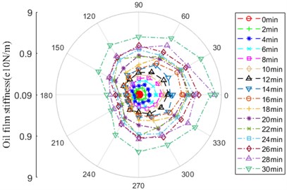
b) Contact zone between ball and inner ring
Fig. 21Stiffness
The radial clearance and displacement over the whole life of bearing is illustrated in Fig. 22. It shows that clearance has a negative correlation with house temperature, on the contrary, displacement has a positive correlation with house temperature. Clearance value is minus, the radial clearance reduces rapidly. However, there is a larger gap between the test value and calculation value of displacement at 0-12 min and 24-30 min. The reason is that the model is built without considering the temperature effect acting on fit between shaft and inner ring, fit between house and outer ring, shaft and house.
Fig. 22Radial clearance and displacement
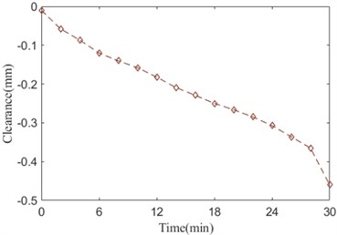
a) Radial clearance
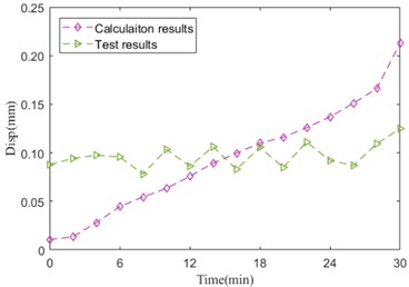
b) Radial displacement
3.2.3. Contact characteristics analysis under different conditions
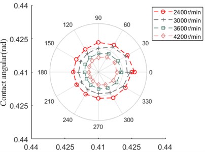
Based on the dynamic stiffness and vibration analysis model of bearing built in this paper, the contact characteristics and node temperature affected by preload or speed with/without EHL is illustrated as follows. Among which, the results shown in Fig. 23-Fig. 32 are calculated with EHL, the others are calculated without EHL. The speed keeps 2400 r/min as the preload increases, besides, the preload keeps 220 N as the speed adds up.
As shown in Fig. 23, the contact angular between ball and outer ring increases with the enlargement of axial preload, however, the contact angular between ball and inner ring has the opposite variation trend.
Fig. 23Contact angular
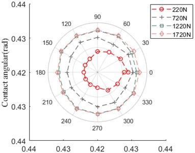
a) Ball and outer ring
b) Ball and inner ring
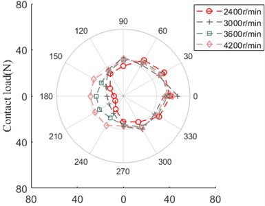
As shown in Fig. 24, the contact load between ball and outer/inner ring has the same evolution trend as axial preload increases, besides, the difference of their amplitude is approximate equal to zero.
Fig. 24Contact load
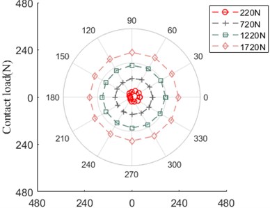
a) Ball and outer ring
b) Ball and inner ring
Fig. 25 illustrates that the dynamic stiffness along radial and axial direction of bearing affected by axial preload, which express themselves in the form of increasing firstly, then keeping steady gradually. With the increment of axial preload, the dynamic stiffness value of radial direction is larger than that of axial direction. In the initial growth phase of axial preload, the variation of dynamic stiffness along radial direction has a notable enlargement, then it slows down.
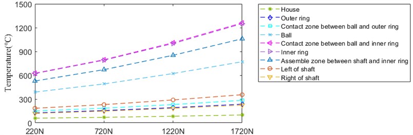
Fig. 26 depicts the temperature rise of nodes with the development of axial preload. The temperature of all nodes grows up in different degree. Among which, the temperature of inner ring and contact zone between ball and inner ring has the maximum expansion, whose value is similar.
Fig. 25Dynamic stiffness
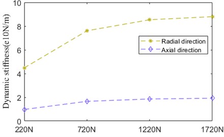
Fig. 26Temperature
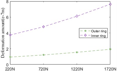
As indicated in Fig. 27, thermal deformation amount of inner ring and outer ring has the similar trend. The amplitude of inner ring deformation is much bigger than that of outer ring deformation in general.
Fig. 27Thermal deformation
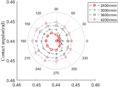
As shown in Fig. 28, the contact angular between ball and inner ring increases with the enlargement of speed, the contact angular between ball and inner ring has the opposite variation trend, it is obvious that the contact angular variation affected by axial preload has the opposite trend with comparison to that influenced by speed.
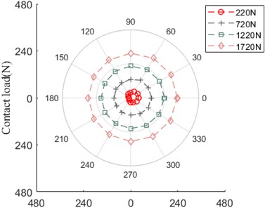
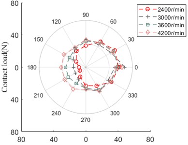
Fig. 29 advocates that the contact load between ball and outer/inner ring has the similar evolution rule and amplitude. From 2400 r/min to 3000 r/min, the curve shape behaves itself in the form of “square”, with the development of speed, the curve grows up ranging from 150° to 240°, which likes irregular “polygon”.
Fig. 28Contact angular
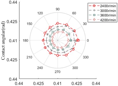
a) Ball and outer ring

b) Ball and inner ring
Fig. 29Contact load
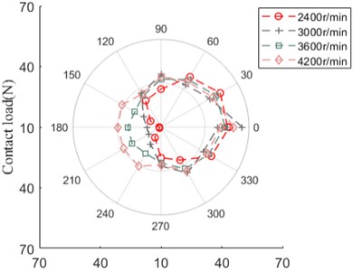
a) Ball and outer ring
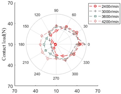
b) Ball and inner ring
As shown in Fig. 30, compared with the dynamic stiffness variation rule affected by axial preload, the dynamic stiffness along radial direction gently increase, which is similar to that along axial direction.
Fig. 30Dynamic stiffness
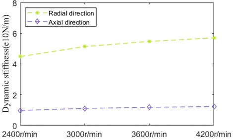
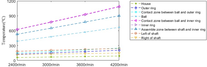
Fig. 31 depicts the temperature rise of nodes with the development of speed, whose amplitude is lower. The temperature of all nodes grows up in different degree. Among which, the temperature of inner ring and contact zone between ball and inner ring has the maximum expansion, whose value is similar.
Fig. 31Temperature
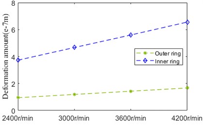
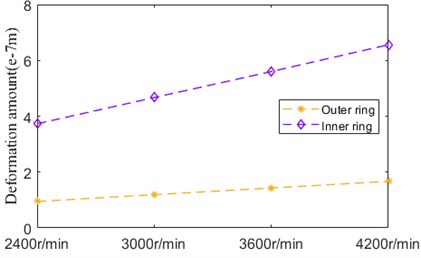
As indicated in Fig. 32, deformation amount of inner ring and outer ring influenced by speed has the similar trend, but the incremental quantity of inner ring is higher than that of outer ring. The amplitude of inner ring deformation is much bigger than that of outer ring deformation in general.
Fig. 32Thermal deformation
The contact angular, contact load, temperature rise and thermal deformation affected by speed ignoring EHL is shown in Fig. 33-Fig. 36. Compared with that affected by speed considering EHL, the variation rule of the above results is almost identical, which indicated the effect of lubrication oil on contact characteristics and thermal characteristics is weak dry-lubricated or lightly lubricated condition.
Fig. 33Contact angular
a) Ball and outer ring
b) Ball and inner ring
Fig. 34Contact load
a) Ball and outer ring
b) Ball and inner ring
Fig. 35Temperature
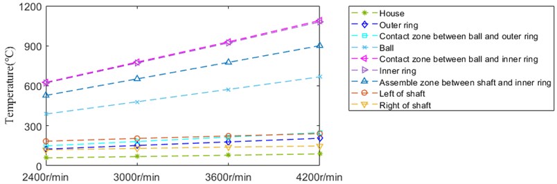
Fig. 36Thermal deformation
4. Conclusions
In this paper, bearing dynamic stiffness and vibration analysis model is built, house temperature achieved by bearing performance simulation test rig is utilized to verify the effectiveness of the model. Thus, it can be employed to realize theoretical analysis and experiment measurement of temperature and vibration during bearing performance degradation. The main conclusions are:
1) The factors affecting the abnormal heating-up in the process of bearing service is illustrated. Firstly, on the basis of bearing quasi-statics and elastohydrodynamic lubrication theory, the motion relationship and force relationship is determined by considering load and thermal factor. Next, bearing friction power loss is achieved adopting integral method, thermal-conduction resistance and thermal-convection resistance are also calculated. The steady temperature computed model of bearing based on thermal network method is established. Finally, the bearing dynamic stiffness and vibration analysis model is constructed regarding thermal-solid coupling effect. Besides, the typical calculation results are analyzed.
2) “Thermal contribution factor” is presented, which is used to describe friction location and severity of parts during the process of bearing performance degeneration, it is proved to exactly calculate bearing system temperature.
3) The bearing performance degradation simulation test rig and test system is comprised, the theoretical calculation results is verified by house temperature data recorded during the whole life of bearing under typical service condition. The comparison result has good consistency, which demonstrates the accuracy of angular contact ball bearing dynamic stiffness and vibration model.
4) The evolution rule of contact deformation and contact stiffness between ball and outer/inner ring over the whole life under excessive preload is the same, there is a difference in amplitude. So does the oil film thickness and oil film stiffness. However, the curve shape and amplitude of contact angular between ball and outer/inner ring over the whole life is different. The evolution trend of bearing dynamic stiffness generally behaves itself in the form of increment, besides, radial stiffness rapidly grows up.
5) The evolvement curve of contact angular affected by various preload and speed is opposite. The contact angular between ball and outer ring increases with the development of axial preload. However, it adds up between ball and inner ring as the speed increases. The contact load between ball and outer/inner ring has the same trend influenced by preload or speed with EHL. The variation of preload has bigger effect on temperature rise than speed change. The oil film has little influence on contact angular, contact load and temperature under dry-lubricated or lightly lubricated condition.
References
-
S. Deng, X. Dong, Y. Cui, and G. Hu, “Analysis of dynamic stiffness characteristics of double row angular contact ball bearings,” (in Chinese), Acta Armamentarii, Vol. 36, No. 6, pp. 1140–1146, 2015.
-
T. Someya, Journal-Bearing Databook. Springer-Verlag, 1989.
-
A. B. Jones, “A general theory for elastically constrained ball and radial roller bearings under arbitrary load and speed conditions,” Journal of Basic Engineering, Vol. 82, No. 2, pp. 309–320, Jun. 1960, https://doi.org/10.1115/1.3662587
-
T. A. Harris and M. N. Kotzalas, Rolling Bearing Analysis. New York: Taylor & Francis Group, 2006.
-
A. Palmgren, Ball and Roller Bearing Engineering. Philadelphia: S.H. Burbank, 1959.
-
X. Sheng, B. Li, Z. Wu, and H. Li, “Calculation of ball bearing speed-varying stiffness,” Mechanism and Machine Theory, Vol. 81, pp. 166–180, Nov. 2014, https://doi.org/10.1016/j.mechmachtheory.2014.07.003
-
M. F. While, “Rolling element bearing vibration transfer characteristics: effect of stiffness,” Journal of Applied Mechanics, Vol. 46, No. 3, pp. 677–684, Sep. 1979, https://doi.org/10.1115/1.3424626
-
L. Houpert, “A uniform analytical approach for ball and roller bearings calculations,” Journal of Tribology, Vol. 119, No. 4, pp. 851–858, Oct. 1997, https://doi.org/10.1115/1.2833896
-
H. Cao, “Time varying bearing stiffness and vibration response analysis of high speed rolling bearing-rotor systems,” (in Chinese), Journal of Mechanical Engineering, Vol. 50, No. 15, p. 73, 2014, https://doi.org/10.3901/jme.2014.15.073
-
T. C. Lim and R. Singh, “Vibration transmission through rolling element bearings, part I: bearing stiffness formulation,” Journal of Sound and Vibration, Vol. 139, No. 2, pp. 179–199, Jun. 1990, https://doi.org/10.1016/0022-460x(90)90882-z
-
T. C. Lim and R. Singh, “Vibration transmission through rolling element bearings, Part II: system studies,” Journal of Sound and Vibration, Vol. 139, No. 2, pp. 201–225, Jun. 1990, https://doi.org/10.1016/0022-460x(90)90883-2
-
T. C. Lim and R. Singh, “Vibration transmission through rolling element bearings. Part III: Geared rotor system studies,” Journal of Sound and Vibration, Vol. 151, No. 1, pp. 31–54, Nov. 1991, https://doi.org/10.1016/0022-460x(91)90650-9
-
T. C. Lim and R. Singh, “Vibration transmission through rolling element bearings, part IV: statistical energy analysis,” Journal of Sound and Vibration, Vol. 153, No. 1, pp. 37–50, Feb. 1992, https://doi.org/10.1016/0022-460x(92)90625-8
-
T. C. Lim and R. Singh, “Vibration transmission through rolling element bearings, part V: effect of distributed contact load on roller bearing stiffness matrix,” Journal of Sound and Vibration, Vol. 169, No. 4, pp. 547–553, Jan. 1994, https://doi.org/10.1006/jsvi.1994.1033
-
H.-V. Liew and T. C. Lim, “Analysis of time-varying rolling element bearing characteristics,” Journal of Sound and Vibration, Vol. 283, No. 3-5, pp. 1163–1179, May 2005, https://doi.org/10.1016/j.jsv.2004.06.022
-
D. Noel, M. Ritou, B. Furet, and S. Le Loch, “Complete analytical expression of the stiffness matrix of angular contact ball bearings,” Journal of Tribology, Vol. 135, No. 4, pp. 1–8, Oct. 2013, https://doi.org/10.1115/1.4024109
-
J. Zhang, B. Fang, Y. Zhu, and J. Hong, “A comparative study and stiffness analysis of angular contact ball bearings under different preload mechanisms,” Mechanism and Machine Theory, Vol. 115, pp. 1–17, Sep. 2017, https://doi.org/10.1016/j.mechmachtheory.2017.03.012
-
Z. Yang, B. Li, and T. Yu, “Influence of structural parameters and tolerance on stiffness of high-speed ball bearings,” International Journal of Precision Engineering and Manufacturing, Vol. 17, No. 11, pp. 1493–1501, Nov. 2016, https://doi.org/10.1007/s12541-016-0175-9
-
B. Fang, J. Zhang, K. Yan, J. Hong, and M. Yu Wang, “A comprehensive study on the speed-varying stiffness of ball bearing under different load conditions,” Mechanism and Machine Theory, Vol. 136, pp. 1–13, Jun. 2019, https://doi.org/10.1016/j.mechmachtheory.2019.02.012
-
S. Wang and Y. Xia, “Effect of the interference fit and axial preload in the stiffness of the high-speed angular contact ball bearing,” (in Chinese), Journal of University Science and Technology of China, Vol. 36, No. 12, pp. 1314–1320, 2006.
-
B. R. Jorgensen and Y. C. Shin, “Dynamics of Machine Tool Spindle/Bearing Systems Under Thermal Growth,” Journal of Tribology, Vol. 119, No. 4, pp. 875–882, Oct. 1997, https://doi.org/10.1115/1.2833899
-
D. Petersen, C. Howard, and Z. Prime, “Varying stiffness and load distributions in defective ball bearings: Analytical formulation and application to defect size estimation,” Journal of Sound and Vibration, Vol. 337, pp. 284–300, Feb. 2015, https://doi.org/10.1016/j.jsv.2014.10.004
-
X. Zhang, Q. Han, Z. Peng, and F. Chu, “A comprehensive dynamic model to investigate the stability problems of the rotor-bearing system due to multiple excitations,” Mechanical Systems and Signal Processing, Vol. 70-71, pp. 1171–1192, Mar. 2016, https://doi.org/10.1016/j.ymssp.2015.10.006
-
J. Zhang, B. Fang, J. Hong, S. Wan, and Y. Zhu, “A general model for preload calculation and stiffness analysis for combined angular contact ball bearings,” Journal of Sound and Vibration, Vol. 411, pp. 435–449, Dec. 2017, https://doi.org/10.1016/j.jsv.2017.09.019
-
W. Xiong, Z. Zhao, Y. Zhou, L. Lü, and Z. Hou, “Research on dynamic stiffness of ball bearings considering ferrule deformation and elastohydrodynamic lubrication,” (in Chinese), Zhongguo Jixie Gongcheng/China Mechanical Engineering, Vol. 26, No. 11, pp. 1421–1428, Jun. 2015, https://doi.org/10.3969/j.issn.1004-132x.2015.11.001
-
D. Sy Truong, B.-S. Kim, and J.-K. Park, “Thermally affected stiffness matrix of angular contact ball bearings in a high-speed spindle system,” Advances in Mechanical Engineering, Vol. 11, No. 11, p. 168781401988975, Nov. 2019, https://doi.org/10.1177/1687814019889753
-
X. Hao, J. Zhai, J. Liang, Y. Chen, and Q. Han, “Time-varying stiffness characteristics of roller bearing influenced by thermal behavior due to surface frictions and different lubricant oil temperatures,” Tribology International, Vol. 144, p. 106125, Apr. 2020, https://doi.org/10.1016/j.triboint.2019.106125
-
H. Wang, Q. Han, and D. Zhou, “Nonlinear dynamic modeling of rotor system supported by angular contact ball bearings,” Mechanical Systems and Signal Processing, Vol. 85, pp. 16–40, Feb. 2017, https://doi.org/10.1016/j.ymssp.2016.07.049
-
J. Liu, Y. Shao, and W. D. Zhu, “A new model for the relationship between vibration characteristics caused by the time-varying contact stiffness of a deep groove ball bearing and defect sizes,” Journal of Tribology, Vol. 137, No. 3, p. 03110, Jul. 2015, https://doi.org/10.1115/1.4029461
-
Y. Zhang, L. Xie, Z. Hu, and G. Lin, “Impact of elastohydrodynamic lubrication on contact stiffness between roller and raceway of ball bearings,” (in Chinese), Chinese Journal of Construction Machinery, Vol. 13, No. 3, pp. 206–211, 2015.
-
J. Liu and Y. Shao, “Dynamic modeling for rigid rotor bearing systems with a localized defect considering additional deformations at the sharp edges,” Journal of Sound and Vibration, Vol. 398, pp. 84–102, Jun. 2017, https://doi.org/10.1016/j.jsv.2017.03.007
-
X. Yun, X. Mei, G. Jiang, Y. Li, and S. Yuan, “Dynamic stiffness analysis and test method of high speed spindle angular contact ball bearing,” (in Chinese), Journal of Vibration, Measurement and Diagnosis, Vol. 39, No. 4, pp. 892–897, 2019.
-
J. Echávarri Otero, E. Guerra Ochoa, E. Chacón Tanarro, A. Díaz Lantada, and J. M. Munoz‐Guijosa, “Analytical model for predicting friction in line contacts,” Lubrication Science, Vol. 28, No. 4, pp. 189–205, Jun. 2016, https://doi.org/10.1002/ls.1325
-
B. J. Hamrock and D. Dowson, “Isothermal Elastohydrodynamic lubrication of point contacts: part III-fully flooded results,” Journal of Lubrication Technology, Vol. 99, No. 2, pp. 264–275, Apr. 1977, https://doi.org/10.1115/1.3453074
-
P. K. Gupta, H. S. Cheng, D. Zhu, N. H. Forster, and J. B. Schrand, “Viscoelastic effects in MIL-L-7808-type lubricant, part I: analytical formulation,” Tribology Transactions, Vol. 35, No. 2, pp. 269–274, Jan. 1992, https://doi.org/10.1080/10402009208982117
-
B. J. Hamrock and D. Dowson, “Isothermal Elastohydrodynamic Lubrication of Point Contacts: Part 1-Theoretical Formulation,” Journal of Lubrication Technology, Vol. 98, No. 2, pp. 223–228, Apr. 1976, https://doi.org/10.1115/1.3452801
-
S. Bair and W. O. Winer, “A simple formula for EHD film thickness of non-newtonian liquids,” Elastohydrodynamics – ’96 Fundamentals and Applications in Lubrication and Traction, Proceedings of the 23rd Leeds-Lyon Symposium on Tribology held in the Institute of Tribology, Department of Mechanical Engineering, Vol. 32, pp. 235–241, 1997, https://doi.org/10.1016/s0167-8922(08)70452-8
-
S. Bair, P. Vergne, and M. Querry, “A unified shear-thinning treatment of both film thickness and traction in EHD,” Tribology Letters, Vol. 18, No. 2, pp. 145–152, Feb. 2005, https://doi.org/10.1007/s11249-004-1770-y
-
C. Jin, B. Wu, and Y. Hu, “Heat generation modeling of ball bearing based on internal load distribution,” Tribology International, Vol. 45, No. 1, pp. 8–15, Jan. 2012, https://doi.org/10.1016/j.triboint.2011.08.019
-
K. Zhang and J. Li, “Analysis calculation of friction moment for the ball bearing,” (in Chinese), Bearing, Vol. 1, pp. 8–11, 2001.
-
R. A. Burton and H. E. Staph, “Thermally activated seizure of angular contact bearings,” A S L E Transactions, Vol. 10, No. 4, pp. 408–417, Jan. 1967, https://doi.org/10.1080/05698196708972200
-
K. Yan, N. Wang, Q. Zhai, Y. Zhu, J. Zhang, and Q. Niu, “Theoretical and experimental investigation on the thermal characteristics of double-row tapered roller bearings of high speed locomotive,” International Journal of Heat and Mass Transfer, Vol. 84, pp. 1119–1130, May 2015, https://doi.org/10.1016/j.ijheatmasstransfer.2014.11.057
-
Y. S. Muzychka and M. M. Yovanovich, “Thermal resistance models for non-circular moving heat sources on a half space,” Journal of Heat Transfer, Vol. 123, No. 4, pp. 624–632, Aug. 2001, https://doi.org/10.1115/1.1370516
-
F. Pouly, C. Changenet, F. Ville, P. Velex, and B. Damiens, “Investigations on the power losses and thermal behaviour of rolling element bearings,” Proceedings of the Institution of Mechanical Engineers, Part J: Journal of Engineering Tribology, Vol. 224, No. 9, pp. 925–933, Sep. 2010, https://doi.org/10.1243/13506501jet695
-
D. Zheng and W. Chen, “Thermal performances on angular contact ball bearing of high-speed spindle considering structural constraints under oil-air lubrication,” Tribology International, Vol. 109, pp. 593–601, May 2017, https://doi.org/10.1016/j.triboint.2017.01.035
-
B. Bossmanns and J. F. Tu, “A thermal model for high speed motorized spindles,” International Journal of Machine Tools and Manufacture, Vol. 39, No. 9, pp. 1345–1366, Sep. 1999, https://doi.org/10.1016/s0890-6955(99)00005-x
-
W. Tao, Heat Transfer. Beijing: Higher education press, 2019.
-
F. Kreith, “Convection Heat Transfer in Rotating Systems,” Advances in Heat Transfer, Vol. 5, pp. 129–251, 1969, https://doi.org/10.1016/s0065-2717(08)70130-8
-
B. J. Hamrock and D. Dowson, Ball Bearing Lubrication. New York: John Wiley and Sons Inc, 1981.
-
Y. Du, M. Qiu, X. Jiang, and J. Ma, “Stiffness calculation of high speed precision angle contact ball bearing,” (in Chinese), Bearing, Vol. 11, pp. 5–8, 2001.
-
X. Yun, N. Li, B. Wen, and Q. Han, “Study on stiffness of angular contact ball bearing and its evolution rule under excessive preload,” in IOP Conference Series: Materials Science and Engineering, Vol. 1081, No. 1, p. 012012, Feb. 2021, https://doi.org/10.1088/1757-899x/1081/1/012012
-
R. Fernandez Martinez, R. Lostado Lorza, A. A. Santos Delgado, and N. O. Piedra Pullaguari, “Optimizing presetting attributes by softcomputing techniques to improve tapered roller bearings working conditions,” Advances in Engineering Software, Vol. 123, pp. 13–24, Sep. 2018, https://doi.org/10.1016/j.advengsoft.2018.05.005
Cited by
About this article

This research work was supported by the National Key R&D Program of China (Grant No. 2018YFB2000300).
