Abstract
The contact angle and load distribution are important indicators for reflecting the operating condition of the angular contact ball bearing (ACBB). However, the raceway with local defect may cause serious diversification of contact angle and contact load. To analyze the effect of defect on bearing performances, a mechanical model considering the centrifugal force and gyroscopic moment of the rolling element is established for the defective ACBB. On this basis, the impacts of number of rolling elements on the load distribution and contact angle of defective ACBB have been evaluated. Also, the influence of defect size is taken into consideration. The results indicate that when a rolling element passes through the defect area, the rolling element will be partially or completely unloaded, while the others are loaded. This condition causes the load distribution and contact angle of ACBB are significantly influenced by the size of the defect. Under high-speed condition, the centrifugal force will aggravate the variation of the load distribution and contact angle in the defect area. The study in current work will be of great significant for revealing the failure mechanism and preventing premature failure for the ACBB.
1. Introduction
As the load-carrying and moving connecting units in rotating machinery, rolling bearings are the most impact- and wear-intensive components. In the manufacturing or long-term service, due to processing errors, constantly external or internal impact load, corrosion, wear and other reasons, the rolling elements and raceways of bearings are prone to produce the local defects, such as pitting, spalling, cracks, dents, and scratches [1]. The occurrence of local defects and their further deterioration will dramatically affect the operating performance of the bearing and significantly increase the vibration level of the bearing. Once the faults in the bearing system cannot be detected in time, the bearing and its corresponding mechanical system may result in serious failure or even catastrophic accident. Therefore, to prevent the bearing from failure deterioration and understand the failure mechanism of the bearing systems, it very essential to systematically study and analyze the impacts of local defect on the dynamic characteristics of rolling bearing. Also, the relevant theoretical analysis is of great significant to the quality inspection and condition monitoring of rolling bearing.
In the past decades, researchers have been conducted lots of works for the healthy rolling bearings. In 1901, Stribeck [2] firstly proposed a static analysis model for ball bearings based on the Hertz contact theory. Palmgren et al. [3] studied the deformation and contact load of the rolling bearing under axial, radial and moment. Jones [4] developed a quasi-static analytical model considering the inertia effect of rolling element. Subsequently, Harris [5] improved Jones’ model and developed a new quasi-static model for the rolling bearing. Their works was named as Jones-Harris (J-H) model. Generally, if the local defect occurs in the running of rolling bearings, the bearing contact characteristics and stiffness will change abruptly [6]. When the rolling element passes through the local defect area, the periodic impulse force will appear which may result in unacceptable vibration in rolling bearing system [7].
Patel et al. [8] established a dynamic analysis model for ball bearings with compound defects at the inner and outer rings, and solved the motion control equations of the bearing, the influence of rolling element and base vibration. Liu et al. [9]-[10] established a rolling bearing dynamic model based on the piecewise function at the local defect edge and the Hertz contact theory, studied different defect sizes, bearing contact mechanical properties and dynamic response under edge shape and plastic deformation. Singh et al. [11] used an explicit dynamic finite element method to study the change of the internal contact load of roller bearing with spalling at outer ring.
Most scholars pay close attention to the dynamic modeling of defect bearing and compare the vibration response of bearings with and without defect. However, there are few studies on the influence of local defect on dynamic characteristics, i.e. the contact angle and contact load between the elements and the bearing raceway.
Petersen et al. [12] proposed a static analysis model of ball bearing considering the rectangular defect on the raceway, and discussed the influence of the defect size on the bearing load distribution under different static loads. Li et al. [13] and Cheng et al. [14] studied the influence of defects on contact angle, contact load distribution and stiffness, respectively. Gao et al. [15] considered five defect positions on the raceway, established static and dynamic models of single-row angular contact ball bearings, and studied the influence of defects on bearing displacement, contact force, load distribution, stiffness and vibration response.
This paper proposes a mechanical model for the ACBB with the local defect on outer raceway based on J-H model. On the basis, the effects of the circumferential extent of local defect and the number of rolling elements on the ACBB contact angle and contact load distribution are systematically and innovatively studied under external load conditions.
2. Mechanical model of ACBB with local defect
The quasi-static model of ACBB with local defect is built by combining the local defect functions with the mechanical model of normal bearings.
2.1. Global and local coordinate systems
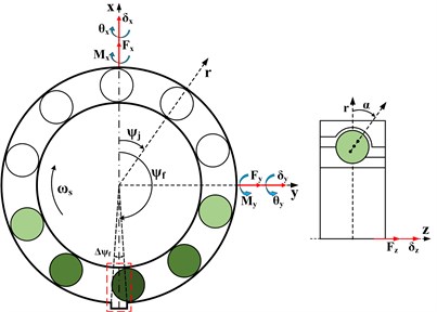
As shown in Fig. 1, three external forces about -axis, -axis and -axis and two moment loads about -axis and -axis are acting on the center of ACBB. Bearing is subjected to external forces and moment loads represented by force vectors . Hence, three translation displacement and two rotate angles are generated on the center of ACBB. The bearing displacements can be defined by a displacement vector, that is .
Fig. 1Global coordinate system of ACBB
When the inner raceway rotates at a constant angular speed , the angular speed of cage is given as bellow:
where is the ball diameter, is the pitch diameter and represents initial contact angle. The azimuth of the -th element is:
where is the number of rolling elements.
Fig. 2Displacement analysis of rolling elements passing through outer raceway defect
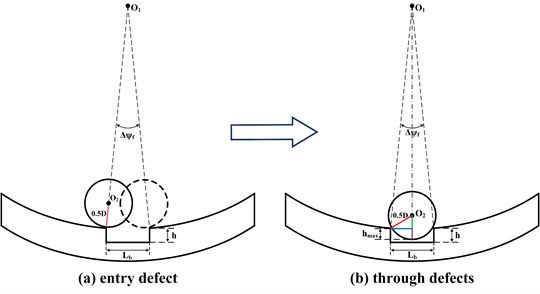
In this study, it is assumed that the outer raceway of ACBB has a local defect, as given in Fig. 1 and the enlarged view of the ball passing through the local defect area are shown in Fig. 2. The azimuth center of the local defect is in the coordinate system, and the circumferential angle extent of the defect is denoted by . When the element passes through the local defect area, the additional displacement excitation will be produced. The local defect can be described by the function derived by Petersen [12], that is:
where is the defect function of the rolling element at the azimuth angle , expresses the radius of the outer ring, and represents the radius of the rolling element.
2.2. Equilibrium of rolling elements
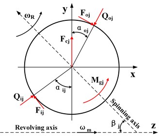
In the operation process, as shown in Fig. 3, each rolling element of the bearing is always in force equilibrium. Therefore, according to the relationships described in Fig. 3, the force balance equation for each rolling element is established as:
where 1, the gyroscopic moment of the bearing rolling element is equal to the friction force between the raceways.
Fig. 3Forces of the j-th rolling element
2.3. Equilibrium of equations of inner ring
On the above analysis, the contact forces , and the contact angles , can be calculated. Then, the force balance equations of the inner raceway can be established as bellow:
2.4. Calculation procedure of the theoretical model
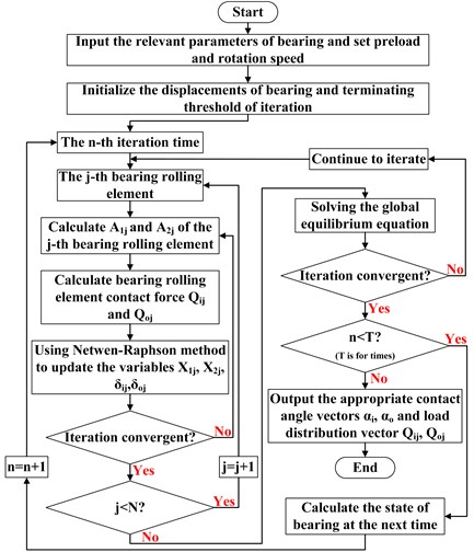
To solve the mechanical model of ACBB with local defect given above, the nonlinear equations of inner ring and rolling elements should be solve iteratively based on the Newton-Raphson method. The complete solution procedure for solving the proposed model is given in Fig. 4.
Fig. 4Calculation flow chart
2.5. Validation of the method
The model is validated in this section and the ACBB contact angle and contact load obtained by this method are compared with the results calculated by Wan [16].
The comparison results are shown in Table 1. The calculation results of the model in this paper are in good agreement with the calculation results of wan, which verifies that the mechanical model proposed in this paper is effective.
Table 1Verification results
Contact characteristic | Wan [16] | Proposed model |
Outer ring contact load | 488.97 N | 489.66 N |
Inner ring contact load | 76.57 N | 76.68 N |
Outer ring contact angle | 4.074° | 4.069° |
Inner ring contact angle | 37.70° | 37.64° |
3. Results and discussions
Based on the above model, the dynamic characteristics of ACBB B218 under different working conditions are studied and analyzed. The detailed structural parameters of B218 are shown in Table 2.
Table 2Structural parameters
Bearing parameters | Values |
Rolling Element diameter | 22.225 mm |
Outer raceway diameter | 147.7264 mm |
Inner raceway diameter | 102.7938 mm |
Number of rolling elements | 16 |
Radial clearance | 0.1 um |
Initial contact angle | 40° |
Outer raceway groove curvature coefficient | 0.5232 |
Inner raceway groove curvature coefficient | 0.5232 |
This section considers the outer raceway with different local defects ( 2°, 6°, 10°) and healthy bearing conditions, studies the bearing contact angle (, ) and contact load (, ) distribution changes with the number of bearing rolling elements (8, 10, 14, 16). The center angle of the local defect is located at the azimuth angle of 270°, the external load is (0, 1 KN, 5 KN, 0, 0) and the rotating speed is 5000 r/min.
Fig. 5Effect of number of rolling elements on contact angle of inner and outer rings under different defects: a) Δψf= 0°, b) Δψf= 2°, c) Δψf= 6°, d) Δψf= 10°
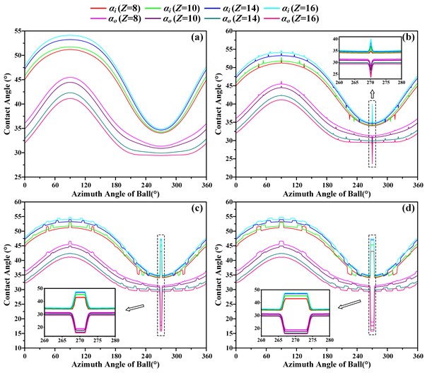
As shown in Fig. 5(a) and Fig. 6(a), when a healthy bearing is subjected to combined loads, the distribution of contact angles (, ) and contact loads (, ) between the rolling elements and the inner/outer ring changes sinusoidal with the azimuth angle of the rolling elements. In the case of the number of rolling elements is constant, the contact angle of the inner raceway is larger than the contact angle of the outer raceway, and the contact load of the inner raceway is smaller than the contact load of the outer raceway. As the number of bearing rolling elements increases, will gradually increase, while will gradually decrease. In addition, and will decrease with the increase of whether the load-bearing area or the non-load-bearing area, more importantly, the contact load distribution curve of the inner and outer rings will gradually become flat, which means that more rolling elements are located in the load-bearing area.
As shown in Fig. 5(b-d) and Fig. 6(b-d), the distribution of contact angles (, ) and contact loads (, ) of bearing with three different local defect sizes 2°, 6°, 10°. When the rolling element passes through the local defect area, the rolling element will neither suddenly drop into the defect region to release the elastic deformation, nor abruptly leave the defect area to obtain the elastic deformation. It can be seen from the figure that when the rolling elements enters into or leaves from the defect area, the contact deformation releasing and obtaining process is in a gradual manner, specifically the distribution of contact angle and the contact load will change in a gradual manner at the edge of the defect.
When the bearing is subjected to an external load, the contact deformation between the rolling elements at the local defect area and the inner/outer raceways will be reduced, the load will be partially or completely unloaded, and the load to be borne will be partially or fully distributed to rolling elements around it. However, the force and moment load under the inner ring of the bearing are unchanging, so the contact load of the rolling elements around the local defect area will increase, while the contact load of the rolling elements farther from the local defect area will decrease. It is certain that as the circumferential extent of local defects becomes larger and larger, part of the rolling elements will fall into the defect area, and this part of the rolling elements may regain the bearing capacity.
Fig. 6Effect of number of rolling elements on contact load of inner and outer rings under different defects: a) Δψf= 0°, b) Δψf= 2°, c) Δψf= 6°, d) Δψf= 10°
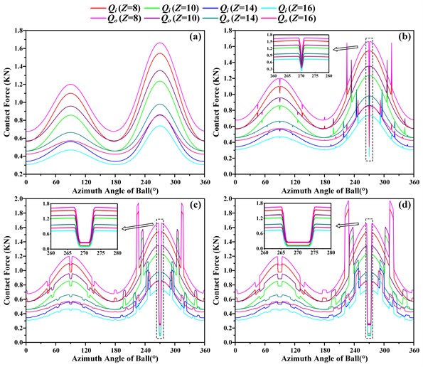
According to the geometry dimension calculation of bearing azimuth Angle between the roller spacing, When the number of rolling elements 16, the angular spacing between two adjacent rolling elements 22.5°, when 14 and 25.7 °, when 10 and 36 °, when 8 and 45°. The rolling elements roll into or out of the local defect area, , and , have local abrupt changes at every 22.5°, 25.7°, 36° and 45° distribution of the bearing azimuth, as the size increases, the occurrence of these mutations will become more and more obvious. When the rolling element rotation does not pass through the local defect area, the distribution of , and , is the same as that of the healthy bearing, which explains that the contact characteristic trend of the ACBB with local defect is the same as that of the healthy bearing, but when the rolling element passes through the local defect area Local mutation occurs.
4. Conclusions
Through the analysis, the following conclusions can be drawn:
1) For healthy angular contact ball bearings operating at high speeds, not all rolling elements are loaded, only the rolling elements in the load zone are subjected to external loads. When the cage rotates, the position and number of bearing rolling elements are constantly changing, which leads to real-time changes in the contact angle and contact load distribution.
2) When the rolling elements pass through the defect area, the rolling elements in the defect lose all or part of bearing capacity, the number of loaded rolling elements will vary, and the load will be redistributed to other rolling elements outside from the defect area.
3) As the local defects become larger, the contact angle and contact load mutation at the bearing defect will be more obvious.
4) The number of rolling elements has a very obvious effect on the contact characteristics of angular contact ball bearings. With an appropriate number of rolling elements, the distribution curve of the contact load will gradually become flat, indicating that more rolling elements of the bearing are located in the load-bearing area to carry the load.
References
-
J. Liu and Y. Shao, “Overview of dynamic modelling and analysis of rolling element bearings with localized and distributed faults,” Nonlinear Dynamics, Vol. 93, No. 4, pp. 1765–1798, Sep. 2018, https://doi.org/10.1007/s11071-018-4314-y
-
R. Stribeck, “Ball bearings for various loads,” Transactions of the ASME, Vol. 29, pp. 420–463, 1907.
-
A. Palmgren, Ball and Roller Bearing Engineering. Philadelphia: SKF Industries Inc, 1959.
-
A. B. Jones, “A general theory for elastically constrained ball and radial roller bearings under arbitrary load and speed conditions,” Journal of Basic Engineering, Vol. 82, No. 2, pp. 309–320, Jun. 1960, https://doi.org/10.1115/1.3662587
-
T. A. Harris, Rolling Bearing Analysis. 4th ed., New York: John Wiley and Sons, 2000.
-
D. Petersen, C. Howard, N. Sawalhi, A. Moazen Ahmadi, and S. Singh, “Analysis of bearing stiffness variations, contact forces and vibrations in radially loaded double row rolling element bearings with raceway defects,” Mechanical Systems and Signal Processing, Vol. 50-51, pp. 139–160, Jan. 2015, https://doi.org/10.1016/j.ymssp.2014.04.014
-
R. B. Randall and J. Antoni, “Rolling element bearing diagnostics – a tutorial,” Mechanical Systems and Signal Processing, Vol. 25, No. 2, pp. 485–520, Feb. 2011, https://doi.org/10.1016/j.ymssp.2010.07.017
-
V. N. Patel, N. Tandon, and R. K. Pandey, “A dynamic model for vibration studies of deep groove ball bearings considering single and multiple defects in races,” Journal of Tribology, Vol. 132, No. 4, pp. 1–10, Oct. 2010, https://doi.org/10.1115/1.4002333
-
J. Liu, Z. Shi, and Y. Shao, “A numerical investigation of the plastic deformation at the spall edge for a roller bearing,” Engineering Failure Analysis, Vol. 80, pp. 263–271, Oct. 2017, https://doi.org/10.1016/j.engfailanal.2017.06.019
-
J. Liu and Y. Shao, “An improved analytical model for a lubricated roller bearing including a localized defect with different edge shapes,” Journal of Vibration and Control, Vol. 24, No. 17, pp. 3894–3907, Sep. 2018, https://doi.org/10.1177/1077546317716315
-
S. Singh, U. G. Köpke, C. Q. Howard, and D. Petersen, “Analyses of contact forces and vibration response for a defective rolling element bearing using an explicit dynamics finite element model,” Journal of Sound and Vibration, Vol. 333, No. 21, pp. 5356–5377, Oct. 2014, https://doi.org/10.1016/j.jsv.2014.05.011
-
D. Petersen, C. Howard, and Z. Prime, “Varying stiffness and load distributions in defective ball bearings: Analytical formulation and application to defect size estimation,” Journal of Sound and Vibration, Vol. 337, pp. 284–300, Feb. 2015, https://doi.org/10.1016/j.jsv.2014.10.004
-
X. Li et al., “Analysis of varying contact angles and load distributions in defective angular contact ball bearing,” Engineering Failure Analysis, Vol. 91, pp. 449–464, Sep. 2018, https://doi.org/10.1016/j.engfailanal.2018.04.050
-
H. Cheng, Y. Zhang, W. Lu, and Z. Yang, “Research on time-varying stiffness of bearing based on local defect and varying compliance coupling,” Measurement, Vol. 143, No. 5, pp. 155–179, Sep. 2019, https://doi.org/10.1016/j.measurement.2019.04.079
-
S. Gao, S. Chatterton, P. Pennacchi, and F. Chu, “Behaviour of an angular contact ball bearing with three-dimensional cubic-like defect: A comprehensive non-linear dynamic model for predicting vibration response,” Mechanism and Machine Theory, Vol. 163, No. 9, p. 104376, Sep. 2021, https://doi.org/10.1016/j.mechmachtheory.2021.104376
-
C. S. Wan, Analytical Method of Rolling Bearing. China: Mchine Press, 1987.
About this article

