Abstract
Vibration-driven locomotion systems and mobile robots are widely used in different industries, in particular, for inspecting and monitoring the pipelines. Among the great variety of such robots designs, the ones based on the wheeled chassis and equipped with the vibratory drive are of the most widespread. The novelty of the present paper consists in substantiating the design parameters of the wheeled robot working under the vibro-impact conditions and driven by the crank-slider excitation mechanism. The main goal of this research is maximizing the robot average speed. While simulating the robot dynamic behavior, the numerical methods are used, in particular, the finite-element methods and the Runge-Kutta methods, which are implemented in the SolidWorks and MapleSim software. The obtained results presented in the form of time dependencies of the robot kinematic and dynamic characteristics can be of significant practical interest for the researchers and designers of the similar robotic systems.
Highlights
- The improved design of the wheeled robot working under the vibro-impact conditions and driven by the crank-slider excitation mechanism is developed and implemented for inspecting the pipelines.
- The corresponding simulation models of the robot's oscillatory systems are developed in the SolidWorks and MapleSim software.
- The robot locomotion conditions are modeled under different values of the impact gap. The optimal impact gap values ensuring the largest translational speed of the robot’s body are substantiated.
1. Introduction
Vibration-driven locomotion systems and mobile vibratory robots are currently of significant interest among scientists and designers all over the world. There is a great variety of the fields of their possible implementation: medical, military, mining, metallurgy, petroleum, manufacturing industries, etc. The present paper deals with improving the vibration-driven locomotion system for inspecting the pipelines and monitoring their internal surfaces, welds, couplings, etc. The similar problems have already been studied in numerous scientific papers, e.g., [1]-[6].
The novel design and the corresponding dynamic model of the in-pipe vibratory robot with the pneumatic drive is considered in [1]. Similar research on the dynamic behavior of the nonlinear locomotion system characterized by the asymmetric viscous friction is presented in [2]. The paper [3] is dedicated to studying the motion characteristics of the vibration-driven robot with the oscillating internal mass. In [4], the authors investigated the worm-like locomotion system with the electromagnetic drive. The double-mass vibratory robot actuated by the DC motor and rack-and-gear drive is considered in [5]. The self-propelled capsule system equipped with the electromagnetic vibration exciter is analyzed in [6]. All the locomotion systems mentioned above operate under the sliding motion conditions characterized by the asymmetric friction.
Unlike the papers [1]-[6] considered above, the wide range of scientific investigations are dedicated to the mobile robots equipped with the wheeled chassis. In particular, the paper [7] studies the influence of the wheeled robot’s design parameters on its dynamic behavior under different operational conditions. The thorough experimental investigations on the motion characteristics of the vibration-driven system based on the wheeled chassis are carried out in [8]. Most of the existent vibration-driven wheeled robots, in particular those considered in [7] and [8], are equipped with the inertial vibration exciters designed in the form of the unbalanced rotating masses. The possibilities of implementing the controllable multi-regime operational conditions of the vibratory machines with inertial exciters are thoroughly analyzed in [9].
The analysis of numerous investigations (e.g., [1]-[9]) has shown that the possibilities of implementing the crank-slider excitation mechanisms in the vibration-driven wheeled robots are not thoroughly investigated, especially under the vibro-impact operational conditions. Therefore, the previous authors’ papers were dedicated to studying the dynamic characteristics of the vibro-impact locomotion system with the twin crank-slider excitation mechanism [10], and analyzing the operational conditions of the vibratory compacting machine equipped with the crank-type drive [11]. The novelty of the present research consists in substantiating the design parameters of the wheeled robot working under the vibro-impact conditions and driven by the crank-slider excitation mechanism. The main goal of maximizing the robot average speed is to be analyzed on the basis of the numerical modeling and computer simulation using the following applied software: SolidWorks [12] and MapleSim [13].
2. Research methodology
2.1. General design and simulation model of the wheeled vibro-impact robot developed in the SolidWorks software
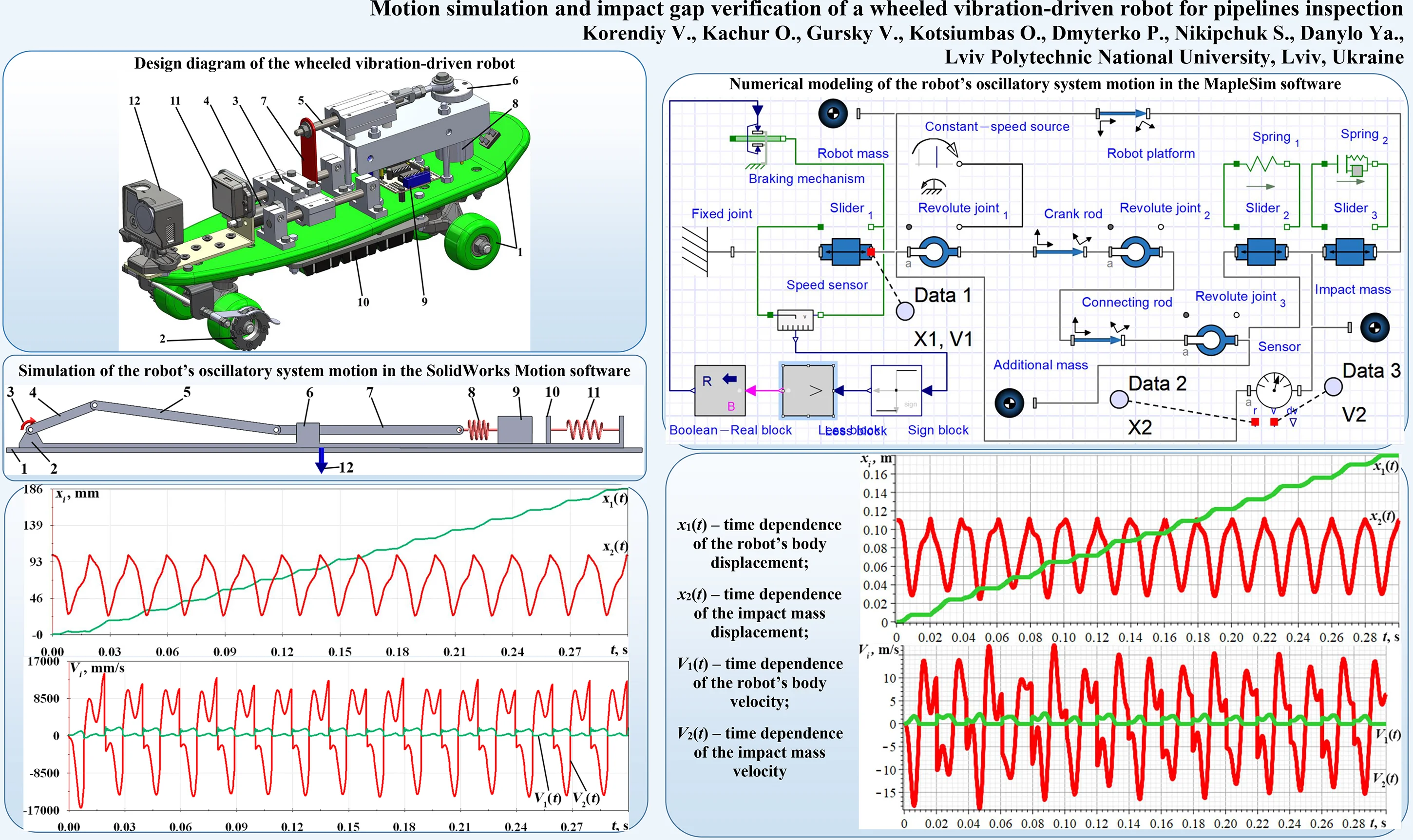
The improved design of the wheeled vibro-impact robot for pipelines inspection was developed in the SolidWorks software (see Fig. 1). The robot is based on the wheeled chassis 1 equipped with the special braking mechanisms 2 allowing only one-way rotation of the wheels. The robot is set into motion due to the sequential impacts of the oscillating body 3 upon the rubber damper 4 fixed to the wheeled chassis 1. The body 3 is connected to the sliding rod 5 of the driving crank (eccentric) mechanism 6 by the flat spring 7. The reciprocating motion of the sliding rod 5 performed due to the crank 6 rotation excites the oscillations of the impact body 3.
Fig. 1Design diagram of the wheeled vibration-driven robot
The crank (eccentric) 6 is driven by the DC motor 8 mounted on the wheeled chassis 1. In order to change the robot motion conditions according to the technological requirements, the machine is equipped with the remote control system 9 powered by the autonomous DC source 10. The robot motion parameters are continuously monitored by the accelerometer 11 sending the corresponding data to the computer for further processing and analysis. The robot’s main function of inspecting the pipelines and monitoring their internal surfaces (welds, couplings, etc.) is provided by the professional video camera 12 fixed on the front end of the wheeled chassis 1.
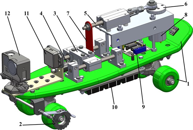
The simulation model of the robot’s double-mass vibro-impact system is presented in Fig. 2. The robot’s body 2 is placed upon the unmovable rough surface 1 and has the possibility to slide along the horizontal axis. The motor 3 sets the crank 4 into the rotary motion characterized by the constant angular velocity. The crank 4 is hingedly joined with the connecting rod 5 that provides the rectilinear oscillations of the sliding rod 7. The latter moves along the guide 6 fixed on the robot’s body 2. The sliding rod 7 is connected with the impact body 9 with the help of the spring 8. Therefore, the reciprocating motion of the sliding rod 7 provides the rectilinear oscillations of the impact body 9. The translational motion of the robot’s body 2 is characterized by the largest average velocities under the vibro-impact operational conditions. The latter take place due to the sequential impacts of the oscillating body 9 upon the impact plate 10 connected with the movable robot’s body 2 with the help of the spring 11. The interaction between the platform 2 and the rough horizontal surface 1 is simulated by the corresponding friction coefficients and the normal force 12 pressing the platform to the surface. The mentioned force takes its maximal value when the robot’s body 2 attempts to move leftward, while its zero value characterizes the platform state of rest or rightward motion. In such a case, the robot unidirectional sliding is ensured.
Fig. 2Simulation model of the robot’s oscillatory system developed in the SolidWorks Motion software
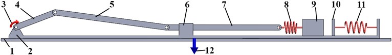
Fig. 3Simulation model of the robot’s vibro-impact system developed in the MapleSim software
2.2. Simulation model of the robot’s vibro-impact locomotion system developed in the MapleSim software
In order to carry out further numerical modeling of the robot operation, the simulation model of its oscillatory system was developed in the MapleSim software (see Fig. 3). The “Fixed joint” block denotes the initial position of the movable platform, which is simulated by the following blocks: “Slider 1” (wheels), “Robot mass”, “Robot platform” (chassis). The crank-slider excitation mechanism is modelled by the “Revolute joint 1”, “Constant-speed source”, “Crank rod”, “Revolute joint 2”, “Connecting rod”, “Revolute joint 3”, “Slider 2” blocks. The impact body and the impact spring are simulated by the “Impact mass”, “Slider 3”, and “Spring 2” blocks.
In order to restrict the backward motion of the robot’s body, the corresponding “Braking mechanism” block is used. The data obtained from the “Speed sensor” is analyzed by the series of the signal processing blocks “Sign block” (signum function), “Less block” (logical operator), “Boolean-Real block” (signal transformation). In such a case, the control system monitors the robot motion direction and send the signals to the “Braking mechanism” block for restricting the backward motion. The motion simulation results are registered by the following sensors: “Data 1” (absolute displacement and velocity of the robot’s platform), “Data 2” (displacement of the impact mass relative to the crank shaft), and “Data 3” (relative velocity of the impact mass).
3. Results and discussion
3.1. Simulation results obtained in SolidWorks software
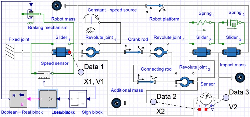
In order to perform further simulation of the robot locomotion in the SolidWorks and MapleSim software, let us introduce the following input parameters: the mass of the wheeled platform 30 kg; the mass of the impact body 3 kg; the stiffness coefficients of the corresponding springs (positions 8 and 11 in Fig. 2) 106 N/m, 108 N/m; the lengths of the rods 4, 5, 7 (see Fig. 2) 0.03 m, 0.08 m, 0.08 m; angular speed of the crank rotation 314 rad/s (the motor shaft rotates at the frequency of 3000 rpm). The initial impact gap, i.e., the smallest distance between the impact mass and the impact plate when the crank excitation mechanism remains at rest, is considered as the controllable parameter influencing the robot’s kinematic and dynamic characteristics. Fig. 4 presents the SolidWorks results of simulating the robot motion conditions when the initial impact gap is equal to zero.
The robot’s wheeled platform displacement reaches about 186 mm during the time period of 0.3 s, while the amplitude value of the impact body displacement is almost 40 mm (see Fig. 4). The maximal speed of the impact body reaches 16 m/s, and the one of the robot body is 1.85 m/s.
Fig. 4Time dependences of the movable platform and impact body a) displacements and b) velocities
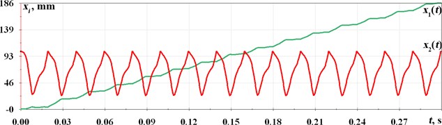
a)
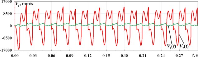
b)
3.2. Results of numerical modeling carried out in MapleSim software
In order to analyze the correctness of the results obtained in the SolidWorks Motion software, let us perform further simulation of the robot motion in the MapleSim software using the corresponding model considered above (see Fig. 3). The input model parameters are the same as those used previously. The obtained results are presented in the form of time dependencies of displacements and velocities of the robot’s movable platform and impact body (see Fig. 5). By the analogy with the results obtained above (see Fig. 4), it can be concluded that the average velocity of the robot’s platform is about 0.6 m/s, while its maximal value reaches 2 m/s; the amplitude values of the impact mass displacements and velocities are about 0.04 m and 16 m/s, respectively.
Fig. 5Time dependences of the movable platform and impact body a) displacements and b) velocities
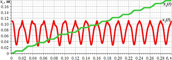
a)
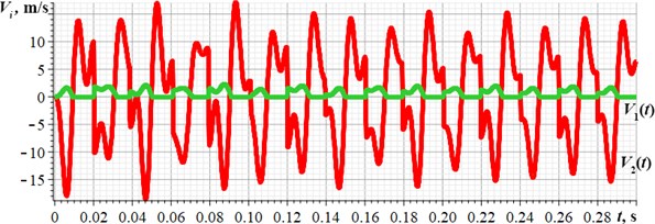
b)
3.3. Studying the impact gap influence on the robot average velocity
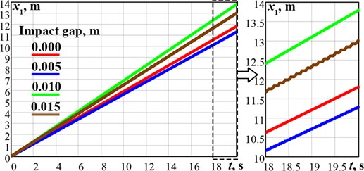
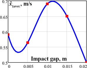
In order to analyze the possibilities of maximizing the robot average velocity, let us adopt the impact gap value as the changeable parameter influencing the kinematic and dynamic characteristics of the robot’s vibro-impact system. In our case, the impact gap characterizes the smallest distance between the impact mass and the impact plate when the crank excitation mechanism remains at rest. Previously, the robot’s vibratory system was designed and analyzed under the conditions when the impact gap was equal to zero. Fig. 6 presents the dependencies of the robot’s wheeled platform displacement and average velocity on the impact gap value ranging from 0 m to 0.02 m. The simulation results obtained in the SolidWorks and MapleSim software showed that the maximal value of the wheeled platform average velocity is about 0.7 m/s and takes place in the impact gap range of 0.01…0.012 m.
Fig. 6Dependencies of the robot displacement a) and average velocity b) on the impact gap value
a)
b)
4. Conclusions
The paper presents the enhanced design of the wheeled vibration-driven robot for inspecting the pipelines (Fig. 1). The robot is equipped with the crank-slider vibro-impact excitation mechanism driven by the DC motor, and the additional braking mechanism restricting the backward rotation of the wheels. The stepwise (discontinuous) translational motion of the robot is performed due to the sequential impacts of the internal oscillating body upon the rubber damper fixed to the wheeled chassis. The corresponding simulation models of the robot’s oscillatory systems are developed in the SolidWorks and MapleSim software. The robot locomotion conditions are numerically modeled under different values of the impact gap characterizing the smallest distance between the impact mass and the impact spring when the crank excitation mechanism remains at rest. The optimal impact gap value is in the range of 0.01…0.012 m, when the average velocity of the robot’s platform is about 0.7 m/s, and the amplitude values of the impact mass displacement and velocity reach 0.04 m and 15 m/s, respectively.
References
-
K. Ragulskis, M. Bogdevičius, and V. Mištinas, “Behaviour of dynamic processes in self-exciting vibration of a pipe robot,” Journal of Vibroengineering, Vol. 10, No. 3, pp. 397–399, Sep. 2008.
-
K. Ragulskis et al., “Investigation of dynamics of a pipe robot with vibrational drive and unsymmetric with respect to the direction of velocity of motion dissipative forces,” Agricultural Engineering, Vol. 52, pp. 1–6, Feb. 2021, https://doi.org/10.15544/ageng.2020.52.1
-
F. Becker, S. Börner, T. Kästner, V. Lysenko, and K. Zimmermann, “Spy bristle bot – a vibration-driven robot for the inspection of pipelines,” in 58th Ilmenau Scientific Colloquium, pp. 1–7, Sep. 2014.
-
R. R. Sattarov and M. A. Almaev, “Electromagnetic worm-like locomotion system for in-pipe robots: Novel design of magnetic subsystem,” in IOP Conference Series: Earth and Environmental Science, Vol. 315, No. 6, p. 062013, Aug. 2019, https://doi.org/10.1088/1755-1315/315/6/062013
-
G. Carbone, A. Malchikov, M. Ceccarelli, and S. Jatsun, “Design and simulation of Kursk robot for in-pipe inspection,” in SYROM 2009, pp. 103–114, 2010, https://doi.org/10.1007/978-90-481-3522-6_7
-
Y. Yan, Y. Liu, J. Páez Chávez, F. Zonta, and A. Yusupov, “Proof-of-concept prototype development of the self-propelled capsule system for pipeline inspection,” Meccanica, Vol. 53, No. 8, pp. 1997–2012, Jun. 2018, https://doi.org/10.1007/s11012-017-0801-3
-
I. A. Loukanov, V. G. Vitliemov, and I. V. Ivanov, “Dynamics of a vibration-driven one-way moving wheeled robot,” IOSR Journal of Mechanical and Civil Engineering, Vol. 13, No. 3, pp. 14–22, 2016, https://doi.org/10.9790/1684-1303051422
-
I. A. Loukanov and S. P. Stoyanov, “Experimental determination of dynamic characteristics of a vibration-driven robot,” IOSR Journal of Mechanical and Civil Engineering, Vol. 12, No. 4, pp. 62–73, 2015, https://doi.org/10.9790/1684-12426273
-
V. Gursky, P. Krot, V. Korendiy, and R. Zimroz, “Dynamic analysis of an enhanced multi-frequency inertial exciter for industrial vibrating machines,” Machines, Vol. 10, No. 2, p. 130, Feb. 2022, https://doi.org/10.3390/machines10020130
-
V. Korendiy, V. Gursky, O. Kachur, V. Gurey, O. Havrylchenko, and O. Kotsiumbas, “Mathematical modeling of forced oscillations of semidefinite vibro-impact system sliding along rough horizontal surface,” Vibroengineering PROCEDIA, Vol. 39, pp. 164–169, Dec. 2021, https://doi.org/10.21595/vp.2021.22298
-
V. Korendiy et al., “Kinematic and dynamic analysis of three-mass oscillatory system of vibro-impact plate compactor with crank excitation mechanism,” Vibroengineering PROCEDIA, Vol. 40, pp. 14–19, Feb. 2022, https://doi.org/10.21595/vp.2022.22393
-
K.-H. Chang, Motion Simulation and Mechanism Design with SOLIDWORKS Motion 2021. Mission, KS, USA: SDC Publications, 2021.
-
R. Müller, Modellierung, Analyse und Simulation elektrischer und mechanischer Systeme mit Maple™ und MapleSim™. (in German), Wiesbaden: Springer Fachmedien Wiesbaden, 2020, https://doi.org/10.1007/978-3-658-29131-0
About this article

