Abstract
Due to the lack of design standard and the difficulty of analysis, the floor vibration analysis of lightweight steel floors has received less attention than the analysis of typical floor structures. In this paper, the finite element model for lightweight steel floors is presented utilizing the rigid link and realistic support restraints. The rigid rink is used to solve the problem of difference in the centroid of beam, joist, and flooring material and to guarantee the same behavior of those members. Two different support restraints, all fixed restraint and mixture of fixed and released restraint, are used in the analysis. The finite element model is verified through the human impact loading test of the full-scale light-weight steel floors that have different joist condition and middle beam. The finite element analysis results indicate that the different joists having same moment of inertia yield similar natural frequencies, while the test results of full-scale floors show that the floor with the closed shaped joists yields higher natural frequency than the floor with open shaped joists. The test results also indicate that the finite element analysis using the mixture of fixed and released support restraint yields closer natural frequencies to those of actual floors.
1. Introduction
Modern architectural structures tend to have long span to satisfy economical and functional requirements, and light-weight steel floor structures are used more in accordance with the performance improvement of building materials and the development of the structural analysis techniques. Floor vibration problem is often issue in these long-span structures and light-weight steel floor structures because the natural vibration frequency of the floor is in relatively low frequency range, so the floor structure vibration due to the movement of the occupants is emerging as an important issue in the aspect of the serviceability [1-3].
There are two typical methods of construction using light-weight steel floor structures: steel houses and modular buildings, both of which were introduced around 2000’s in Korea [4, 5]. In steel house and modular buildings, floor structure is generally constructed with standard C or Z light gauge steel or rectangular pipes fabricated of cold-formed steel members. In addition, cement particle board or wood panel is used instead of concrete for floor slabs. Consequently, the mass of the floor structure is small compared to traditional concrete floor structure resulting that the local high-order mode vibration may appear very significant. In addition to steel houses and modular buildings, the height reducing floor systems are increasingly used to draw maximal floor areas within limited height. There are Slim Floor system and Smart Beam system [6] in height reducing floor systems, which are types of composite beam that are completed by pouring concrete on site to top of bottom flange of steel beam. These height reducing floor systems may be vulnerable of floor vibration due to small composite moment of inertia.
It is not easy to find a solution to the floor vibration once the structure is completed, because it is difficult to change the factors that may reduce floor vibration including mass, stiffness or damping of the floor. Therefore, the floor vibration problem can be coped with more effectively if the accurate floor vibration analysis is possible from the design phase of a structure. The vibration analysis of a light-weight steel floor structure is, however, often neglected due to the lack of design standard and difficulty of the analysis. Furthermore, studies on floor vibration studies have been mostly focused to concrete slab structure or composite deck slab [7, 8].
In this study, the finite element analysis model is presented to predict the vibration characteristics of a light-weight steel floor structure at design stage. The rigid link is suggested in the finite element analysis to solve the problem of difference in the centroid of beam, joist, and flooring material and to guarantee the same behavior of those members. Two different support restraints, all fixed restraint and mixture of fixed and released restraint, are also used to evaluate the behavior of the floor. Four full-scale light-weight steel floors that have different joist condition and middle beam are built to verify the finite element analysis model. The human impact loading test is performed to obtain the natural vibration frequencies of specimen floors, and the results are compared to those calculated from the finite element analysis.
2. Overview of the light-weight steel floor structure
In light-weight steel floor structure, columns and beams made of hot rolled-sections generally constitutes main frame, and C or Z light gauge steel joist are connected between beams by welding as in Fig. 1(a). Continuous fixing is effectively provided by screwing the floor members like cement particle board to the top of joist. Finishing materials are followed on top of floor members. In some cases, insulators are installed between joists. Fig. 1(b) shows an example of light-weight steel floor structures.
Fig. 1Light-weight steel floor
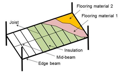
a) Schematic drawing
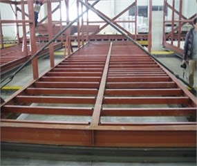
b) Example floor structure
3. Finite element analysis model of light-weight steel floor
3.1. Rigid link
Unlike concrete slab floor structure, light-weight steel floor structure is not an integrated system of structural elements (beams, joists, and flooring materials). Therefore, beam elements are used for beam and joist while plate elements are used for flooring material in finite element analysis modeling. In this case, it is necessary to constrain different elements meeting at one node appropriately to ensure the same behavior. Especially, it is important to secure the identical vertical behaviors of members because the floor vibration generates vertically. Furthermore, counter measures are necessary to resolve the phase difference because the central line positions of those elements are different.
In this study, rigid links are used to solve the problem of difference in the centroid of beam, joist, and flooring material and to guarantee the same behavior of members that meet at one node. A rigid link is a rigid bar element that provides a stiff connection between nodes in finite element model. This is accomplished by subordinating the degree of freedom of one or more nodes to the degree of freedom of a certain node; the certain node is called a master node, and the subordinated ones are called slave nodes. Types of rigid link are: method of limiting displacement and rotation by restraining relative motion as if the master nodes and slave nodes are connected by a 3-dimensional rigid body; a method to restrain relative motion as if master nodes and slave nodes are connected by a planar rigid body; and a method of restraining only displacement or rotation.
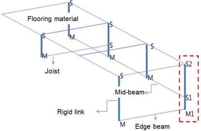
The flooring material and joist are fixed by screws in a light-weight floor structure, which is not considered to restrain rotational motion fully. Meanwhile, connection between the joist and beams are generally performed by welding, which prevents the rotation effectively. Considering these two different connection details, the rigid link that restrains rotation and displacement simultaneously is used for the convenience of modeling in this study. Fig. 2 shows the schematic of rigid links between floor material and joist, while Fig. 3 illustrates rigid links that connect edge beam, mid-beam, joist, and flooring material that have phase differences. In Fig. 3, M represents a master node and S means a slave node. Note that two rigid links must be used when two different slave nodes (S1 and S2) are connected to one master node (M1) as indicated in dotted box of Fig. 3. If two master nodes with respective slave nodes are assigned at the same location, an error will be produced from the overlap of the nodes.
Fig. 2Schematic of rigid link between flooring material and joist
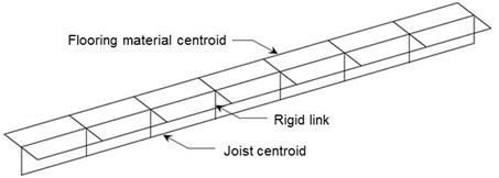
Fig. 3Rigid rinks connecting edge beam, mid-beam, joist, and flooring material with phase differences
3.2. Support restraints
The natural vibration frequency of a floor is calculated by the following equation [9, 10]:
where, is beam length, is the modulus of elasticity of the beam, is moment of inertia, is the mass per unit length, and is the variable depending on support restraint. is 9.869 for simply supported beams while 22.37 for fixed beams.
It is not appropriate to apply the above equation directly to actual floors because the support restraint of the beam-column joints is in-between of fixed and simply supported support. Similarly, it is very difficult to model the actual support conditions of beam-column connection in light-weight floor structures because members are connected by welding, bolt, and/or screws. In this study, two different support restraints, all fixed restraint and mixture of fixed and released restraints are investigated in the finite element analysis in order to represent the actual floors as summarized in Table 1.
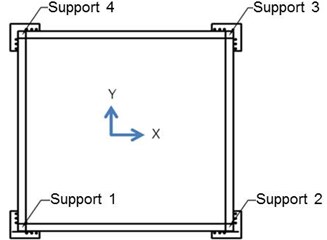
When all rotational and displacement degrees of freedoms of entire supports are restrained, it is termed as “All Fixed”; and when all rotational degrees of freedoms are freed but the displacement degrees of freedom are freed or restrained depending on the support locations, it is termed as “Fixed+Roller”. In the Fixed+Roller restraints, Support 1 in Fig. 4 is restrained in all three translational directions, and Support 2 is restrained in the vertical direction (-direction) and in the out-of plane direction (-direction). The diagonally opposite support, Support 4 in Fig 4, is restrained in the vertical direction and in the -direction. Support 3 is restrained in the vertical direction (-direction) only.
Table 1Rotation and displacement constraint conditions by points
Support restraints | Rotational degrees of freedom | Displacement degrees of freedom | |||
-direction | -direction | -direction | |||
All fixed | All supports | Restrained | Restrained | Restrained | Restrained |
Fixed+Roller | Support 1 | Freed | Restrained | Restrained | Restrained |
Support 2 | Freed | Freed | Restrained | Restrained | |
Support 3 | Freed | Freed | Freed | Restrained | |
Support 4 | Freed | Restrained | Freed | Restrained | |
Fig. 4Support restraints
4. Verification of finite element analysis model
4.1. Full-scale test floor specimens
Four full-scale floor specimens were fabricated for the verification of the finite element analysis model presented in this study. The size is same for all specimens as 3.3 m×3.3 m with the joist span of 400 mm. H-200×100×5.5×8 was used as the corner beam and the corner beams were bolt-connected to columns. Two of the specimens were built without center beam while the other two had a mid-beam of H-148×100×6×9 to investigate the stiffness increase effect. In addition, each specimen had two different type of joist: standard cold-formed C section or rectangular pipe section with two different moments of inertia. The standard cold-formed C-shape joist and the rectangular pipe joist were selected to have almost same moment of inertia as presented in Table 2. Fig. 5 shows the dimensions of the specimens.
Table 2Test specimens
Specimen | Joist | Existence of center beam | ||
Shape | Dimension | (cm4) | ||
SX | square pipe | 150×75×3.2 | 402.0 | No |
CX | cold-formed C-shape | 150×75×20×4.5 | 489.0 | |
SH | square pipe | 100×50×1.6 | 61.3 | Yes |
CH | cold-formed C-shape | 100×50×20×2.3 | 80.7 | |
The specimens were named as S (square pipes) or C (cold-formed C-shape) according to the joist shapes, and X (do not have) or H (have) depending on the existence of the hot-rolled steel beam at the center. Fig. 6 shows full-scale specimens used for the test. All specimens are finished with 900 mm wide cement particle boards.
Fig. 5Dimensions of specimens
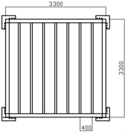
a) Specimen without a mid-beam
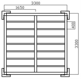
b) Specimen with a mid-beam
Fig. 6Test specimens
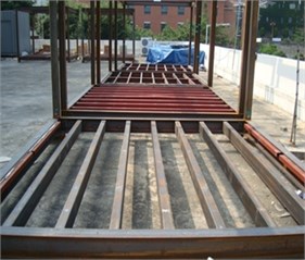
a) SX
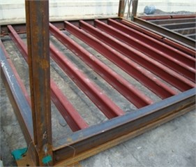
b) CX
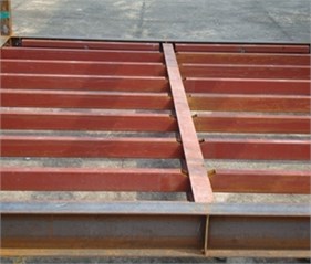
c) SH
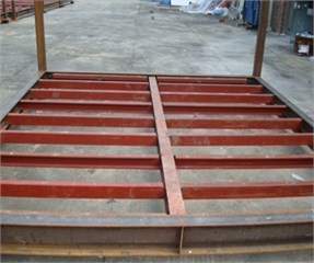
d) CX
4.2. Finite element modeling of full-scale test floor specimens
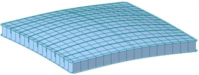
Midas/Gen [11] was used in this paper for the floor vibration analysis of light-weight steel floor structure. The mesh size for flooring material was set 200 mm×200 mm to obtain more accurate mode shape and natural vibration frequencies. Fig. 7(a) shows the final mesh configuration of the analysis model, and rigid links applied to all nodes are shown in Fig. 7(b). The rigid lines in Fig. 7(b) represent the location of joist, and the small number 1 at each node indicates the degree of restraints of each rigid link. Fig. 8 shows the finalized 3-dimensional finite element model for specimens SX and CH. The finite element models of specimens CX and SH are almost identical to specimens SH and CH, respectively, and thus omitted here.
Fig. 7Meshing and application of rigid links
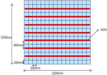
a) Meshing
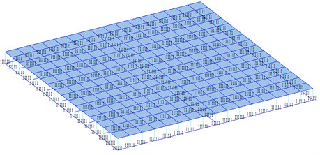
b) Application of rigid links
Fig. 8Finite element model of specimens
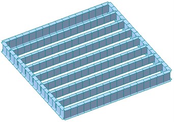
a) SX
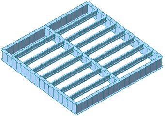
b) CH
4.3. Results of finite element analysis
Fig. 9 shows the first mode shape of specimens SX and SH obtained from the finite element analysis. The natural vibration frequencies in Fig. 9 are for the Fixed+Roller support restraint, which are quite different from the result of All Fixed support restraint despite the similar mode shape.
Fig. 9First mode shape and natural frequencies
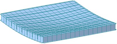
a) SX (natural frequency: 23.71 Hz)
b) CH (natural frequency: 25.36 Hz)
Table 3 summarizes the first mode natural frequencies of specimens calculated from the finite element analysis. The first mode natural frequencies under All Fixed support restraints appeared to be higher than those under Fixed+Roller support restraints for all specimens. It can be noted that the first mode natural frequencies under All Fixed support restraints are about 1.33 times greater than those under Fixed+Roller support restraints when there exist no mid-beam regardless of joist shapes; and 1.18 times with the existence of a mid-beam.
The increase in stiffness and the corresponding increase in natural frequency owing to a mid-beam were shown as expected under Fixed+Roller support restraints, but the opposite effect appeared under All Fixed support restraint. The reason seems that the mid-beam does not increase the stiffness but only adds the mass due to the confining effect of rotation and displacement at supports under All Fixed support restraint. Regardless of support restraints, the first mode natural frequency does not show much difference depending on joist shapes if the moment of inertia is similar. It can be noticed that the moment of inertia of the joist affects more on the floor vibration than the shape of the joist in the finite element analysis.
Table 3First mode natural frequency from finite element analysis
Specimen | Support restraint | |
All Fixed | Fixed + Roller | |
SX | 31.60 Hz | 23.71 Hz |
CX | 31.70 Hz | 23.67 Hz |
SH | 29.84 Hz | 25.16 Hz |
CH | 29.97 Hz | 25.36 Hz |
4.4. Experimental results
A human impact loading test on full-scale floor specimens was carried out to verify the validity of the finite element analysis model. The experiment was performed by applying the impact load by means of jumping of an adult person while acceleration data were measured at the center of floor (Fig. 10(a)). For the acceleration measurement, a servo-type accelerator ES-U2 of Kinemerics was used and a data-logger NetPod 4003 was used for data collection. Fig. 10(b) shows the measured acceleration time history of CX specimen.
Fig. 10Human impact loading test
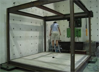
a) Test on specimen CX
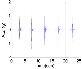
b) Measured acceleration time hisoty
Fig. 11 shows the power spectral density (PSD) of measured acceleration data to find the first mode natural frequency from the human impact loading test. The resulting first mode natural frequencies of four specimens are summarized in Table 4. It can be seen from Table 4 that the increase of stiffness owing to the mid-beam does not occur regardless of joist shape. That is, the measured first mode natural frequencies of specimens SH and CH with a mid-beam were lower than those of the specimens SX and CX. It can be concluded that the mass increase effect was greater that the stiffness increase effect if the mid-beam of hot rolled steel section is used. This finding is just as similar to finite element analysis result under All Fixed support restraints.
Unlike the finite element analysis result, however, the first mode natural frequencies of specimens SX and SH with square pipes joist ware measured higher than those of specimens CX and CH with cold-formed C-shape joist. It can be concluded that closed-section joist exhibits better floor vibration performance than open-section joist even though they have similar moment of inertia.
4.5. Comparison of analysis result and measured result
Table 5 compares the first mode natural frequencies between from the finite element analysis and from the experiment. It can be seen that the finite element analysis result under Fixed+Roller support restraint shows errors of 0.16 %-9.10 % compared to the experiment result, while All Fixed condition shows errors of 18.41 %-25.45 %. From this result, it can be conclude that the bolt connection for beam-column joint used in light-weight steel floor structures needs to be modeled with Fixed+Roller support restraint in order to represent the behavior of actual floor.
Fig. 11PSD of measured acceleration
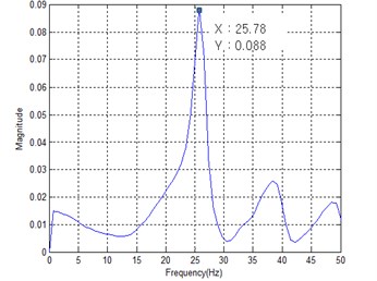
a) SX
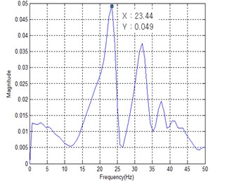
b) CX
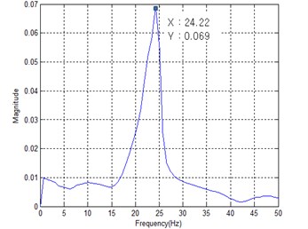
c) SH
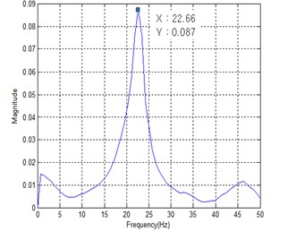
d) CX
Table 5Comparison
Specimen | All Fixed (A) [(A-C)/A]×100 | Fixed+Roller (B) [(B-C)/B]×100 | Measured (C) |
SX | 31.60 Hz (18.41 %) | 23.71 Hz (8.73 %) | 25.78 Hz |
CX | 31.70 Hz (25.45 %) | 23.67 Hz (0.16 %) | 23.44 Hz |
SH | 29.84 Hz (18.19 %) | 25.16 Hz (2.98 %) | 24.22 Hz |
CH | 29.97 Hz (23.08 %) | 25.36 Hz (9.10 %) | 22.66 Hz |
5. Conclusion
In this paper, a finite element analysis model was presented utilizing the support condition close to actual conditions along with the use of rigid link to analyze the vibration characteristics of light-weight steel floor. Rigid link was used to resolve the rigid motion and the centroid difference problems of the beam element-modeled edge beam and joist, and the plate element-modeled floor materials. Analysis was performed and compared for two support restraints: where both rotational and displacement degrees of freedom are restrained, and when rotational degrees of freedom are freed and displacement degrees of freedom are freed or restrained. For the verification of the suggested finite element analysis model, full-scale floor specimens with different joist shapes with and without a mid-beam were manufactured. The natural frequency was obtained from the human impact loading test, and compared with the finite element analysis result.
The finite element analysis result shows that the shape of floor joist does not affect much to the natural frequency of floor structure, while the experimental result of full-scale specimens shows that closed-section joist displays better performance in floor vibration than opens-section joist. In addition, the stiffness increase effect and natural vibration frequency increase owing to a central hot-rolled steel beam is not shown, which indicates that the mass increase effect is greater than the stiffness increase effect of the mid-beam. When the measured natural frequencies are compared to those of finite element analysis, results show that Fixed+Roller support restraints yields closer result to the experimental results by displaying 0.16 %-9.10 % error than All Fixed support restraints displaying 18.41 %-25.45 % error.
References
-
Wiss J. F., Parmele R. A. Human perception of transient vibration. ASCE Journal of Structural Division, Vol. 100, Issue ST4, 1974, p. 773-787.
-
BernardE. S. Dynamic serviceability in lightweight engineered timber floors. Journal of Structural Engineering, Vol. 134, Issue 2, 2008, p. 258-268.
-
Ebrahimpour A., Sack R. L. A review of vibration serviceability criteria for floor structures. Computers and Structures, Vol. 83, Issues 28-30, 2005, p. 2488-2494.
-
Hong S. G., Cho B. H., Chung K. S.,Moon J. Behavior of framed modular building system with double skin steel panel. Journal of Construction Steel Research, Vol. 67, Issue 6, 2011, p. 936-946.
-
Lawson M., Ogden R., Goodier C. Design in Modular Construction. CRC Press, Boca Raton, 2014.
-
Slimdek Manual. Tata Steel Construction, North Lincolnshire, 2012.
-
Lee D. G., Ahn S. K., Kim J. An efficient modeling technique for floor vibration in multi-story buildings. Structural Engineering and Mechanics, Vol. 10, Issue 6, 2000, p. 603-619.
-
Chen J., Xu R., Zhang M. Acceleration response spectrum for predicting floor vibration due to occupant walking. Journal of Sound and Vibration, Vol. 333, Issue 15, 2014, p. 3564-3579.
-
Design of Floors for Vibration: A New Approach. The Steel Construction Institute, Berkshire, 2009.
-
ISO 10137 Bases for Design of Structures – Serviceability of Buildings and Walkways Against Vibrations. International Organization for Standardization, 2007.
-
MIDAS/Gen-General Design System for Windows. Midas Information Technology, Seoul, 2001.
Cited by
About this article

This work was supported by the National Research Foundation of Korea (NRF) Grant funded by the Korean Government (MSIP) (NRF-2010-0023976).
