Abstract
With the continuous increase in the number of irregular buildings, ensuring the safety of building structures has become the primary concern. The study used finite element analysis to estimate the natural frequency of vibration of irregular building structures, and further designed a fuzzy control algorithm combined with magnetorheological dampers to improve their seismic performance. The research results showed that the longitudinal and transverse natural frequencies of Model 1 were 10.44 Hz and 10.51 Hz, respectively, while those of Model 2 were 10.31 Hz and 9.89 Hz, respectively. Using the fuzzy control method, the peak displacement of the building structure was reduced to 11.64 cm, and the peak acceleration was 7.9 m/s2. Comparing the open-plus-closed-loop control with open-loop control methods, it was found that although the fluctuation amplitude of the open-loop control method was relatively large, its control effect was poor, while the open-plus-closed-loop control methods had good overall control effect, with the peak acceleration of 8.26 m/s2 in the open-loop control. The study provides an accurate method for estimating the natural vibration frequency of irregular building structures and demonstrates the effectiveness of the designed fuzzy control algorithm in controlling building vibration.
1. Introduction
With the acceleration of global urbanization, high-rise buildings have gradually become the main structure of cities, not only because they have high land use efficiency and economic benefits, but also because their internal vertical and horizontal transportation systems can significantly reduce the communication costs between the internal areas of buildings. This development trend has played an important role in alleviating the scarcity of urban land and reducing construction costs. However, with the continuous growth of urban population, high-rise buildings often become densely populated areas, which may lead to huge casualties and economic losses in earthquake disasters. Therefore, the safety of high-rise buildings has become a crucial issue. Due to the fact that earthquake disasters mainly rely on the destruction of the ground and engineering structures, selecting appropriate geographical locations can avoid ground damage caused by earthquakes. Therefore, the key measure to prevent earthquake disasters is to enhance the structural strength of urban buildings to enhance their seismic resistance. The damage of engineering structures caused by earthquakes mainly depends on physical vibration and resonance structural damage. Although increasing the strength of building structures can to some extent avoid physical damage caused by vibrations, structural damage caused by resonance cannot be avoided through this method. If the natural vibration frequency of a building structure can be accurately calculated and its vibration frequency and amplitude can be controlled, the damage caused by seismic resonance of the building structure can be greatly reduced. The research innovatively utilizes fuzzy control (FC) algorithms to estimate the vibration frequency of building structures, and based on this, controls the vibration of building structures, thereby reducing the damage of earthquakes to irregular building structures in high-rise buildings. This has important practical significance for improving the safety of high-rise buildings in cities and reducing the impact of earthquake disasters on personnel and property. The research will be conducted from four parts. The first part is the current status of research on the natural frequency of building structure vibration. The second part is the research on the theory of Magnetic rheological damper (MRD) FC and the research on the MRD FC system of multi-layer buildings. The third part is the simulation experiment verification of control methods. The fourth part is a general overview of the research.
2. Related works
The vibration natural frequency (VNF) of materials has a great impact on the various properties of the structure. To study the impact of the VNF of irregular single-walled carbon nanotubes on the initial stress, Selim and El-Safty [3] deduced a new equation of motion and frequency equation, and used this equation to analyze the stress characteristics of single-walled carbon nanotubes. The results showed that the equations of motion could better reflect the vibration characteristics of single-walled carbon nanotubes. The frequency equation showed that the natural frequency (NF) of single-walled carbon nanotubes decreased with the increase of surface irregularity and initial stress parameters. To accurately evaluate the safety performance of stairs, Edlund and Ramakrishnan [4] established a coupled electromechanical system analysis model to analyze the NF of stairs under human flow, and collected the energy generated by stair vibration caused by human flow. The results showed that this model could estimate the VNF of stair and achieve the collection of vibration energy. To analyze the influence of different influencing factors on the NF of functionally graded materials under different boundary conditions, Moheimani and Dalir [5] used classical elastic theory at the nanoscale to study functionally graded materials. The results showed that at the nanoscale, non-localized effects have a significant impact on the NF of functionally graded materials. To adjust the performance of glassy carbon fiber composites, Singh et al. [6] proposed experimental and numerical technology methods, and measured the NF of composites using ABAQUS software. The outcomes denoted that the amount of glassy carbon fibers and the stacking mode would have a greater impact on the NF of composites.
Sun and Yuan [7] proposed a finite element analysis (FEA) model to analyze the free vibration problem of elastic free membranes. This model linearized the free vibration problem of elastic membranes into a linear equivalent problem and introduced local mesh refinement. The findings showed that this model could generate mode functions with the required accuracy of eigenvalues. Gomes and Donadel [8] developed a heuristic algorithm based control algorithm to complete the high acceleration life experiment of electric vibration screening and the vibration acceleration experiment of high acceleration stress screening. The algorithm designed two control systems, one based on fuzzy logic and the other based on traditional PID control. The outcomes showed that both control systems were used in the constant scanning experiment of acceleration and stress level control. All demonstrated excellent stability and accuracy. Yang et al. [9] proposed to use linear control theory to design an MRD controller and applied MRD to a segment assembly machine, replacing passive shock absorbers. They also used a fuzzy model to analyze the segment installer model. In this model, a fuzzy controller was used for disturbance observation, and the results showed that under MRD control, the acceleration of the segment assembly machine was reduced by 59.6 %. Azizi et al. [10] proposed an improved whale algorithm to optimize the fuzzy controller of nonlinear steel structure buildings under seismic excitation to improve the significant reduction of structural control response in high-rise buildings. The results showed that the improved method could effectively improve the control response of high-rise buildings.
In summary, although these studies focus on micro scale or local components, the obtained vibration characteristic information has guiding significance for understanding the vibration behavior of the overall structure. Through analyzing material properties, influencing factors, and using experimental and numerical techniques, it provides certain guidance for the design and optimization of larger scale buildings. Therefore, the study used the FEA method to analyze the VNF of irregular buildings, and there were also many seismic control methods for irregular building structures. The control system based on fuzzy logic is an excellent control system that can interact with other control systems. Therefore, the study proposed to use fuzzy logic control systems to improve the seismic performance of irregular building structures.
3. Calculation and control of VNF of building structure based on FC algorithm
The main content of this chapter is the estimation method for irregular building structures and the study of MRD FC system for multi-story buildings. It is divided into two sections. The first section is the estimation method for the VNF of irregular building structures, and the second section is the control research for the VNF of irregular building structures.
3.1. Estimation of VNF of irregular building structure based on FEA model
The VNF refers to the frequency at which a system vibrates without external forces. At this time, the vibration of the system is called free vibration. If the forced vibration frequency of the system under external forces is the same or close to the free vibration frequency of the system, it will lead to a significant increase in the vibration amplitude of the system, which is a resonance phenomenon. The occurrence of this phenomenon will cause great damage to the building structure. To make the NF of a building structure avoid the excitation source frequency, it is necessary to calculate the NF of the building structure, which is usually calculated in a mass spring system. When a building structure undergoes free vibration, there is no loss in the overall structural system. The sum of the kinetic and potential energy of the system is a constant, which can be expressed by Eq. (1):
where, means the kinetic energy of the system; denotes the potential energy of the system; refers to a constant. At this point, the vibration system of the building structure can be considered as a mass spring system, in which the potential energy conforms to Eq. (2):
where, stands for the elastic coefficient of the spring, and means the deformation of the spring, that is, the displacement of the building structure. The kinetic energy of the building structure at this time conforms to Eq. (3):
where, denotes the structural mass of the system, and indicates the speed. When the building structure is in a balanced position of vibration, the potential energy of the system is the smallest, 0, and the kinetic energy of the system is the largest, which can be expressed by Eq. (4):
where, represents the natural circular frequency of the system, and denotes the amplitude of the system. When the system is at its maximum amplitude, the kinetic energy of the system is the smallest, 0, and the potential energy of the system is the largest, which can be represented by Eq. (5):
Due to the overall energy conservation of the system, there exists Eq. (6):
Therefore, the NF of the structure conforms to Eq. (7) [11-12]:
To calculate the NF of a building structure using a FEA model, it is necessary to first model the building structure, study the use of Ansys software to complete three-dimensional FEA modeling of irregular buildings, and calculate the NF of the building structure. The calculation is shown in Fig. 1 [13-15].
Fig. 1Calculation of VNF of building mechanism using Ansys software
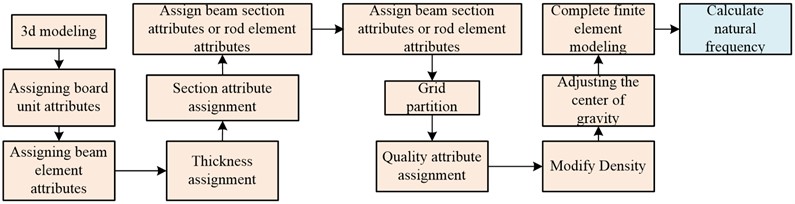
The calculation of the VNF of irregular building structure using Ansys software requires first constructing a three-dimensional modeling of the building structure. After completing the modeling, it is necessary to assign values to the beam and plate elements in the model. After assigning values to the beams and plates, it is also necessary to search for line elements corresponding to each bone material and beam pillar, and assign attributes to these line elements. After assigning attributes to the line elements, the FEA model can be meshed, when dividing the grid, the parts with larger areas and regular shapes will be divided into grids according to the specified size and shape. The parts with smaller areas or irregular shapes will be divided into secondary grids for subsequent calculations. If the problem of dividing irregular areas is not solved by secondary divisions, manual division can be used to complete the grid division. After the grid division is completed, weight attributes of each unit in the building structure need to be assigned. After the weight attribute is assigned, the material density of the building structure needs to be adjusted to make the overall state of the building structure coincide with the actual situation. Finally, after the boundary conditions are applied to the 3D model, the finite meta modeling of the irregular building structure can be completed. After the finite meta modeling is completed, the VNF of the building model can be extracted by using the modal analysis of Ansys.
3.2. VNF control of irregular building structure based on FC system
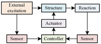
FC system is a structural form of digital control system, consisting of five parts: the first, second, third, fourth and fifth parts are fuzzy controller, interface, executing mechanism, controlled object and sensor, respectively. Among these five parts, the first part is the core of the FC system, and the structure of the FC system and fuzzy controller is shown in Fig. 2 [7, 16].
Fig. 2FC system and fuzzy controller structure
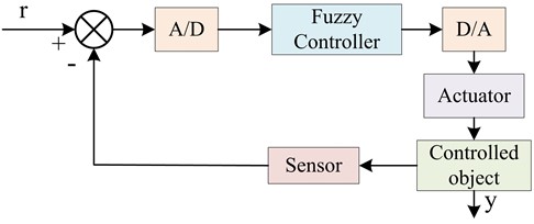
a) Fuzzy control system

b) Fuzzy control systestructurem
In a FC system, the result of fuzzy inference is a membership function. To serve as the control signal of the controller, it is necessary to select the most suitable and accurate value to represent the result of fuzzy inference. Usually, the maximum membership function method is used to determine the result of fuzzy inference, and each result of fuzzy inference corresponds to a membership function, as shown in Eq. (8):
where, denotes the fuzzy inference result, and indicates the membership function of set . If there are multiple fuzzy inference results corresponding to the maximum membership function at the same time, the mean of these fuzzy inference results is taken as the final fuzzy inference result, as shown in Eq. (9):
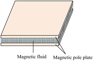
where, stands for the amount of inference results corresponding to the maximum membership degree. The FC algorithm needs to be combined with MRD to directly apply to the control of VNF of irregular building structures. Therefore, a FC system based on MRD has been proposed. MRD is to put small soft magnetic particles into the non-magnetic fluid, so that the liquid changes from Newtonian fluid to plastic solid under the action of magnetic field. In this process, the device will output the damping force of magnetorheological fluid. Because the device has a fast response speed, and can also output the damping force continuously, the device is widely used. The movement mode of magnetorheological fluid in MRD is expressed in Fig. 3 [17-19].
Fig. 3Schematic diagram of magnetorheological fluid movement
When the magnetorheological fluid is in a stable shear field, the constitutive relationship of the magnetorheological fluid can be expressed by Eq. (10):
where, refers to shear stress; represents zero field viscosity; means yield stress of magnetorheological fluid; indicates shear strain rate. When the magnetic particles in the magnetorheological fluid do not reach magnetization saturation, the theoretical yield stress of the magnetorheological fluid can be expressed by Eq. (11):
where, refers to the volume content of the particles; denotes the saturation magnetization strength of the particles; stands for the actual permeability; indicates the applied magnetic field strength. MRD can be divided into shear type dampers, valve type dampers, and shear valve type dampers. The output of shear valve type MRD can be regarded as the sum of shear type damping force and valve type damping force, which can be represented by Eq. (12):
where, means the damping force of the shear valve type MRD; denotes the apparent density of the magnetorheological fluid; indicates the effective length of the piston; expresses the piston diameter; denotes the magnetorheological fluid channel diameter; expresses the gap; means the magnetic core radius; denotes the direction of piston movement. In shear valve type MRD, the piston diameter is much larger than the gap. Therefore, the damping force of shear valve type MRD can be calculated using the calculation formula of valve type MRD, as shown in Eq. (13):
where, means the damping force of valve type MRD. According to Eq. (13), the damping force of shear valve type MRD is composed of passive viscous damping force and variable Coulomb damping force. The ratio of variable Coulomb damping force to passive viscous damping force is the adjustable multiple of MRD damping force, as calculated in Eq. (14):
From the above formula, there is a contradiction between increasing the damping force output and the adjustable multiple. Therefore, Eq. (13) can be rewritten as Eq. (15):
where, means the relative velocity of MRD; denotes the viscous damping coefficient; represents the adjustable Coulombic resistance of MRD. The vibration control of irregular building structures requires the installation of controllers between structural layers to achieve the seismic effect of the building structure. The study compared the seismic effect of FC algorithm and linear quadratic regulator (LQR) control algorithm, and the specific structure is shown in Fig. 4.
Fig. 4 shows the MRD FC system designed for the study. For the vibration of building structures, there are two main sources of excitation that need to be considered. The first is that earthquakes generate waves that propagate through the ground and exert dynamic effects on the building. Secondly, the vibration caused by traffic could come from passing vehicles, trains, or other transportation facilities. These vibrations can be transmitted to nearby buildings through the ground or other means. In this system, the horizontal and lateral degrees of freedom of the building structure are retained, while the rotational degrees of freedom of the building structure are ignored. The horizontal stiffness of the floor slab is set to infinity. At this point, only the effect of vertical earthquakes on the building structure needs to be considered to compare the seismic control effect of control algorithms on the building structure. In addition to the FC mentioned above, the control of building structural models also needs to consider decentralized control strategies [20, 21]. Therefore, a fuzzy decentralized control system is studied and designed, as shown in Fig. 5.
Fig. 4Vibration control system for irregular building structures
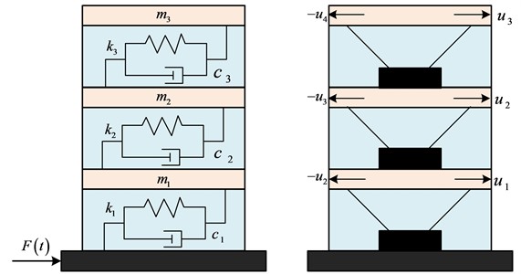
Fig. 5Architectural model and subsystem division
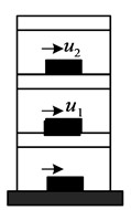
a) Building model
b) Substruction division
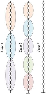
The model adopts three decentralized strategies. The first strategy divides the model into three subsystems, the second strategy divides the model into five subsystems, and the third strategy completely divides the model. Each layer is equipped with a fuzzy controller, and each layer of each decentralized strategy is equipped with an actuator to compare the control effect of the decentralized strategy. When actuators acted between floors, it will affect the working conditions of the upper and lower actuators, resulting in FC not meeting the expected requirements for displacement and acceleration control of building structures. Therefore, it is necessary to consider the control effect of MRD when used in multi-story buildings. The study supported MRD on the negative first and second floors of the building structure, allowing it to be directly supported on the ground, observing the vibration control effect of the building structure, and recording the impact of different input quantities on the control effect. At this time, the control system of the structure can be divided into open-loop control system, closed-loop control system, and open-closed-loop control system, as shown in Fig. 6.
Fig. 6Vibration control system
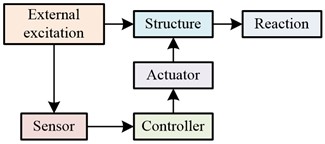
a) Open loop
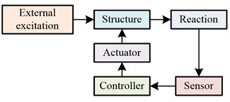
b) Closed loop
c) Open-closed loop
The control behavior of an open-loop control system is preset in advance, and the response of the structure is not considered during the control process. The output end will not have an impact on the control results of the system [22, 23]. The open-loop control system had a simple structure, low cost, but significant errors. A closed-loop control system uses sensors to obtain the response status of the structure, calculate the deviation between the actual and expected response of the structure, and adjust the structural condition based on the calculation results to make the actual response status of the structure closer to the expected result. At this time, the control system does not consider the magnitude of external forces. The open-closed-loop control system not only considers the structural response, but also needs to consider the magnitude of external forces. It utilizes the advantages of the open-loop control system to improve the closed-loop control system. To improve the control accuracy of the control system, a feedforward control structure can also be used as a feedback control supplement to the control system, forming a composite control system.
4. Analysis of simulation results
The main content of this chapter is the analysis of simulation experimental data results, which is divided into two sections. The first section is the estimation results of the VNF of irregular building, and the second section is the effectiveness analysis of the seismic control system of irregular buildings.
4.1. Estimation results of VNF of irregular building structure
The study utilized Ansys software to complete FEA modeling of irregular building structures. The structural elements of the model included longitudinal and transverse columns, beams, slabs, etc., with materials such as steel and concrete, and boundary conditions of constraints and loading. Then the experiment compared the influence of different grid division sizes on the natural frequency of building structure vibration, and the results are shown in Fig. 7.
Fig. 7(a) shows the variation trend of the longitudinal frequency (LF), transverse frequency (TF), and number of units of Model 1 with grid size. As the grid size continued to increased, the amount of cells in the FEA model continued to decrease, while the LF and TF both increased. The LF increased significantly, with a cell size of 0.85, the lowest amount of cells being 32270, the highest LF being 10.44 Hz, and the highest TF being 10.51Hz. Fig. 7(b) shows the variation trend of the LF, TF, and amount of cells of Model 2 with grid size. The data variation trend of Model 2 was similar to that of Model 1, but the LF of Model 2 was higher than the TF, which was opposite to Model 1. When the grid size was 0.85, the number of cells was the lowest, 17680, the LF was the highest, 10.31 Hz, and the TF was the highest, 9.89 Hz.
Fig. 7Trend of model data variation with grid size
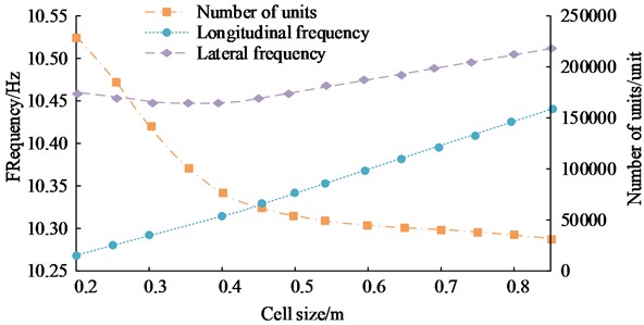
a) Model 1
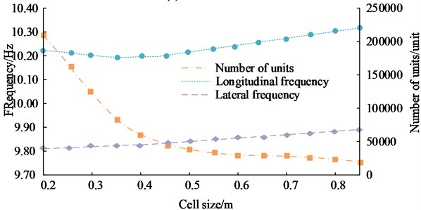
b) Model 2
4.2. Simulation results analysis of MRD FC system
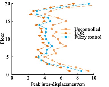
LQR is a commonly used vehicle lateral control algorithm. To verify the performance of the FC algorithm proposed in the study, the value of interlayer peak displacement (PD) response of the two algorithms under the influence of El Centro wave and Kobe wave was studied and compared. The results are expressed in Fig. 8.
Fig. 8(a) shows the comparison of the inter story PD response of two control algorithms under the influence of El Centro waves. When the building had 5 floors, the inter story PD response of both control algorithms reached the minimum, that of LQR and FC algorithm were 2.0 cm and 2.2 cm, respectively. When the building had 20 floors, the inter story PD response of both control algorithms reached the maximum. At this point, that of the LQR and fuzzy algorithm were 8.3 cm and 6.8 cm, respectively. Fig. 8(b) shows the comparison of inter story PD response between two control algorithms under the influence of Kobe waves. When the building had 17 floors, the inter story PD response of the building structure was the smallest. At this time, that of the fuzzy and LQR control algorithm were 2.3 cm and 3.6 cm, respectively. By comparing these values, when the number of building floors increased from 5 to 20, whether using LQR control algorithm or FC algorithm, the PD response between floors significantly increased. In addition to the PD response between layers, the study also compared the peak acceleration (PA) response of two algorithms under the influence of two seismic waves, as shown in Fig. 9.
Fig. 8Interstory PD response
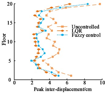
a) El Centro
b) Kobe
Fig. 9PA response
a) El Centro
b) Kobe
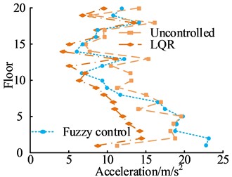
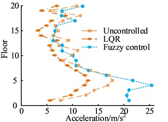
Fig. 9(a) shows the comparison of the PA response of two algorithms under the influence of El Centro waves. When the building had 11 floors, the LQR control algorithm could make the PA response lower than that of the FC algorithm. At this time, that of the LQR and FC algorithm were 6.8 m/s2 and 7.1 m/s2, respectively. Fig. 9(b) shows the comparison of the PA response of two algorithms under the influence of Kobe waves. When the building was four floors, that of the LQR control algorithm was 25 m/s2. The FC algorithm could effectively reduce the PA response of the building structure. Regardless of the amount of building floors, the PA response of the FC algorithm was always lower than that of the uncontrolled situation and the LQR control algorithm. After comparing the PD response and PA response between the two algorithms, the study also compared the control forces of the two algorithms under the influence of two seismic waves, as shown in Fig. 10.
Fig. 10Comparison of control forces between two algorithms
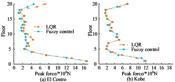
Fig. 10(a) shows the comparison of control forces between two algorithms under the influence of El Centro waves. The control forces of the two control algorithms were basically the same. The difference in control forces between the two algorithms was significant when the building had 8 floors and 20 floors. When the building had 8 floors, the control force of the fuzzy and LQR control algorithm were 5.0×10⁶ N and 3.8×10⁶ N, respectively. When the building had 20 floors, the control force of the fuzzy and LQR control algorithm were 7.8×10⁶ N and 5.1×10⁶ N, respectively. Fig. 10(b) shows the comparison of control forces between the two algorithms under the influence of Kobe waves. Regardless of the number of building floors, the control forces of the two algorithms were basically the same, with no significant difference. After determining the control effect of FC algorithm in building structures, simulation experiments were conducted on multi-layer MRD support between floors, and the results are shown in Fig. 11.
Fig. 11PD and PA response of MRD FC algorithm supported between layers
a) Displacement response peak
b) Peak acceleration response
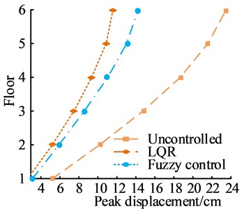
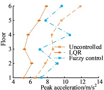
Fig. 11(a) shows the PD response. In a 6-story building structure, the difference in PD response between the two control algorithms was the largest. At this time, the PD response of the FC and LQR algorithms were 11.65 cm and 14.20 cm, respectively. Fig. 11(b) shows the PA response. The FC algorithm could effectively reduce the PA of building structures, while the LQR algorithm had poor control effect on the PA of building structures with large fluctuations. The FC algorithm could stably reduce the PA of building structures. The study also compared the PD and PA response under different control methods when MRD was supported on the ground, as shown in Fig. 12.
Fig. 12PD and PA response of different control methods supported on the ground
a) Displacement response peak
b) Peak acceleration response
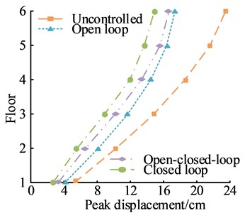
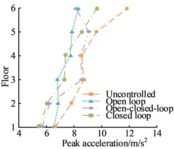
Fig. 12(a) shows a comparison of the PD response of different control methods. All three control methods could effectively reduce the PD response of the building structure, among which the closed-loop control method had the best control over the PD response. Under this control method, the PD response of the building structure was the lowest. When the building had 6 floors, the PD response of the building structure under this control method was 14.85 cm. Fig. 12(b) shows the comparison of the PA response of different control methods. The control effect of the open-loop control method was the worst. The overall difference in the control effect of the open-loop control method, i.e. the closed-loop control method, was small, and the local difference was large. All three control methods could reduce the PA response of the building structure.
5. Conclusions
To accurately estimate the fixed vibration frequency of irregular buildings and improve their seismic performance, a FEA model for calculating the fixed vibration frequency of irregular buildings was proposed, and a FC algorithm was proposed to control the vibration of irregular building structures to improve their seismic resistance. The results indicated that the FEA model could more intuitively and accurately calculate the LF and TF of irregular building structures. The LF of Model 1 was 10.44 Hz, and the TF was 10.51 Hz; the LF of Model 2 was 10.31 Hz, and the TF was 9.89 Hz. The FC algorithm had a good control effect on the displacement and acceleration of building structures. When the building had 6 floors, the PD response of the FC algorithm was 11.65 cm and the PC response was 7.9 m/s2, while the PD response of the LQR algorithm was 12.31 cm and the PC response was 8.2 m/s2. The closed-loop control method had the minimum PD. When the building had 6 floors, the PD of closed-loop control was 14.86 cm, while the PC of open-loop control method was the lowest. When the building had 6 floors, the PC of open-loop control was 8.13 m/s2. This study used FEA method to estimate the natural vibration frequency of irregular building structures, and proposed a FC algorithm to improve the seismic performance of irregular buildings. A high cost irregular building vibration control strategy has been proposed, which cannot be applied on a large scale to improve the seismic performance of irregular buildings. This can further reduce the cost of improving the seismic resistance of irregular buildings.
References
-
T. K. Karki, “What did the 2015 earthquake tell us about what the state of earthquake resilience in Kathmandu metropolitan city was?,” International Journal of Disaster Resilience in the Built Environment, Vol. 10, No. 2/3, pp. 188–202, Sep. 2019, https://doi.org/10.1108/ijdrbe-12-2018-0052
-
K. Murotani, “Large Scale Numerical Simulation Reproducing of Tsunami Behavior against a Station Building,” Quarterly Report of RTRI, Vol. 60, No. 1, pp. 58–64, Feb. 2019, https://doi.org/10.2219/rtriqr.60.1_58
-
M. M. Selim and S. A. El-Safty, “Vibrational analysis of an irregular single-walled carbon nanotube incorporating initial stress effects,” Nanotechnology Reviews, Vol. 9, No. 1, pp. 1481–1490, Dec. 2020, https://doi.org/10.1515/ntrev-2020-0114
-
C. Edlund and S. Ramakrishnan, “An analytic study of vibrational energy harvesting using piezoelectric tiles in stairways subjected to human traffic,” European Journal of Applied Mathematics, Vol. 30, No. 5, pp. 968–985, Oct. 2019, https://doi.org/10.1017/s095679251800058x
-
R. Moheimani and H. Dalir, “Static and dynamic solutions of functionally graded micro/nanobeams under external loads using non-local theory,” Vibration, Vol. 3, No. 2, pp. 51–69, Apr. 2020, https://doi.org/10.3390/vibration3020006
-
K. Singh, N. Jain, and J. Bhaskar, “Vibrational analysis of glass/carbon fiber reinforced hybrid laminate composites,” Journal of Theoretical and Applied Mechanics, Vol. 50, No. 3, pp. 259–277, Aug. 2020, https://doi.org/10.7546/jtam.50.20.03.04
-
H. Sun and S. Yuan, “Adaptive finite element analysis of free vibration of elastic membranes via element energy projection technique,” Engineering Computations, Vol. 38, No. 9, pp. 3492–3516, Sep. 2021, https://doi.org/10.1108/ec-09-2020-0511
-
J. Donadel and H. Martins Gomes, “Fuzzy heuristic control of an electrodynamic shaker in accelerated HALT/HASS tests,” Ingeniare. Revista Chilena De Ingeniería, Vol. 27, No. 1, pp. 101–112, Mar. 2019, https://doi.org/10.4067/s0718-33052019000100101
-
B. Yang, A. Zhang, Y. Bai, K. Zhang, and H. Li, “Development and simulation of magnetorheological damper for segment erector vibration control,” Transactions of the Canadian Society for Mechanical Engineering, Vol. 43, No. 2, pp. 237–247, Jun. 2019, https://doi.org/10.1139/tcsme-2018-0131
-
M. Azizi, R. G. Ejlali, S. A. Mousavi Ghasemi, and S. Talatahari, “Upgraded whale optimization algorithm for fuzzy logic based vibration control of nonlinear steel structure,” Engineering Structures, Vol. 192, No. 1, pp. 53–70, Aug. 2019, https://doi.org/10.1016/j.engstruct.2019.05.007
-
N. Jafari and M. Azhari, “Free vibration analysis of viscoelastic plates with simultaneous calculation of natural frequency and viscous damping,” Mathematics and Computers in Simulation, Vol. 185, No. 1, pp. 646–659, Jul. 2021, https://doi.org/10.1016/j.matcom.2021.01.019
-
Z. Xing, X. Wang, W. Zhao, L. Sun, and N. Niu, “Calculation method for natural frequencies of stator of permanent magnet synchronous motors based on three-dimensional elastic theory,” IEEE Transactions on Energy Conversion, Vol. 36, No. 2, pp. 755–766, Jun. 2021, https://doi.org/10.1109/tec.2020.3030042
-
D. Zhang, A. Polamarasetty, M. O. Shahid, B. Krishnaswamy, and C. Ma, “Passive mechanical vibration processor for wireless vibration sensing,” arXiv:2305.10687, 2023, https://doi.org/10.48550/arxiv.2305.10687
-
N. Acharya, “Finite element analysis on the hydrothermal pattern of radiative natural convective nanofluid flow inside a square enclosure having nonuniform heated walls,” Heat Transfer, Vol. 51, No. 1, pp. 323–354, Jan. 2022, https://doi.org/10.1002/htj.22309
-
X. Huang, B. Di, J. Wei, D. Shuai, and L. He, “Finite-element analysis of noise preceding the arrival of S-Wave in ultrasonic measurements of rock velocities,” IEEE Transactions on Ultrasonics, Ferroelectrics, and Frequency Control, Vol. 68, No. 3, pp. 742–752, Mar. 2021, https://doi.org/10.1109/tuffc.2020.3011958
-
Bustan, Hoda Moodi, and Danyal, “Adaptive interval type-2 fuzzy controller for variable-speed wind turbine,” Journal of Modern Power Systems and Clean Energy, Vol. 10, No. 2, pp. 524–530, 2022, https://doi.org/10.35833/mpce.2019.000374
-
R. Hanif, S. Mustafa, S. Iqbal, and S. Piracha, “A study of time series forecasting enrollments using fuzzy interval partitioning method,” Journal of Computational and Cognitive Engineering, Vol. 2, No. 2, pp. 143–149, Mar. 2022, https://doi.org/10.47852/bonviewjcce2202159
-
P. Devikiran, N. Puneet, A. Hegale, and H. Kumar, “Design and development of MR damper for two wheeler application and Kwok model parameters tuning for designed damper,” Proceedings of the Institution of Mechanical Engineers, Part D: Journal of Automobile Engineering, Vol. 236, No. 7, pp. 1595–1606, Jun. 2022, https://doi.org/10.1177/09544070211036317
-
K. E. Majdoub, F. Giri, and F.-Z. Chaoui, “Adaptive backstepping control design for semi-active suspension of half-vehicle with magnetorheological damper,” IEEE/CAA Journal of Automatica Sinica, Vol. 8, No. 3, pp. 582–596, Mar. 2021, https://doi.org/10.1109/jas.2020.1003521
-
K. D. Saharuddin et al., “Prediction model of magnetorheological (MR) fluid damper hysteresis loop using extreme learning machine algorithm,” Open Engineering, Vol. 11, No. 1, pp. 584–591, Jan. 2021, https://doi.org/10.1515/eng-2021-0053
-
G. Tian et al., “Studies on the thermal optical properties and solar heat gain of thin membrane structure industrial building,” Solar Energy, Vol. 213, No. 1, pp. 81–90, Jan. 2021, https://doi.org/10.1016/j.solener.2020.10.083
-
S. Wei, H. Yang, B. Gao, H. Cheng, R. Lu, and L. Dong, “Experimental research on temperature distribution and charring rate of typical components of wood structure building,” Journal of Fire Sciences, Vol. 40, No. 2, pp. 134–152, Mar. 2022, https://doi.org/10.1177/07349041211073303
About this article

The authors have not disclosed any funding.
The datasets generated during and/or analyzed during the current study are available from the corresponding author on reasonable request.
The authors declare that they have no conflict of interest.
