Abstract
In order to effectively improve the seismic and impact resistance performance of soft rock tunnels, a composite support method was proposed and validated in the paper. The UDEC (Universal Distinct Element Code) model of soft rock layers was established, and the movement and subsidence characteristics of the roof and floor of the rock layers under impact loads was simulated and calculated. As a result, a composite support scheme with good cushioning performance was proposed. The top and sides of the tunnel were supported by a combination of anchor rods of different lengths and metal mesh, reinforced by steel beams and vibration absorbing filler around. The anchor rod was designed as a segmented loading structure, and can be set to different preloading forces based on the internal deformation of the rock layer. The dynamic response testing scheme was designed, and the results indicate that the segmented loading anchor rod has a significant buffering effect on the response to impact load, and can provide reasonable tension feedback at different stages. Research has found that when the water cement ratio is 0.5-1.5, the curing efficiency and strength are both higher. In order to compare the seismic performance of composite support and traditional constant resistance anchor rod support, local blasting experiments were conducted. Based on a blasting vibration tester, a data detection and transmission system were designed to obtain the vibration speed of the tunnel roof during the vibration process. The research results show that composite support can reduce the maximum vibration by more than 40 %, stabilize the fragmentation coefficient at 1.38, and have a very significant vibration reduction effect.
Highlights
- The UDEC (Universal Distinct Element Code) model of soft rock layers was established, and the movement and subsidence characteristics of the roof and floor of the rock layers under impact loads was simulated and calculated.
- The top and sides of the tunnel were supported by a combination of anchor rods of different lengths and metal mesh, reinforced by steel beams and vibration absorbing filler around.
- anchor rod was designed as a segmented loading structure, and can be set to different preloading forces based on the internal deformation of the rock layer.
1. Introduction
As is well known, seismic resistance [1] is one of the most important indicators for judging the safety of tunnels. Generally, the geological structure of coal mine tunnel is complex. Especially, if the tunnel is composed of soft rock structures with large deformation characteristics, its seismic performance is significantly insufficient. Due to the high porosity of soft rock layers and the uneven bonding force of mixed components, the average compressive strength of the rock layers is low. Especially in humid production environments, rock mass flow is prone to occur under relatively small vibration or excitation forces [2]. Therefore, improving the support effect of large deformation tunnels has always been a technical challenge in civil engineering. In terms of support research for soft rock tunnels, representative examples are as follows: Jyant [3] proposed a surface subsidence model that evaluates the stability of tunnel support based on the ultimate collapse analysis of lower and upper bound finite element limit analysis (FELA); Zhao [4] established an interaction model between surrounding rock and flexible support system, taking into account the influence of tunnel excavation face advancement and installation delay of flexible support system, and obtained a closed form time-varying solution for displacement and stress around the tunnel; Shen [5] established an interaction model between surrounding rock and flexible support system, taking into account the influence of tunnel excavation face advancement and installation delay of flexible support system. The closed form time-varying solution of displacement and stress around the tunnel was obtained, and the maximum horizontal displacement of the lining structure occurred at the tunnel arch was verified. For large deformation surrounding rock, conventional support has certain defects, and the design and verification of tunnel comprehensive support structures are limited. However, there have been few attempts or innovations in new support methods in engineering, often increasing safety at the cost of safety factors, such as increasing the number of anchor rods too much, which is not conducive to the improvement of economic and social benefits. Therefore, the paper innovatively proposes a combined tunnel support scheme, which includes segmented pre-loaded anchor rods, fillers, hydraulic props, etc. Based on engineering practice experience and testing, its layout is reasonably set to effectively improve its seismic resistance. For the developed segmented anchor rod and optimized filling material, research is conducted through a combination of simulation analysis and experimental verification. On the premise of improving the stability of the tunnel, the production cost can be kept in a more reasonable state.
2. Dynamic characteristics of soft rock strata movement
2.1. Analysis of overlying rock collapse process
For most coal mine tunnels, the phenomenon of roof and floor layering is obvious. Among these rock layers, some have high strength and are not easily broken, such as hard rock layers such as sandstone, siltstone, and limestone. The other part of the rock formations have low strength and are prone to collapse, such as weak rock formations such as mudstone, shale, and coal. The roof of the tunnel is composed of rock layers of different strengths. If special factors such as primary fractures and faults are not considered, the roof rock collapse of the goaf has the following characteristics due to the alternating changes of strong and weak rock layers [6]. Hard rock layers have strong anti-interference ability and can form large, unbreakable suspended roofs. For soft rock tunnels, the contact or detachment between the rock layer and the underlying rock mass is weak, so the downward pressure applied is relatively small. Weak rock layers have weak anti-interference ability and may collapse after small-scale exposure. When the rock layer approaches the coal seam, it usually rises with mining, and the pressure of the collapsed rock mass is completely exerted on the underlying rock mass. Therefore, the fracture of the rock layer is controlled by the hard roof. When the hard roof panel ruptures and sinks, several weak rock layers above collapse simultaneously, which is the grouping phenomenon of rock collapse [7].
The fracture of the main roof will cause a sharp increase in pressure on the roof of the coal mining face, as the face continues to move forward. The function of the support device is to stay away from the pressure area and prepare to withstand the next roof pressure, but the collapse of the rock layer continues to develop upwards [8]. However, the continuous collapse of this high level rock layer is no longer able to have a significant impact on the working face. The gob-side entry retaining is located at the edge of the goaf and cannot avoid the disturbance load caused by the collapse of high-level rock layers. Therefore, it is necessary to expand the field of view of overlying rock activities to higher levels.
2.2. Simulation of overlying rock sinking movement
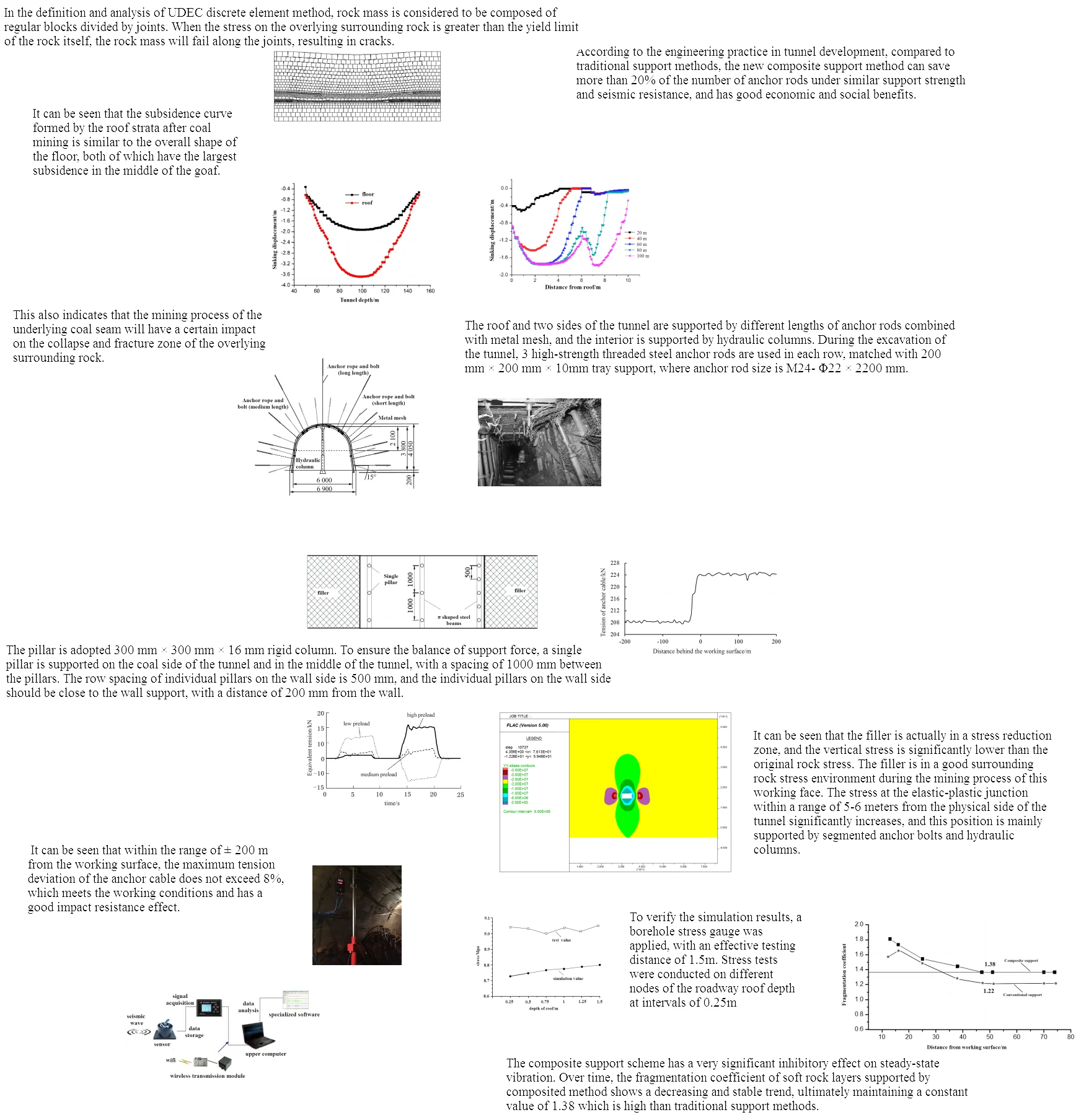
Based on the actual conditions of the mining area and the UDEC software, the dynamic characteristics of overlying rock can be studied through numerical simulation methods. This can obtain the collapse characteristics of the overlying coal seam roof and the stress distribution law of the surrounding rock of the working face after the overlying coal seam is mined. The Moore Coulomb criterion is adopted in the calculation [9], and the mechanical parameters of each rock layer in the model refer to laboratory rock testing parameters are shown in Table 1. In the definition and analysis of UDEC discrete element method, rock mass is considered to be composed of regular blocks divided by joints. When the stress on the overlying surrounding rock is greater than the yield limit of the rock itself, the rock mass will fail along the joints, resulting in cracks. According to the influence of conventional vibration disturbances during coal mine production, the external excitation pressure of the simulation model is set at 1.2 MPa. Through calculation, it can be concluded that the subsidence of the overlying strata after extraction is shown in Fig. 1. According to the simulation results of rock subsidence, it can be seen that due to the model not applying specific support results, the disturbance effect cannot be actively controlled. After coal mining, it will cause two disturbances to the overlying rock layers. The goaf not only loses stability, but also the overlying rock fractures develop rapidly. These fractures divide the overlying rock layers into separate structures, and some incompletely closed fractures weaken the transmission of force between the overlying rock layers. However, in local locations, the rock mass forms a “hinge arch” structure that supports the overlying rock layer, prevents rock failure and collapse, and temporarily maintains stability of the structure.
Table 1Mechanical parameters of coal mine rock layers
Rock strata | Bulk modulus / MPa | Shear modulus / MPa | Cohesion / MPa | Internal friction angle / degree | Density / kg·m3 |
Siltstone | 5920 | 5730 | 1.8 | 31 | 2600 |
Mudstone | 6000 | 2100 | 1.5 | 24 | 2500 |
Medium sandstone | 6500 | 2000 | 2.8 | 30 | 2700 |
Gritstone | 5500 | 1900 | 2.5 | 29 | 2650 |
Coal | 5500 | 2050 | 0.8 | 22 | 1350 |
Sandy mudstone | 6500 | 2200 | 2.4 | 28 | 2600 |
Limestone | 8400 | 2700 | 3.4 | 34 | 2760 |
Fig. 1Sinking state of rock layers
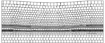
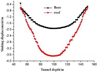
Fig. 2The variation pattern of sinking distance
a) The maximum sinking distance of the roof and floor strata
b) Roof sinking displacement at different tunnel depths
The maximum deformation distribution of the overlying strata roof and floor is shown in Fig. 2. It can be seen that the subsidence curve formed by the roof strata after coal mining is similar to the overall shape of the floor, both of which have the largest subsidence in the middle of the goaf. The subsidence curve is high in the middle and low on both sides, presenting the characteristics of a subsidence basin. From the perspective of subsidence values, the maximum subsidence of the surrounding rock of the floor reaches 1.93 m, and the maximum superimposed subsidence of the roof is 3.68 m. This also indicates that the mining process of the underlying coal seam will have a certain impact on the collapse and fracture zone of the overlying surrounding rock. However, from the perspective of the changes in the subsidence area, the impact is not significant. The superimposed impact caused by the mining is mainly concentrated above the goaf, and there is little impact towards the outer sides on both sides. It can also be seen that the settlement and movement of tunnel rock layers have obvious sudden changes, which are very detrimental to the reliability and safety of mechanical structures. Therefore, the key issue is to effectively reduce the distribution of settlement, improve the distribution of stress, and better resist external vibration through reasonable support and reinforcement.
3. Design and construction of composite seismic support structures
3.1. Overall structure and layout
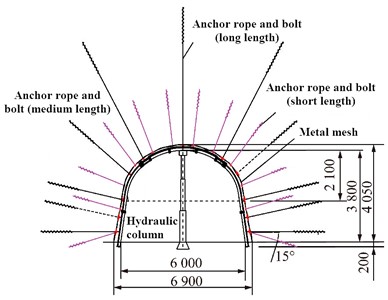
As we all know, the coal mining tunnel that studied in the paper is mainly composed of large deformed soft rock layers, and conventional support is difficult to meet seismic requirements. Therefore, a composite support form for the working face has been proposed, as shown in Fig. 3. The roof and two sides of the tunnel are supported by different lengths of anchor rods combined with metal mesh, and the interior is supported by hydraulic columns. During the excavation of the tunnel, 3 high-strength threaded steel anchor rods are used in each row, matched with 200 mm × 200 mm × 10 mm tray support, where anchor rod size is M24- Φ22 × 2200 mm. Each anchor rod is extended and anchored with Z2335 and Z2360 resin coil. The number of anchor rods required depends on multiple factors, such as geological conditions, construction methods, load levels, etc. Based on engineering experience and rock characteristics, it can be determined that 300-400 anchor rods should be installed within every 1000 square meters. Therefore, the spacing between anchor rods is set as 2000 mm, and the row spacing is set as 1500 mm. The pre tightening force of the anchor rod shall not be less than 80 kN, and the pre tightening torque shall not be less than 300 N·m. The anchor cables in the middle of the tunnel are staggered with the anchor rods on the wall side, with a row spacing of 2000 mm and a column spacing of 3000 mm. The reinforced support should be constructed 200 meters in front of the working face.
Fig. 3Composite support scheme form for working face
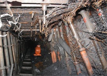
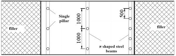
Within the range of 35 meters in front of the working face to 200 meters behind the working face, individual hydraulic support is used to assist in relieving mining pressure on the tunnel. The auxiliary support of the tunnel adopts the form of single pillars combined with hinged top beams or π shaped steel beams, as shown in Fig. 4. The pillar is adopted 300 mm × 300 mm × 16 mm rigid column. To ensure the balance of support force, a single pillar is supported on the coal side of the tunnel and in the middle of the tunnel, with a spacing of 1000 mm between the pillars. The row spacing of individual pillars on the wall side is 500 mm, and the individual pillars on the wall side should be close to the wall support, with a distance of 200 mm from the wall. The spacing between pillars can be adjusted appropriately according to the width of the tunnel, but it should be ensured that the spacing between pillars is not greater than 1000 mm. Taking 1000 m2 as the estimated area, the cost of using traditional composite support is approximately 120 euros/m2, which can reduce the cost by about 10 % compared to traditional support.
Fig. 4Internal support and reinforcement scheme
3.2. Design of reinforced anchor support
The softening of tunnel rock layers is a common problem during coal mining. As tunnel construction progresses, some highly stable surrounding rocks will expand and transform into soft rock structures under the action of air, water vapor, and other factors. These sudden changes in rock structure can easily lead to high stress concentration in the tunnel [10]. This is also an important reason for the damage or even fracture of traditional steel anchor rods when the rock properties change. It can be seen that directly using rigid support cannot meet the reinforcement requirements of soft rock. It is necessary to fully consider the release of energy to avoid sudden displacement [11]. To solve this problem, a composite anchor rod with a multi-level structure was designed. From a structural analysis, it is composed of three parts of anchor rods with the same diameter connected in series, each part can independently complete the support, and different preloads can be set according to the internal pressure of the rock layer, as shown in Fig.5. To improve the corrosion resistance of the anchor rod, the axial structure of the anchor rod is set to be made of polymer nylon material. At the end of the anchor rod, the supporting anchor cable is equipped with an enhanced corrugated guide groove mechanism to achieve pressure unloading, which can avoid the impact fracture of the anchor rod. This type of anchor rod has the effect of grouting reinforcement. The optimized slurry can be injected under high pressure through the rubber hose in the center. Under the conditions of segmented preloading and constant resistance deformation, there will be no sudden problems with the deformation of the surrounding rock. In parameter design, the deformation range is required to be greater than the ultimate displacement of the surrounding rock, so that the entire support process is in a balanced state. According to testing, the constant resistance device inside the anchor rod has a good flexibility effect, which can ensure that the contact resistance remains stable at 200-400 kN and the maximum extension is not less than 1.1 m.
Compared to the pressure inside the rock layer, the preload of the anchor rod has a reverse effect, which stores a quantitative amount of elastic potential energy. With the operation of tunnel engineering, the surrounding rock structure undergoes changes, especially under vibration and impact loads, the elastic potential energy will gradually offset the gravitational potential energy of the rock layer. In order to adapt to the trend of dynamic load changes inside the anchor rod, specific design and construction processes were studied as follows to more effectively reduce sudden collapse problems.
Fig. 5Structural composition of anchor rods

a) Segmentation of prestress
b) Component installation diagram
(1) Before installing preloaded anchor bolts and implementing grouting reinforcement, separate hydraulic columns must be arranged in the tunnel to prevent sudden changes in internal stress in the surrounding rock during the drilling process. Based on the historical maximum vibration data of the tunnel and the distribution characteristics of rock internal pressure, the installation aperture is set at a diameter of 75 mm, with an axial expansion of 0.5 m, and the segmented preloads of the anchor bolts are 20 t, 15 t, and 10 t, respectively. Due to the hole depth being greater than the length of the anchor rod, adding fixing agent at the end needs to be maintained for more than 10 hours, otherwise it may cause loosening and reduce the grouting effect. To ensure the safety of anchor rod installation, it is necessary to monitor the pressure during drilling and installation. If the pressure and deformation of the surrounding rock exceed the limit, it is necessary to increase the number of anchor rods and add long sized anchor rods in the center of the tunnel. If construction needs to be suspended, the number of supports should be increased and supports should be installed on the excavation surface as much as possible.
Fig. 6The maximum tension of anchor cables
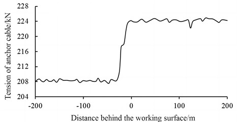
(2) In order to balance the binding force between anchor rods, it is necessary to add connectors between different anchor rods. Under normal surrounding rock pressure conditions, the spacing between each set of anchor cable components is set at 2 m. Otherwise, the spacing will be changed to 1.5 m. The connectors are generally made of strip steel, which has good stiffness, strength, and hardness. When severe vibration occurs in the tunnel, the constant resistance device inside the anchor cable structure will undergo coordinated movement to counteract the resistance constraints caused by dynamic loads. Under the action of connectors, the stability of anchor rod support is significantly enhanced. The position of pressure monitoring points is prioritized to be equidistant and set at 20 m. Through continuous monitoring, the maximum tension variation of anchor cables at different positions can be obtained as shown in Fig. 6. It can be seen that within the range of ±200 m from the working surface, the maximum tension deviation of the anchor cable does not exceed 8 %, which meets the working conditions and has a good impact resistance effect. Due to the fact that anchor cables close to the working face are more susceptible to impact loads, the primary support of anchor rods should be installed as soon as possible to prevent significant changes in the surrounding rock structure. After grouting for a period of time, the bonding force of the rock layer gradually stabilizes, and at this time, a second support can be carried out, which is the auxiliary support of the short anchor rod. According to engineering experience, the time for the second support should not be too short, usually requiring an interval of 60 days, which can balance engineering efficiency and quality.
3.3. Vibration impact test of segmental preloading support
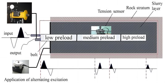
There are many potential impact load factors in coal mine tunnels, such as earthquakes, rock fracture [9], explosive impact, etc. The mechanical properties of anchor rods need to be verified, especially their response characteristics under impact loads, which is also an important basis for determining the support capacity of the rock layers inside the tunnel. In order to verify the response ability of segmented preloaded anchor rods to continuously changing impact loads [16], a dynamic response testing scheme was designed, as shown in Fig. 7. Surrounding rock model that simulated tunnel structure was prepared as 1.8 m × 0.6 m × 0.6 m, with a concrete slurry layer inside and a soft rock layer outside. The tension sensor is also arranged in a segmented manner, detecting the response of three parts of the preload separately. To simulate the true condition, the external excitation force is applied at the end of the anchor rod.
Fig. 7Experimental principle of support response to impact
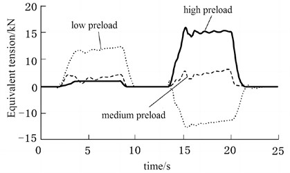
In order to determine the impact of preload on impact load response more clearly, before applying excitation force, a tension sensor is first set up to zero the tension of each segment. Through testing, the variation pattern of the equivalent tension of the anchor rod in different pre tightening stages within a single load cycle can be obtained as shown in Fig. 8. It can be seen that although the response of the anchor rod to alternating loads varies significantly in different pre tightening stages. Under preloading, the sensitivity of anchor rods between different segments to load is relatively high, and the initial response time does not exceed 1.5 seconds. The low preload area is the primary location for initial energy cancellation, therefore the feedback on the excitation force exhibits periodicity. The tension of the anchor rod in the middle area fluctuates only within a small range, and is least affected by the impact load. The response time in the high preload area is the latest, which is also a key guarantee for ensuring severe impact and large deformation. Although the excitation force has the characteristic of orthogonal transformation, the overall tension change of the anchor rod is relatively small regardless of whether the external load and the pre load direction of the anchor rod are the same or opposite. It can be inferred that this support method can effectively reduce sudden displacement caused by severe vibration and improve seismic performance.
3.4. Design of grouting materials
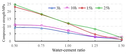
Due to the relatively high humidity of large deformation soft rock layers, the viscosity will undergo significant changes after being affected by flowing water [12]. Therefore, the grouting of anchor rods needs to focus on solving the problems of grout leakage and string grouting [13]. Considering both performance and cost, it is proposed to add a specific proportion of water glass in silicate slurry, which is very beneficial for the bonding of soft rock layers and an effective means to improve the mechanical properties of rock layers. Through experiments, it was found that the optimal water glass ratio of the grouting material for the anchor rod is 40 %, which can significantly improve the bonding force of the slurry. The initial setting time, stone content, and compressive strength under different water cement ratios are shown in Fig. 9 and Fig. 10, respectively.
Fig. 8The variation law of equivalent tension under impact load
According to the research on the slurry ratio, it is known that the water cement ratio is a key factor affecting the solidification period, petrochemical rate, and compressive strength of soft rock layers. For example, in soft rock layers with high wading capacity, a good water cement ratio can accelerate the solidification of the slurry, reduce the solidification cycle, and thus reduce the impact of water wet environment on strength. The improvement of petrochemical efficiency is also the key to ensuring the stability and constant resistance performance of anchor cables, which is significantly helpful for the seismic performance of tunnels.
Fig. 9Changes in initial setting time and stone formation rate under different water cement ratios
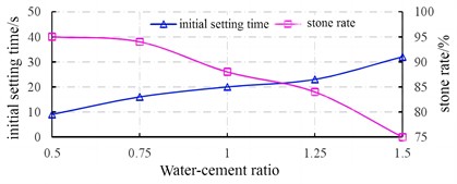
Fig. 10Changes in compressive strength under different water cement ratios
3.5. Stress analysis of filler under impact load
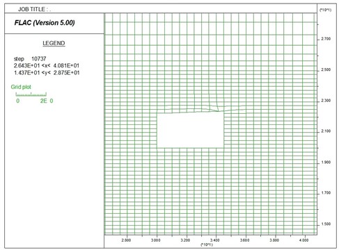
In order to study the effect of improved fillers on the seismic and impact resistance of tunnels, a corresponding numerical mechanical model was established based on the production geological conditions of the working face, as shown in Fig. 11. The thickness of the rock layer was set to 1.9 m, and the rock layer within a range of 10 m on both sides of the tunnel mesh was divided into 1.0 m×0.25 m. The mesh of roof, floor and filler was divided into 0.5 m×0.25 m. The boundary load on the calculation model is based on a mining depth of 800 m, with the bottom boundary fixed in the vertical and horizontal directions. To ensure the convergence of large deformation calculations, the mesh is set to an adaptive type. Under a transient impact load of 1.2 MPa, the stress distribution under different fillers will be simulated and calculated.
Fig. 11Analysis model of tunnel stress
When soft rock tunnels are subjected to impact loads, the surrounding rock will appear significant deformation, so a strain softening model is chosen in the simulation of filler. The stability of the tunnel is mainly related to the strength and width of the filler. Through comparative analysis of the filling material ratio in laboratory, the optimal ratio of filler is determined as shown in Table 2.
Table 2The optimal ratio of filler
Mix ratio (water, cement, coal, gangue) | Percentage of cement by volume | Compressive strength / MPa | Width of filler / m |
0.33:1:2:2 | 10.80 % | 4.8 | 1.5 |
Fig. 12Analysis results of tunnel stress
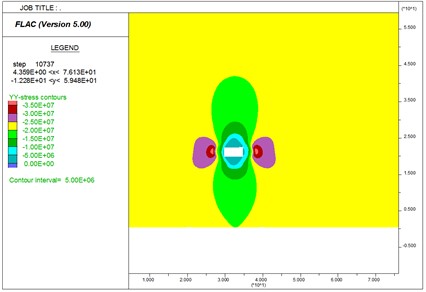
The stress distribution of the tunnel under impact force under the action of the filler is shown in Fig. 12. It can be seen that the filler is actually in a stress reduction zone, and the vertical stress is significantly lower than the original rock stress. The filler is in a good surrounding rock stress environment during the mining process of this working face. The stress at the elastic-plastic junction within a range of 5-6 meters from the physical side of the tunnel significantly increases, and this position is mainly supported by segmented anchor bolts and hydraulic columns. Although the roof experiences stress concentration along the elastic-plastic boundary of the entity under huge impact loads, the filling body can ensure that it is always in the stress reduction zone, avoiding the possibility of local surrounding rock being crushed and destroyed. It can be inferred that during the mining process of the tunnel, even if there is severe vibration, there will not be any roof cutting along the inner side of the tunnel. To verify the simulation results, a borehole stress gauge was applied, as shown in Fig. 13(a), with an effective testing distance of 1.5 m. Stress tests were conducted on different nodes of the roadway roof depth at intervals of 0.25 m, and the results are shown in Fig. 13(b). It can be seen that the filling material has a good effect on maintaining stress balance, and the maximum deviation between the test value and the simulation value is less than 5 %.
Fig. 13Verification of simulation results
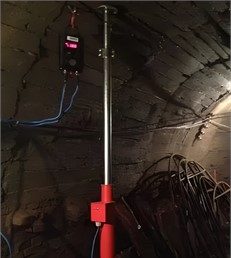
a) Installation of drilling type stress gauge
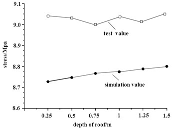
b) Comparison of stress at different measuring points
4. Test of seismic performance of supported tunnels
4.1. Design of blasting vibration test
In order to simulate the impact caused by earthquakes or collapses, local blasting is used to verify the composite support effect of the tunnel. In on-site monitoring, the blasting vibration test instrument of Blastmate III (as shown in Fig. 14(a)) is used for vibration monitoring to obtain the three-dimensional vibration velocity of the roof movement during the blasting process. Sensors convert blasting signals into digital form for storage [12], and then use computers for data processing to obtain parameters such as waveform and spectrum, as shown in Fig. 14(b). The vibration monitoring instrument has the advantages of accurate monitoring and convenient use [13].
Fig. 14Design of blasting vibration test
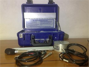
a) Blasting vibration test instrument
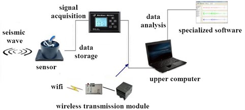
b) The principle of collecting vibration signals
According to the actual construction situation, the monitoring of blasting vibration in the middle section of the tunnel has been implemented, and data from multiple explosions has been collected. On both sides of the blasting center, composite support and traditional constant resistance anchor rod support are respectively installed to study the degree of rock protection of the two support methods under blasting disturbance. The monitoring points shall be arranged according to the following basic principles:
(1) Try to ensure that monitoring points are arranged in areas severely affected by blasting.
(2) Taking into account the characteristics of the existing tunnel site and ensuring monitoring effectiveness, monitoring points will be arranged in adjacent rock drilling chambers not far from the blasting site. At the same time, as the blasting vibration becomes stronger as it is closer to the blasting source, monitoring points will be arranged as close as possible to the blasting source while ensuring safety.
(3) Due to factors such as harsh environmental conditions, high risk factors, and insufficient manpower at the blasting site, while ensuring monitoring accuracy, monitoring points should be minimized as much as possible.
4.2. Vibration response analysis of tunnel roof
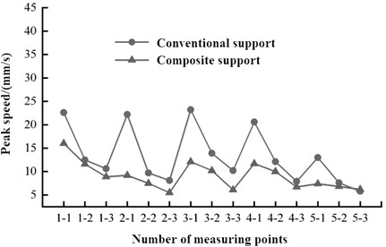
On both sides of the blasting (vibration source) center, 15 vibration velocity monitoring points were arranged in the same depth direction, all along the axial direction. The time-domain response results of the measurement points at the center of the tunnel are shown in Fig. 15. It can be seen that composite support can effectively reduce the amplitude of the roof surrounding rock, while having little impact on the natural frequency of the tunnel. In blasting testing, due to the varying time of peak values of vibration waves in different directions, the vector amplitude of wave velocity, i.e. the superposition result, is used to distinguish the vibration response. Statistical processing was conducted on the data obtained from the monitoring of various blasting vibration points. Under each support method condition, 15 sets of vibration response results with velocity as the maximum amplitude were obtained, as shown in Fig. 16. It can be seen that composite support can reduce the maximum vibration by more than 40 %, and the vibration reduction effect is very obvious.
Fig. 15Time domain characteristics of vibration response
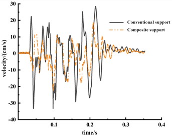
Fig. 16Vibration amplitude at different measuring points
4.3. Test of rock fragmentation and swelling
The coefficient of fragmentation and coefficient of expansion are important indicators for measuring the steady-state seismic resistance of tunnels, and are also one of the key criteria for determining the safety and stability of composite support. Essentially, the fragmentation coefficient represents the ratio of the volume of soft rock layers to their initial volume after slow long-term vibration. It can be used to predict the probability of occurrence of overlying rock fractures, separation, and collapse under severe vibration. Regarding the construction process and rock mechanics characteristics of composite support, the following steps are used to test the fragmentation coefficient and expansion.
(1) By moving the single column hydraulic support, the roof of the goaf will collapse to a stable state on its own, thus obtaining the starting height measured on the side of the tunnel.
(2) To ensure the reliability of the test results, the collapse height should be tested every 4 hours and the continuous measurement period should not be less than 2 days. If it is found that the deviation from the previous measurement result is less than 10 mm, record the measurement height at this time and use it as a stable height .
(3) Install the single column support again, drill the top plate, and determine the thickness of the soft rock layer , then the stable fragmentation coefficient can be expressed as:
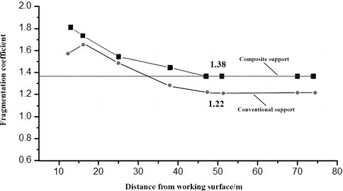
According to the steady-state measurement results under composite support conditions, the variation curve of the fragmentation coefficient with the advancement of the working face can be obtained, as shown in Fig. 17. It can be seen that the composite support scheme has a very significant inhibitory effect on steady-state vibration. Over time, the fragmentation coefficient of soft rock layers supported by composited method shows a decreasing and stable trend, ultimately maintaining a constant value of 1.38 which is high than traditional support methods. During the entire monitoring process, the fragmentation coefficient did not suddenly change, indicating that the composite support method has good reliability in the steady-state seismic reinforcement of soft rock layers.
Fig. 17Variation law of fragmentation coefficient and expansion
5. Conclusions
The seismic performance of tunnels is an important prerequisite for ensuring safe production, therefore, there are strict requirements for support effectiveness, but more difficulties in supporting soft rock layers. A composite support scheme is proposed in the paper, which has good cushioning and vibration absorption capabilities and is suitable for large deformation soft rock tunnels. Through construction design and engineering testing, the following conclusions can be drawn:
1) The composite support method belongs to a new type of roadway reinforcement method, which was innovatively designed and verified in the paper, effectively alleviating the seismic problem of large deformation surrounding rock. The soft rock structure in the tunnel is very unstable and prone to significant deformation and stress concentration during the mining process. In addition, the expanding rock layer can also cause excessive displacement of the roof, which can easily exceed the tensile limit that conventional anchor rods can withstand under the excitation force, making it difficult to achieve force balance and stable deformation. However, segmented preloaded anchor rods can effectively consider the release of energy, avoid sudden roof displacement, and alleviate the destructive force of impact loads, thereby improving the seismic resistance of the tunnel structurally.
2) In order to ensure the cushioning capacity of the segmented preloaded anchor rod, it is necessary to configure a reasonable slurry to ensure the curing effect. If the humidity of the rock layer is high, a smaller water cement ratio should be selected to obtain a higher stone rate and compressive strength. Generally, the surrounding rock can achieve good stability after 15 hours. The optimized filler can effectively reduce stress concentration and achieve good vibration absorption effect. According to the engineering practice in tunnel development, compared to traditional support methods, the new composite support method can save more than 20 % of the number of anchor rods under similar support strength and seismic resistance, and has good economic and social benefits.
References
-
A. Naserpour, M. Fathi, and R. P. Dhakal, “Demountable shear wall with rocking boundary columns for precast concrete buildings in high seismic regions,” Structures, Vol. 41, pp. 1454–1474, Jul. 2022, https://doi.org/10.1016/j.istruc.2022.05.083
-
M. A. Santos-Santiago, S. E. Ruiz, and F. Valenzuela-Beltrán, “Influence of higher modes of vibration on the seismic response of buildings with linear and nonlinear viscous dampers,” Journal of Earthquake Engineering, Vol. 26, No. 8, pp. 3914–3937, Jun. 2022, https://doi.org/10.1080/13632469.2020.1822223
-
J. Kumar and H. Jain, “Elasto-plastic ground settlement response and stability of single and twin circular unsupported and supported tunnels,” Transportation Geotechnics, Vol. 30, No. 1, p. 100620, Sep. 2021, https://doi.org/10.1016/j.trgeo.2021.100620
-
N. Zhao, Z. Shao, X. Chen, B. Yuan, and K. Wu, “Prediction of mechanical response of “a flexible support system” supported tunnel in viscoelastic geomaterials,” Archives of Civil and Mechanical Engineering, Vol. 22, No. 4, pp. 1–21, Jul. 2022, https://doi.org/10.1007/s43452-022-00485-7
-
G. Shen, Y. Lou, J. Wu, X. Jin, and Y. Xue, “Simulation analysis on seismic dynamic response of pile supported tunnels in deep backfill area of soil-rock mixture,” Vibroengineering Procedia, Vol. 46, No. 1, pp. 33–40, Nov. 2022, https://doi.org/10.21595/vp.2022.22712
-
J. M. Jara, C. García-Calzada, B. A. Olmos, and G. Martínez, “Seismic response and reliability index of rc weak story buildings on soft soils of Mexico city,” Journal of Building Engineering, Vol. 50, No. 2, p. 104199, Jun. 2022, https://doi.org/10.1016/j.jobe.2022.104199
-
I. Hafner, D. Lazarević, T. Kišiček, and M. Stepinac, “Post-earthquake assessment of a historical masonry building after the Zagreb earthquake – case study,” Buildings, Vol. 12, No. 3, p. 323, Mar. 2022, https://doi.org/10.3390/buildings12030323
-
M. El Hoseny, J. Ma, and M. Josephine, “Effect of embedded basement stories on seismic response of low-rise building frames considering SSI via small shaking table tests,” Sustainability, Vol. 14, No. 3, p. 1275, Jan. 2022, https://doi.org/10.3390/su14031275
-
Q. Xu, Y. Liu, and Y. X. Song, “Calculation method based on Loess surrounding rock loose circle theory,” (in Chinese), Science, Technology and Engineering, Vol. 21, pp. 10054–10060, 2021.
-
A. M. Svalov, “Stress concentration in wellbore zones at underground gas storages,” Journal of Mining Science, Vol. 59, No. 2, pp. 183–190, Apr. 2023, https://doi.org/10.1134/s1062739123020011
-
K. Yang, Q. Yan, Z. Shi, C. Zhang, and S. Ma, “Numerical study on the mechanical behavior of shotcrete lining with yielding support in large deformation tunnel,” Rock Mechanics and Rock Engineering, Vol. 56, No. 2, pp. 1563–1584, Feb. 2023, https://doi.org/10.1007/s00603-022-03126-w
-
L. J. Lan and C. T. Liu, “Research on real-time flutter compensation of CNC machine tools based on embedded sensor device,” (in Chinese), Machine Tools and Hydraulics, Vol. 50, No. 13, pp. 37–41, 2022.
-
R. Di Lorenzo et al., “Recommendations for motion correction of infant Fnirs data applicable to multiple data sets and acquisition systems,” NeuroImage, Vol. 200, No. 3, pp. 511–527, Oct. 2019, https://doi.org/10.1016/j.neuroimage.2019.06.056
About this article

The paper was supported by a provincial key research and development project (2023YFG10600).
The datasets generated during and/or analyzed during the current study are available from the corresponding author on reasonable request.
The authors declare that they have no conflict of interest.
