Abstract
The dynamic stability of large deformation roadway can be significantly affected by seismic vibration. In order to improve the support effect, a segmented constant resistance anchor bolt structure is proposed. The preload can be set in segments to effectively reduce the tension deviation. The support stability of this type of bolt is verified by field test and experimental simulation. Based on the bearing and deformation characteristics of surrounding rock, the supporting and installation, grouting process and anchor cable stress monitoring of this type anchor bolt are designed. Through the field measurement of the roadway, the variation laws of the rock swelling coefficient, anchor cable tension and roof subsidence under the condition of bolt support are obtained. A tunnel dynamic deformation test-bed is built to study the dynamic vibration response of the designed anchor bolt to alternating load. Applying orthogonal exciting force, the tension changes in different constant resistance sections are obtained. The results show that this type of bolt has remarkable effect of resisting alternating load, and the maximum tension deviation within ±200 m working face is less than 8 %, which has better support stability than conventional bolt.
Highlights
- In order to improve the support effect, a segmented constant resistance anchor bolt structure is proposed.
- Based on the bearing and deformation characteristics of surrounding rock, the supporting and installation, grouting process and anchor cable stress monitoring of this type anchor bolt are designed.
- A tunnel dynamic deformation test-bed is built to study the dynamic vibration response of the designed anchor bolt to alternating load.
1. Introduction
The geological structures of most roadways are complex, and their differences in rock stratum are obvious. For soft rock roadway, small seismic vibration [1] can significantly damage the structure of surrounding rock. At present, how to improve the stability of large deformation roadway [2] support has always been a technical problem in civil engineering. Due to the large porosity of the soft rock stratum, which contains more mixtures of expansive clay, kaolinite, illite and montmorillonite, the average compressive strength of the rock stratum is low and the rock mass flow is easy to occur [3]. The self-stabilization period [4] of common large deformation roadway is relatively short. Generally, the caving time is less than 12 h, the loosening radius is greater than 1.5 m, and the deformation rate is random and difficult to estimate. Under the action of peripheral pressure, the offset of roadway can exceed 1m within half a year, which makes it difficult for conventional anchor bolts to meet the support requirements.
At present, the main material of anchor bolt is mainly carbon steel, which has good unloading ability to deal with sudden load, but its adaptability to transverse load and alternating load is relatively poor, which is prone to local pressure overload and stress concentration. In order to effectively improve the support effect in large deformation surrounding rock, an anchor bolt based on glass fiber reinforced nylon is proposed in this paper, which has constant resistance performance. Different preloads can be set in sections to effectively reduce the tension deviation. In addition, through the optimization of slurry ratio, the stone rate [5, 6] and rock stratum compressive strength [7] are improved, as well as the stress distribution. Based on the field measured data, the support effect of this type of bolt is verified. In addition, the quality of glass fiber reinforced nylon bolt is smaller than that of steel bolt, the production and transportation cost is easy to control, and the economic benefit is remarkable.
2. Design of multistage prestressed support scheme
2.1. Failure principle of conventional bolt support
Compared with conventional rock stratum, the support of soft rock roadway with large deformation is more difficult, and ground pressure vibration is more likely to happen. The soft rock stratum is highly sensitive to external force factors such as water flow and vibration. Due to the large composition of mixed mudstone, there will also be a certain crushing problem under low unidirectional pressure load [8], so that the high-strength bolt cannot play its supporting role. There are three kinds of pressure on the roadway with large deformation in soft rock: loosening pressure, deformation pressure and expansion pressure. The loosening pressure is the main factor of local surrounding rock collapse, and its balanced force system is the support force of single column support and anchor cable tension. Although deformation pressure is the main source of potential energy of surrounding rock, glass fiber reinforced nylon structure can effectively buffer deformation pressure, fully release energy and make it show good controllability. Expansion pressure is a special deformation pressure, which is greatly affected by water wet environment and sudden load, and has some uncertainty.
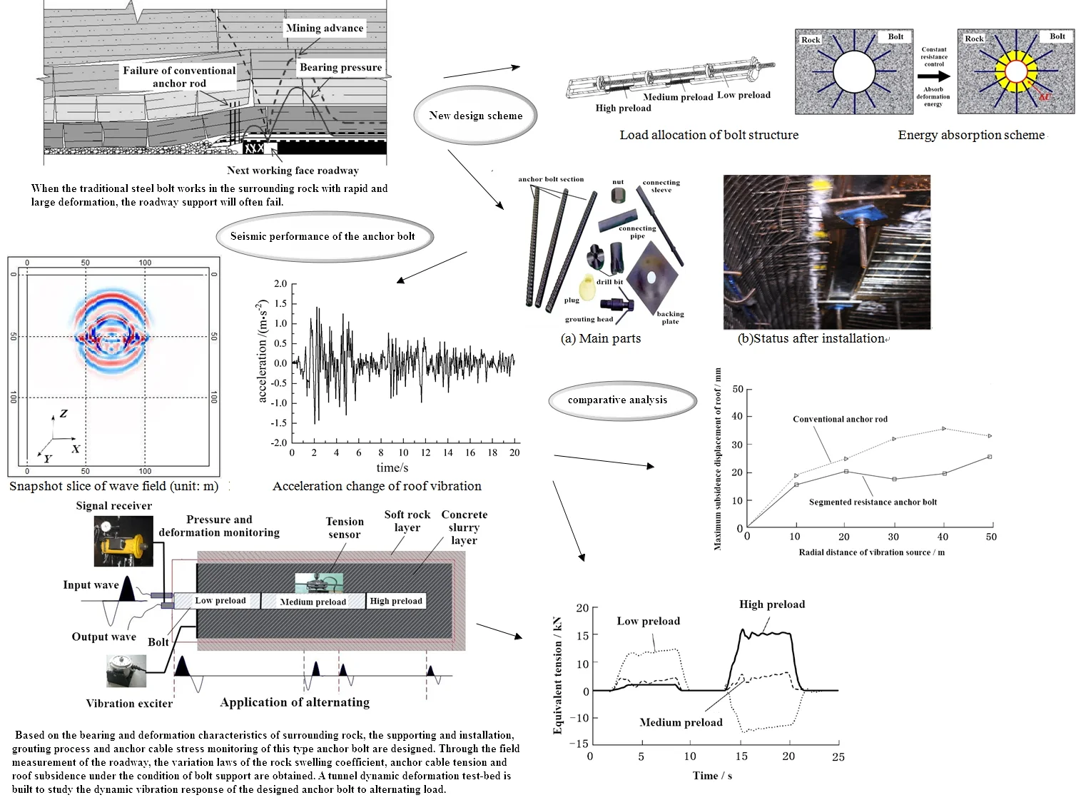
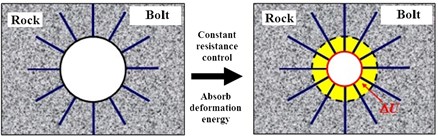
In actual coal mining, with the increase of excavation depth, some high stability surrounding rocks will swell and change into soft rock structure, showing a high degree of stress concentration. Therefore, when the traditional steel bolt works in the surrounding rock with rapid and large deformation, the roadway support will often fail. As shown in Fig. 1, during roadway construction, the sudden change of mining advance pressure and bearing pressure brings obvious dynamic disturbance to the soft rock stratum, resulting in a sharp increase in the loosening pressure and deformation pressure of the soft rock stratum, and the expanded rock stratum will cause excessive roof displacement, exceeding the tensile limit that the carbon steel bolt can bear, so it is difficult to achieve force system balance and stable deformation. It can be seen that the direct use of rigid support cannot reinforce the soft rock, and the release of energy needs to be fully considered [9] to avoid sudden roof displacement.
Fig. 1Failure principle of conventional anchor bolt
2.2. Design of segmented constant resistance anchorbolt
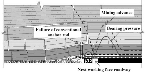
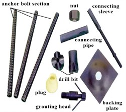
Aiming at the limit deformation and deformation rate of soft surrounding rock, a multi-level structure is proposed in this paper, which is composed of three parts connected in series, and different preloads can be set respectively, as shown in Fig. 2. The main structure of each section of anchor bolt is made of glass fiber reinforced nylon, and is equipped with anti-breaking constant resistance device and spherical guide groove thread. The center is a grouting rubber pipe with hole, and the outer edge is a torsional spiral structure. The deformation of surrounding rock can synchronously drive the deformation of rheostat, and the range of deformation is greater than the limit displacement of surrounding rock, so that the whole support process is in equilibrium. At the same time, the glass fiber reinforced nylon bolt can solve the problems that the steel bolt in the prior art cannot adapt to the uncertain displacement of rock stratum in a large range and the insufficient control of alternating stress.
The anchor cable matched with the anchor bolt is also made of glass fiber reinforced nylon, which is a tray nut structure and is provided with an annular long strip pit, as shown in Fig. 3. The nut is connected with the main structure of the bolt through spherical thread, which can not only effectively release the deformation energy of surrounding rock, but also improve the tensile strength of the bolt. In actual support, the constant resistance device in the anchor bolt can ensure that the contact resistance is maintained at 200-400 kN and the maximum extension is more than 1.1 m.
Fig. 2Load allocation of bolt structure
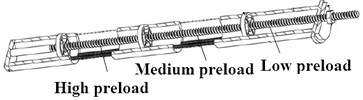
Fig. 3Energy absorption scheme
2.3. Anchor bolt construction process
Compared with the ordinary steel bolt, the modified glass fiber reinforced nylon bolt has greater elongation [10], which can effectively adapt to the impact of rock failure and energy release. Due to the large load resistance of the anchor in the initial stage, with the increase of roof displacement, the anchor with prestressed characteristics will release elastic potential energy, which can offset the deformation energy of soft rock to a certain extent, thus greatly reducing the probability of roof fall or collapse. Therefore, the anchor should meet the potential energy requirements during construction. According to the structure and performance characteristics of this type of anchor bolt, the design and construction steps are as follows.
(1) Support installation. When the roadway excavation is completed, the original stable rock stratum will undergo adaptive transformation of structure. In order to avoid large-scale plastic deformation and unidirectional tension of soft rock, the single column hydraulic prop should be installed first, and then the drilling (diameter 75 mm, axial reaming 0.5 m) and prestressed loading of the windlass should be carried out according to the ground pressure test results and construction standards, as shown in Fig. 4. As a tension element penetrating into the rock stratum, the whole bolt is divided into free section and anchor section. The free section refers to the area where the tension at the anchor head is transmitted to the anchor body, and its function is to apply prestress to the anchor. The anchorage section refers to the area where the cement paste binds the prestressed reinforcement to the soil layer. Its function is to increase the bonding friction between the anchor and the soil layer and increase the bearing capacity of the anchor. Anchoring agent [11] shall be added to the reserved position at the tail of glass fiber reinforced nylon anchor bolt. After 10h, the prestress of the each rheostat shall be adjusted to 20 t, 15 t and 10 t respectively, and then the drilling device shall be removed. During the installation of glass fiber reinforced nylon bolt, the change of surrounding rock shall be monitored in real time to ensure that there will be no large deformation of surrounding rock, otherwise the due support effect will be lost. If large deformation is found in the area near the installed anchor bolt, the number and effective length of anchor bolt shall be increased (greater than 1.5 times of the original length). When the support installation needs to be suspended, the support shall be directly against the excavation surface in advance.
(2) Bolt grouting. Grouting is one of the key technologies of glass fiber reinforced nylon bolt roadway construction. Because the fluidity, flow rate and balance of slurry have an important impact on the mechanical properties of soft rock, high-speed mixing machine and controllable booster pump can be comprehensively used to adjust the grouting parameters. According to the structural characteristics of the anchor bolt, a higher discharge volume is preset, so that the allowable pressure of the anchor bolt inner hole is not less than 1.5 times the maximum grouting pressure. Therefore, the grouting inner sleeve of anchor bolt adopts high-quality pressure resistant rubber pipe. In addition, the grouting pressure is adjusted by a controllable booster pump to maintain the pressure at ±20 % of the expected value.
Fig. 4Installation diagram of anchor bolt assembly
a) Main parts
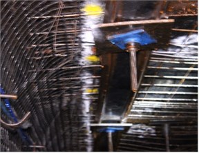
b) Status after installation
(3) Stress monitoring. According to the installation process of anchor bolt, the spacing of each set of assembly is 2 m, and each three groups are connected with strip steel, which can effectively prevent loosening displacement. The layout scheme of design stress monitoring is shown in Fig. 5. The density of monitoring points at the cutting position is 20 per meter, and the central position is 50 per meter. When the soft rock stratum has large deformation, because the denaturation energy is lower than the potential energy of the rheostat, the load in the axial direction will always be less than the internal resistance of the rheostat. Otherwise, the support stability will not be maintained.
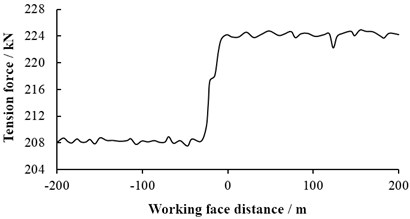
The variation law of maximum tension of anchor bolt with different lag working face distance is shown in Fig. 6. It can be seen that within the working face distance of ±200 m, the maximum tension deviation of anchor bolt is 7.8 %, and the extension effect of load is remarkable; The tension near the working face shows relatively large fluctuation, so the primary support of anchor bolt should be installed as soon as possible, and the secondary support needs to be completed after the surrounding rock is self-stabilized. Because the bolt has the characteristics of preload, it can not only improve the compressive strength of soft rock, but also improve the shear strength. According to the law of roof subsidence, the primary rigid support is difficult to meet the long-term self-stability, so the secondary support is needed. According to the test, the secondary support shows a better reinforcement effect lasting 60 days after the primary support.
Fig. 5Distribution of stress monitoring points
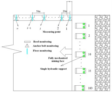
Fig. 6Variation characteristics of bolt tension
2.4. Proportioning and performance of cement slurry
The water used for large deformation soft rock stratum has high humidity, and the viscosity will change significantly after being affected by flowing water [12]. The slurry poured from glass fiber reinforced nylon bolt needs to focus on slurry running and slurry string [13]. Therefore, it is proposed to mix appropriate sodium silicate into the slurry to improve the bonding efficiency and compressive strength of the slurry. The slurry matrix is Portland cement slurry. The difference of water cement ratio has important effects on the parameters such as setting cycle, petrochemical rate and bearing limit. For example, in the soft rock stratum with large amount of water, the slurry with high condensation efficiency can not only effectively reduce the impact of water flow, but also more stably connect the constant resistance device with the rock stratum, reduce the shear stress and improve the creep problem of surrounding rock, so as to effectively ensure the constant resistance function of anchor bolt.
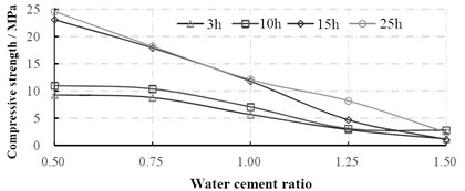
Sodium based material with modulus of 2.8 is used as the water glass in the slurry. According to the test, the best average concentration in the slurry is 40 %. The initial setting time, stone rate and compressive strength under different water cement ratio are shown in Fig. 7 and Fig. 8 respectively. The research shows that when the water cement ratio is lower than 0.5, the grouting of slurry in the anchor bolt will produce huge resistance and the problem of pipeline blockage is serious. When the water cement ratio is greater than 1.5, the stone solidification efficiency of the slurry decreases sharply, and the compressive strength cannot meet the support requirements. When the water cement ratio increases, the stone rate and the compressive strength decreases, the initial setting time increases. The compressive strength of the slurry after setting for 15 h is obviously greater than 10 h, but the gap between them decreases with the increase of water cement ratio.
Fig. 7Variation characteristics of initial setting time and stone rate
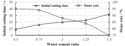
Fig. 8Variation characteristics of compressive strength
3. Test of dynamic stability of anchor bolt support
3.1. Rock burst analysis
In order to verify the reinforcement effect of segmented constant resistance anchor bolt on large deformation rock stratum, the crushing expansion coefficient is tested at different distances from the working face. The crushing expansion coefficient refers to the ratio of the volume of soft rock loosening and expansion to the initial volume under the action of active load. It can be used to predict the probability of overburden cracks, delamination, caving and other problems. According to the construction technology of anchor bolt and the mechanical characteristics of rock stratum, the following steps are followed to test the crushing expansion coefficient:
(1) After the location of the measured point is selected, move the single column hydraulic support. At this time, the roof to be mined out will collapse to a stable state by itself, and then the starting height on the side of the roadway will be measured.
(2) The collapse height shall be tested every 4 hours and measured continuously for more than 2 days. If the deviation from the last measurement result is less than 10 mm, the measured height at this time shall be recorded and taken as the stable height .
(3) Install the single column support again, drill the roof and determine the thickness of soft rock layer , then the crushing expansion coefficient after stabilization can be expressed as:
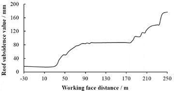
Based on the measured results, the variation curve of crushing expansion coefficient with the advance of working face is drawn as shown in Fig. 9. It can be seen that with the deepening of the advancing surface, the crushing expansion coefficient of soft rock stratum gradually decreases and tends to be stable, and finally maintains a constant value of 1.37. There is no sudden change in the coefficient of crushing expansion among different working faces, which shows that this type of bolt has good reliability for the reinforcement of soft rock stratum. In the test of broken expansion coefficient, the variation law of roof subsidence with different lag working face distance can be obtained at the same time, as shown in Fig. 10. It can be seen that the subsidence of the roof increases intermittently without sudden change, indicating that this type of bolt can effectively ensure the stability of the rock stratum.
Fig. 9Variation of crushing expansion coefficient
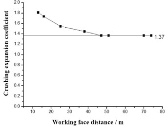
Fig. 10Roof subsidence value
3.2. Seismic performance of the anchor bolt
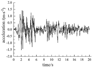
The transient response to blasting vibration can effectively verify the effect of anchor rod resisting earthquake. In order to prove the superiority of segmented constant resistance anchor rod in seismic response, local blasting is used as excitation source to simulate seismic load. Considering the special seismic exploration environment of the mine roadway, 1 seismic source and 4 detection lines are arranged during the vibration test. The detection lines are roof receiving (red line), floor receiving (blue line), coal seam left side receiving (black line) and head-on edge receiving (green line). This test adopts the method of simultaneous receiving by geophones, that is, the , and three component geophones are used for simultaneous receiving. Where, direction is the fault direction. direction is vertical to coal wall. The direction is the base plate direction, of which distance between tracks is 1m. In order to analyze the propagation characteristics of seismic waves in space, the floor source is selected as the excitation source to obtain wave field snapshots at different times, as shown in Fig. 11. It can be seen that the impact radius of blasting is about 50 m. The vibration sensor is installed on the roof of the roadway, with a radial distribution centered on the blasting point, of which interval is 10 m. The displacement caused by blasting is detected by the acceleration sensor. Its time domain characteristics are shown in Fig. 12. The maximum amplitude can be obtained through integral operation.
Fig. 11Snapshot slice of wave field (unit: m)
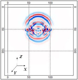
Fig. 12Acceleration change of roof vibration
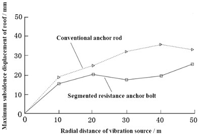
Through the vibration test, the maximum subsidence of the roof in the radial direction under different type bolt support conditions can be obtained, as shown in Fig. 13. It can be seen that the segmented resistance bolt can significantly reduce the roof subsidence. Compared with the conventional bolt, it can reduce the maximum displacement by more than 20 %. Within the range of 30-40 meters from the vibration center, the support effect is more significant.
Fig. 13Maximum subsidence under different radial distances of vibration sources
3.3. Dynamic response test
In order to verify the response ability of anchor bolt to continuous alternating load [14], its dynamic response test scheme is designed, as shown in Fig. 14. Preparing a 1.8 m × 0.6 m × 0.6 m surrounding rock model, in which the interior is concrete slurry layer and the exterior is soft rock layer. Tension sensors are set at different parts of the anchor bolt, alternating inertial excitation force is applied at the end of the anchor bolt, and the pressure and deformation (displacement) are monitored at the same time. During the implementation of the experimental test, the vibration exciter will release the sinusoidal exciting force. The loading position is the left end face, which is used to simulate the load of the roadway roof. The excitation loading and test cycle is 25 s and the amplitude is 150 N. The signal receiver will obtain the stress response results in different segments respectively.
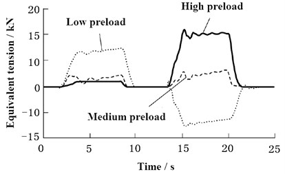
In order to more clearly determine the influence of the preload on the dynamic response, setting the tension sensor firstly to make the tension of each section return to zero before applying the exciting force. Through the test, the variation law of the equivalent tension of the anchor bolt in different preload stages in a single load cycle can be obtained, as shown in Fig. 15. It can be seen that although the response of the anchor bolt to the alternating load in different preload sections is significantly different, the constant resistance effect of each section is significant, and the time to achieve tension stability is less than 1.5 s. The low preload section is most affected by alternating load and its equivalent tension changes periodically. The middle preload section is least affected by the load, and the equivalent tension maintains the overall stability. When the high preload section bears the positive load (consistent with the tension direction), it can maintain very high stability. However, when it bears the reverse load, the equivalent tension value increases significantly, and the direction is opposite to that of the low preload section, so the overall tension change of the anchor bolt is small.
Fig. 14Dynamic response test scheme of anchor bolt
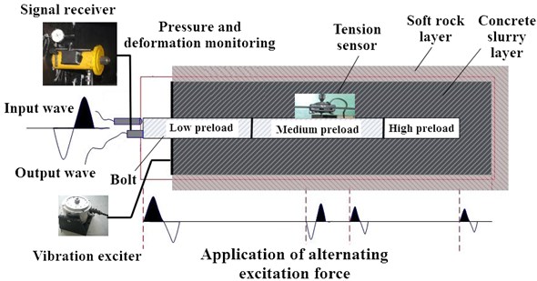
Fig. 15Variation of equivalent tension under alternating load
3.4. Analysis of optimized support effect
When the ultimate tensile load of the segmented constant resistance anchor bolt exceeds the preset value of the constant resistance device, the bolt body will not have excessive deformation or fracture failure [14]. Under the action of multistage prestress, the energy is released more slowly, so as to more effectively buffer the deformation of surrounding rock [15], and greatly reduce the possibility of major accidents such as roof fall and collapse. In large deformation roadway support, the bolt has good application effect, but it usually needs secondary support. In order to further improve the support effect, the following problems can be solved based on the coupling mechanism of strength and stiffness. In the optimization design of bolt structure, in addition to meeting the strength, size and construction requirements, it is also necessary to focus on the factors such as surrounding rock expansion and deformation energy, presplitting blasting impact force, rock internal force transmission and so on. The optimization of grouting should ensure the balance of surrounding rock load, otherwise the local strength is too large and stress concentration will occur. The support of bolt and hydraulic support is a cooperative working mode. Therefore, reasonable layout should be made in the construction process to ensure the stability of soft rock roadway, which requires both sufficient support strength and good support flexibility.
4. Conclusions
In order to effectively improve the anti-seismic problem of large deformation roadway, a multi-stage prestressed segmented constant resistance anchor bolt that suitable for soft rock roadway is proposed according to the support failure principle. Through construction design and engineering test, the reliability of this type of anchor bolt can be effectively verified. The crushing expansion coefficient was tested at different distances from the working face, which can prove the reinforcement effect of this anchor bolt on large deformation rock stratum under stable working conditions. The local blasting was applied as excitation source to simulate seismic load, which can effectively verify the effect of anchor rod resisting earthquake. The dynamic response test scheme was designed, which can obtain mechanical properties of this type of bolt under orthogonal vibration. Under the support of the anchor bolt, the broken swelling coefficient of soft rock shows good stability, and the maximum tension deviation of anchor cable at different positions is less than 7.8 %. This type of bolt has a good release effect on the variable performance of surrounding rock.
References
-
D. K. Pandey, S. K. Mishra, and S. Chakraborty, “A tuned liquid mass damper implemented in a deep liquid storage tank for seismic vibration control of short period structures,” The Structural Design of Tall and Special Buildings, Vol. 31, No. 8, pp. 1928–1932, Jun. 2022, https://doi.org/10.1002/tal.1928
-
A. I. Islamov, R. R. Faskhutdinov, D. Y. Kolupaev, and S. A. Vereschagin, “On the mechanisms of the formation of zones with abnormally high rock pressure and methods for predicting them in undeveloped rock systems, Priobskoye field case study,” Neftyanoe khozyaystvo – Oil Industry, Vol. 10, No. 10, pp. 54–59, 2018, https://doi.org/10.24887/0028-2448-2018-10-54-59
-
H. G. Zhu, C. Yi, and H. Q. Ma, “Influence mechanism of geometric roughness on nonlinear flow in rock mass fractures,” (in Chinese), Journal of Coal, Vol. 42, No. 11, pp. 2861–2866, 2017.
-
A. M. Pavlov and A. A. Fedolyak, “Dynamic rock pressure manifestation: case study,” in IOP Conference Series: Earth and Environmental Science, Vol. 229, No. 1, p. 012014, Mar. 2019, https://doi.org/10.1088/1755-1315/229/1/012014
-
Y. V. Lykov, B. T. Nhu, D. D. Trong, and L. Tung, “Investigation of the suitable dimensions for hydraulic prop support of self-advancing hydraulic roof support in underground mining at Quang Ninh coal basin in Viet Nam,” in Journal of Physics: Conference Series, Vol. 1753, No. 1, p. 012018, Feb. 2021, https://doi.org/10.1088/1742-6596/1753/1/012018
-
Q. T. Chen, Y. Mou, and K. Chen, “Foundation grouting reinforcement technology in open pit combined mining and backfilling area,” (in Chinese), Coal Engineering, Vol. 53, No. 5, pp. 74–79, 2021.
-
J. van Eldert, H. Schunnesson, D. Johansson, and D. Saiang, “Application of measurement while drilling technology to predict rock mass quality and rock support for tunnelling,” Rock Mechanics and Rock Engineering, Vol. 53, No. 3, pp. 1349–1358, Mar. 2020, https://doi.org/10.1007/s00603-019-01979-2
-
R. Czarny et al., “Dispersive seismic waves in a coal seam around the roadway in the presence of excavation damaged zone,” International Journal of Rock Mechanics and Mining Sciences, Vol. 148, p. 104937, Dec. 2021, https://doi.org/10.1016/j.ijrmms.2021.104937
-
C. C. Xue, A. Cao, and W. H. Guo, “Evolution law of mining energy and mechanism of rockburst in deep steep thick coal seam,” (in Chinese), Journal of Mining and Safety Engineering, Vol. 38, No. 8, pp. 876–885, 2021.
-
J. N. Guo, “Surrounding rock instability and high elongation anchor cable control technology of thick coal roof roadway with fully enlarged section,” (in Chinese), Coal and Chemical Industry, Vol. 40, No. 9, pp. 44–46, 2017.
-
S. T. Kadhim and Z. B. Fouad, “Stability analysis of roadway embankments supported by stone columns with the presence of water table under short-term and long-term conditions,” MATEC Web of Conferences, Vol. 162, p. 01013, 2018, https://doi.org/10.1051/matecconf/201816201013
-
X. Han, F. Ye, and X. M. Liang, “Analysis of grouting stratum and slurry particle characteristics behind shield tunnel wall,” (in Chinese), Modern Tunnel Technology, Vol. 57, No. 1, pp. 191–202, 2020.
-
X. P. Ma and J. G. Liu, “Application of comprehensive grouting treatment technology in high pressure water inrush in roadway working face,” (in Chinese), Coal and Chemical Industry, Vol. 39, No. 12, pp. 58–61, 2016.
-
A. Mangal, “A Study of stability investigation of immediate roof for extraction of thick coal seam in India,” Journal of The Institution of Engineers (India): Series D, Vol. 102, No. 1, pp. 203–221, Jun. 2021, https://doi.org/10.1007/s40033-021-00264-3
-
Z. F. Wang, “Research and application of secondary roadway support technology for large section open cut in hard roof,” (in Chinese), Shandong Coal Technology, Vol. 39, No. 10, pp. 10–11, 2021.
Cited by
About this article

The paper is supported by Scientific Research Fund of Binzhou University (BZXYLG2101), National Natural Science Foundation of China (52075047) and Shandong Natural Science Foundation (ZR2019PEE021).
