Abstract
In view of the current poor seismic performance of bridges, this paper started with the vibration isolation and reduction mechanism of the bearing, and deduced the coordination relationship between the stress and the deformation of the bearing under the vibration isolation and vibration reduction working conditions. Combined with the shaking table test, the defect that the traditional rubber bearing has poor seismic isolation effect was analyzed. Based on this, a base-bearing double reduction system was proposed and its vibration reduction and isolation effect was compared with the traditional bearing. The shaking table test results showed that, compared with the traditional bearing, the proposed vibration reduction system had better energy dissipation effect and could weaken the apparent cracking damage of the pier under the action of earthquake. Under the 125 m/s2-750 m/s2 peak acceleration excitation of the EI-Centro wave, the proposed vibration reduction system could greatly reduce the displacement variation of the upper main beam by 20 %-47 %. Moreover, the results of dynamic amplification factor measured at the corresponding height of the two types of piers also verified that the proposed base-bearing double vibration reduction system had greater competitiveness when the peak acceleration of seismic waves was less than 500 m/s2.
Highlights
- A base-bearing double reduction system was proposed and its vibration reduction and isolation effect was compared with the traditional bearing.
- The macroscopic damage pattern of the bridge pier under the action of earthquake was analyzed.
- The displacement change of the upper main beam of the bridge under earthquake action was analyzed after the double damping system of the foundation support was adopted.
1. Introduction
Earthquake damage is a typical form of geological disasters, which brings major challenges to the safe operation of bridges [1-2]. For example, in the Northridge earthquake in the United States, the Hanshin earthquake in Japan and the Wenchuan earthquake in China, bridges have been damaged to varying degrees. According to relevant statistics, in the Northridge earthquake and the Hanshin earthquake, the pier damage accounted for a large proportion, but the bridge damage in the Wenchuan earthquake mainly concentrated in the form of falling beam, bearing displacement and block damage, and the pier damage only accounted for 2.4 % [3]. According to relevant scholars' literature [4-5], a large number of medium and small-span curved bridges were built in Wenchuan, Sichuan Province, China in the late 1990s, and rubber bearings were mostly used to connect the piers and the main beams. This type of connection belonged to the separated connection method, which was different from the pier and beam consolidation system recommended in the AASHTO code, and showed decent anti-seismic effect in the Wenchuan earthquake. This result showed that the “weak” connection design of the plate rubber bearing to the upper and lower structures of the bridge could effectively dissipate the seismic force, and the frictional sliding of the bearing could also play an important role in vibration isolation and energy dissipation. Meanwhile, the anti-falling beam measures and ductility design set on some bridges can also improve their anti-seismic capacity to a certain extent [6-7].
Due to its low price and great anti-seismic effect, plate rubber bearing is widely used in the design of various building architectures and bridges. Many scholars have carried out researches on structural materials and mechanical properties based on it [8-9]. Pedro [10] research showed that low temperature would lead to the hardening of the rubber material in the rubber bearing, thus leading to more seismic force transmission and reducing the vibration isolation effect of the bearing. In terms of the reduction and isolation of bridge bearings, a great effort is currently done to adopt recycled rubber bearings [11, 12] and to simulate their typical coupled biaxial hysteretic response [13] (a crucial modeling aspect for bridges). Abe [14] compared the cyclic mechanical properties of three typical rubber bearings under multi-axial loading, namely ordinary rubber, high damping rubber and lead rubber, and found that the horizontal restoring force of the bearing had a significant coupling effect, and the influence of triaxial loading was not negligible and must be considered in the seismic design of bridges.
Due to the unpredictability of earthquakes, it is obviously one-sided and insufficient to only carry out the anti-seismic design of bridge structures in terms of materials and mechanical properties. In the seismic research of bridges, the use of shaking table tests to simulate real earthquakes is the most direct and effective method to study the seismic response and catastrophic mechanism of bridge structures currently [15], and it is also an important means to evaluate the seismic isolation effect of various components [16-17].
Relying on the bridge shaking table test, this paper started with the seismic isolation mechanism of the bearing, and further verified the defect of the traditional rubber bearing by analyzing the macroscopic damage pattern of the bridge pier under the action of earthquake. Based on this, a base-bearing double vibration reduction system was proposed and used in the earthquake resistance of bridge structure, and the analysis of the displacement time history of the main beam at the top of the pier and its dynamic amplification factor demonstrated that the vibration reduction system proposed in this paper was effective and could be further applied and promoted in the seismic design of bridges.
2. Working mechanism of bearing
In order to deeply analyze the working mechanism of vibration isolation and reduction of the bearing, taking the plate rubber bearing as an example, both the vibration isolation of the bearing and the vibration reduction of the bearing were investigated [18]. Under the influence of horizontal seismic waves, the bridge foundation and the substructure would produce large horizontal displacement, and the instantaneous accumulation of strong energy would lead to strong force on the contact surface between the support and the substructure, and the magnitude of this force was related to the earthquake excitation.
2.1. Bearing vibration isolation stage
If the horizontal thrust on the contact surface is small and the bearing does not change in position, according to the classical mechanics principle, the horizontal force is smaller than the maximum static friction force , and the maximum load is called the bearing critical failure force . In less than the critical failure load, the bearing is mainly subjected to shear deformation, this is the bearing vibration isolation stage, and the shear deformation of the bearing is shown in Fig. 1.
Fig. 1Shear deformation of the bearing
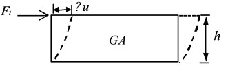
According to the shear deformation diagram of the bearing, the equation for calculating the theoretical value of the bearing shear stiffness is [19]:
The resulting displacement can be calculated as follows:
is the shear deformation modulus of the bearing; is the cross-sectional area of the bearing; is the cumulative height of the bearing; is the shear deformation section coefficient of the bearing, which is 1.2 when the section is rectangular, and 10/9 when the section is circular. is the transverse shear force of the bearing.
According to the shear deformation of the bearing under external load, its critical failure force is:
where is the friction coefficient of the bearing, is the equivalent mass transferred from the upper structure to the bearing, and is the acceleration of gravity.
Substituting Eq. (3) into Eq. (2), the shear deformation of the bearing under the action of external load can be obtained as follows:
According to the relevant provisions of the limit state of normal use, the bridge should maintain a stable state during normal use, there exits no relative slide between the support and the upper and lower structures. This regulation indicates that the transverse shear force at the bearing is far less than the critical failure force when the bridge is working normally, so the value of will not be too small. In addition, in the operation stage after the bridge is completed, the mass change of the superstructure is tiny, and it is necessary to increase the friction coefficient to ensure that the bearing does not have sliding displacement.
2.2. Bearing vibration reduction stage
Under the action of large external loads such as earthquake and collision, the shear force transferred from the lower pier to the bearing is greater than the critical failure load , which leads to slip movement on the contact surface between the bearing and the main beam under the action of external load. This is the bearing vibration reduction stage, and its working diagram is shown in Fig. 2.
Fig. 2Diagram of bearing vibration reduction
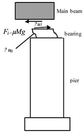
When the main beam and the bearing slip, it can be known from Eq. (3) that the magnitude of the transverse shear force depends on the mass of the upper main beam and the coefficient of kinetic friction . Since the absolute acceleration generated during the sliding process is , the dynamic friction coefficient should be minimized when the bearing slides.
In this case, the relative displacement of the main beam and the bridge pier is composed of the shear deformation of the bearing and the sliding displacement between them:
It can be known from Eq. (2) that , the maximum value of shear deformation of the bearing depends on the shear deformation section coefficient and the critical load value. is the transverse maximum safe distance between the main beam and the pier.
According to Eq. (5), when the upper main beam and lower pier produce excessive shear displacement, the main beam will face falling failure. Therefore, in order to avoid the failure of the falling beam, transverse blocks on both sides of the main beam will be set when constructing bridges.
The maximum sliding displacement between the main beam and the block can be obtained from Eq. (6):
The purpose of setting the transverse block is to prevent the bridge from generating excessive transverse shear force under the action of strong earthquake, resulting in the damage of the falling beam, so this kind of inhibiting device can improve the seismic performance of the bridge to a certain extent. For improving the life of the block and reducing the displacement of the main beam of the bridge structure under the condition of minor disturbance and vehicle vibration, should not be set too small. According to the energy dissipation theory [20], a large amount of energy will be released when the main beam moves or even collides with the block. Therefore, in order to improve the seismic effect, on the one hand, a certain distance should be kept between the main beam and the transverse block to consume seismic energy through sliding friction. On the other hand, the use of UHPC (Ultra-High Performance Concrete) or high-strength steel transverse retaining blocks and installation of anti-falling beam chains can also resist earthquake damage [21-23].
2.3. Working mechanism
The rubber bearing used in this paper was a kind of non-linear elastic material, which was difficult to be simulated by conventional mechanical model. For this kind of material, its hysteretic mechanical properties are an important criterion to measure its energy dissipation and vibration reduction performance. In view of this, bilinear model, Ramberg-Osgood model and Bouc-Wen model were proposed to describe its hysteretic mechanical behavior. The bilinear model is mainly suitable for nonlinear static and dynamic calculations. Before and after yielding, the bearing’s shear stiffness is weakened and decreased. Before reaching the limit, the bearing can be cyclically deformed and reset. The specific hysteresis model is shown in Fig. 3.
Fig. 3Bilinear hysteresis model of the bearing
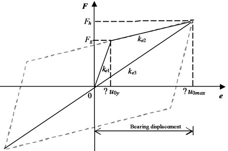
Referring to the relevant provisions of Japanese seismic design code [24], the load before and after bearing yield can be obtained from the following equations:
where is failure load, is ultimate load, is cross-sectional area of rubber in the bearing, is cross-sectional area of lead in the bearing, is pre-yield stiffness, is post-yield stiffness, is equivalent stiffness, is difference coefficient of stiffness before and after yielding, is lead shear stress corresponding bearing yielding, is ultimate shear stress of the lead in the bearing related to the shear deformation , is shear deformation modulus, is failure shear deformation, is ultimate shear deformation.
3. Shaking table test design
3.1. Parameter setting
In order to study the failure form and characteristics of bridge structures under earthquake, lightweight aggregate ceramsite was used to prepare concrete materials in the present study. The selection of specific structural raw material parameters is shown in Table 1. In addition, the bearing was a plate type rubber bearing, the shear stiffness in the horizontal direction was 2.88×10⁵N/m, and the shear stiffness in the vertical direction was 5.61×10⁷N/m.
Table 1Material parameters of bridge components
Component | Main beam | pier |
Longitudinal ribs (type-diameter/mm) | ||
Stirrups (type-diameter/mm) | ||
Concrete (Aggregate Category-Unit weight/kg/m3) | Lightweight aggregate ceramsite-2200 | |
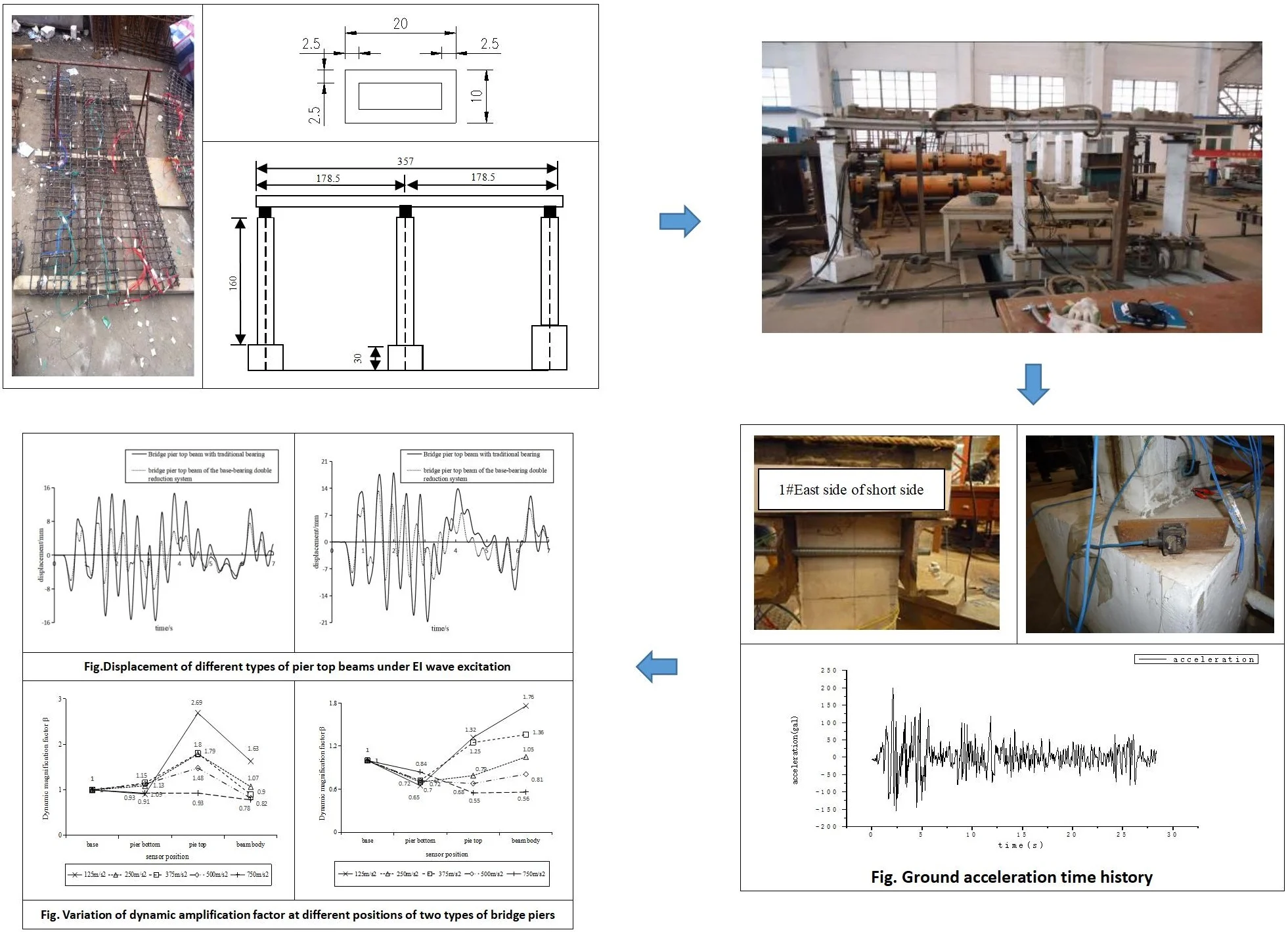
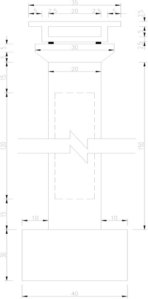
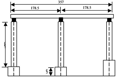
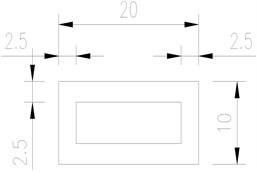
Referring to the relevant case of small box girder, the upper small box girder and the lower hollow rectangular pier components with a scale of 1:20 were designed and manufactured. The specific design and component dimensions are shown in Fig. 4.
Fig. 4Design and dimensions of the components of the bridge (units: cm)
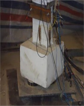
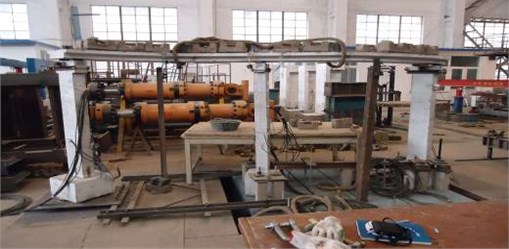
The gantry crane was used for on-site assembly and construction, and the pier manufacture and the field model are shown in Fig. 5.
3.2. Selection of seismic waves
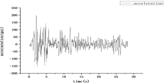
Since the surrounding strata in the author’s area are mainly cohesive soil, the site conditions of the bridge were assumed to be class II in this test based on the relevant provisions of the Code for Seismic Design of Buildings GB50011-2010 [21]. According to the characteristics of class II site, the EI-Centro wave was used as the shaking table input seismic wave, and the ground acceleration time history is shown in Fig. 6. According to the characteristics of the bridge structure, the input seismic acceleration time history data was increased 1.5 times so as to obtain more significant structural dynamic response data.
Fig. 5Pier manufacture and field model
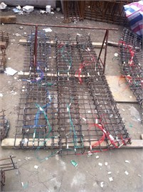
a) Steel binding
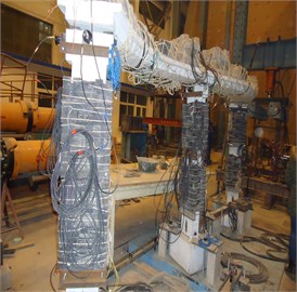
b) Overall counterweight layout of the bridge
Fig. 6Ground acceleration time history
4. Design of base-bearing double vibration reduction system
4.1. Specific layout
In most of the conventional structural anti-seismic experiments, the bridge under structure is fixed on the platform by steel rods and bolts or by drilling bolts in advance. This fixing method can stably consolidate the overall structure of the bridge and the shaking table surface, so it is widely used in shaking table experiments of various engineering structures.
This method can well transmit the simulated seismic excitation of the shaking table to the bridge structure itself, but this is a rigid connection with poor energy dissipation effect. Therefore, in order to improve this design defect, reduce the adverse effects of seismic loads on the structure, and improve the overall seismic isolation performance of the bridge, a base-bearing double vibration reduction system was proposed. The specific layout and working mechanism are shown in Fig. 7.
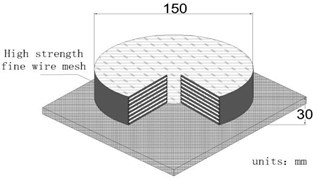
Comparing Fig. 7(a) and Fig. 7(b), it can be seen that in order to improve the seismic performance of the upper main beam of the structure, the traditional bearing was upgraded to a base-bearing double vibration reduction system. A number of energy-dissipating rubber blocks, belonging to the family of elastomeric bearings [26], were added on the shaking table surface and the bottom of the pier base to form a base vibration isolation system. The specific size of the rubber blocks and site layout are shown in Fig. 8. Xue [27] conducted static and dynamic shear tests on square and round rubber specimens with a thickness of 1 cm-4 cm, and the results showed that the energy dissipation modulus of the specimens reached the maximum when the thickness was about 3 cm. Therefore, a rubber bearing with a thickness of 3 cm and a parameter of GYZ 150×30 was selected as the test object, which has the advantages of simple structure, low cost, great impact damping performance, easy installation, reliable working performance, fair earthquake resistance, etc.
Fig. 7Layout and working mechanism of the reduction and isolation system
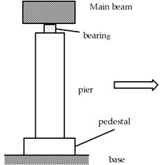
a) Traditional

b) Base-bearing double vibration
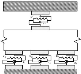
c) Base-bearing double vibration
Fig. 8Size and site layout of energy-dissipating rubber block
b) Installation and location of energy dissipative rubber blocks
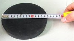
a) Dimensions and construction of energy dissipative rubber blocks
4.2. Shaking table loading scheme
The most important part of shaking table test is to select appropriate seismic waves for input. Considering the acceleration amplitude, duration and spectral characteristics, EI-Centro seismic waves were selected for the shaking table test. In order to simulate the failure response of the structure and the seismic reduction and isolation effect of the bearing under different seismic intensities, the seismic excitation of 6 degrees, 7 degrees, 8 degrees with frequent and rare intensities was set in this shaking table test, and the corresponding peak acceleration values were 125 m/s2, 250 m/s2, 500 m/s2 and 750 m/s2, respectively. And at the end of each level of working condition, the sine wave of the fundamental frequency of the structure is input by hammering, which makes the failure form appear clearer in the next level of loading condition.
In order to meet the test effect, the quasi-dimensional analysis method was adopted for model design. The geometric dimension, equivalent stress and acceleration were used as control similarity constants in the bridge model. According to the design calculation, the geometric dimension coefficient is 1/20, the equivalent stress coefficient is 0.63768, and the acceleration coefficient is 1.5.
After calculating the counterweight of the bridge structure, the mass and counterweight of each part are shown in Table 2, and the bridge model on the vibration table is shown in Fig. 9.
Table 2Test model counterweight
Component | Prototype weight (t) | Model weight (kg) | Counterweight (kg) | Concrete pedestal (kg) | Connector (kg) |
Beam | 135.275 | 149.85 | 1287.88 | 178 | 93.4 |
Pier | 133.95 | 304.095 | 1119.505 | ||
Total | 269.225 | 453.945 | 2407.385 | ||
Test Model weight (kg) = 453.945+2407.385+178+93.4 =3132.73 kg | |||||
Fig. 9Bridge model on the vibration table
4.3. Collection of natural frequency
The natural vibration frequency of the bridge structure is collected before each level of loading of different seismic intensity excitations, so as to better analyze the dynamic characteristics of the bridge structure. The obtained dynamic characteristics are shown in Table 3.
Table 3Natural vibration frequencies of bridge structures
Working condition | Peak acceleration in m/s2 | Traditional bearing pier side | Base-bearing double isolation pier side | ||
Natural frequency in Hz | Drop | Natural frequency in Hz | Drop | ||
0 | 0 | 5.7 | 0 | 5.62 | 0 |
1 | 125 | 5.62 | 1.40 % | 4.7 | 16.37 % |
2 | 250 | 3.72 | 34.74 % | 3.62 | 35.59 % |
3 | 375 | 3.7 | 35.09 % | 3.6 | 35.94 % |
4 | 500 | 2.74 | 51.39 % | 2.74 | 51.25 % |
5 | 750 | 2.74 | 51.39 % | 2.74 | 51.25 % |
The following points can be drawn from Table 3:
(1) With the increase of seismic intensity, the bridge structure was damaged to different degrees, and the natural vibration frequency of the structure showed a downward trend;
(2) Under different working conditions, there was no significant difference in the natural vibration frequencies near the two types of bridge piers, indicating that the natural vibration frequencies of the structures were more related to their own mass and stiffness, but less related to the foundation type of the structure.
(3) With the increase of seismic intensity in the test, the natural vibration frequencies of the structures near the two types of bridge piers had a certain difference under the excitation of 125-375 m/s2 peak acceleration, but after the peak acceleration exceeded 500 m/s2, the measured frequencies were basically the same, indicating that the base-bearing double vibration reduction system used in the test was competitive under small earthquake conditions, but other auxiliary methods were needed under strong earthquake action.
5. Test verification
5.1. Damage description of bridge piers
The failure modes of the piers under the EI-Centro wave 375-750 m/s2 peak acceleration were compared between the traditional support and the base-support double vibration reduction system. The pier status and sensor layout are shown in Fig. 10.
Under the EI wave 375 m/s2 peak acceleration with the 1# traditional bear layout, the cracks originated from the west side of the pier’s long side, and two transverse cracks with lengths of 12 cm and 6 cm appeared at 10 cm from the pedestal. With the increase of peak acceleration, the cracks tended to develop upward, and were concentrated at the height of 10-60 cm from the pedestal, presenting transverse and oblique distribution.
Under the EI wave 375 m/s2 peak acceleration with 3# base-bearing double vibration reduction system, a transverse crack of about 10 cm in length appeared on the north side of the short side 22 cm away from the pedestal, and then a transverse crack of about 12 cm in length appeared through the other side.
Fig. 10Pier status and sensors layout
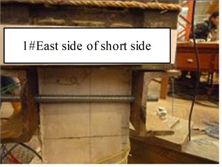
a) Status of the east side of the short side of pier 1#
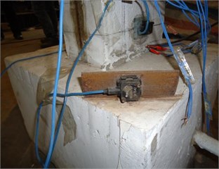
b) The vibration picker on the base
5.2. Vibration reduction effect of bridge pier
Displacement sensors were installed at the top of the two types of bridge piers, and seismic excitation with peak acceleration of 125 m/s2-750 m/s2 was input to the shaking table. The maximum displacement of the beam obtained is shown in Table 4.
Table 4Comparison of seismic effects of different types of bridge piers under El wave action (unit: mm)
Measuring point location | seismic peak acceleration | ||||
125 m/s2 | 250 m/s2 | 375 m/s2 | 500 m/s2 | 750 m/s2 | |
Bridge pier top beam with traditional bearing | 6.62 | 9.34 | 14.65 | 17.98 | 29.8 |
Bridge pier top beam of the base-bearing double reduction system | 3.86 | 7.11 | 7.76 | 13.4 | 23.72 |
Drop | 42 % | 24 % | 47 % | 25 % | 20 % |
As can be seen from Table 4, with the increase of seismic intensity, the maximum displacement measured at the pier top main beam also increased. By comparing the displacement data of the two kinds of pier top beams, the displacement variation of the upper main beam could be greatly reduced by using the proposed reduction method, with a reduction range of 20 %-47 %, reflecting the prominent competitiveness of the proposed reduction system. In addition, the results of the reduction amplitude under different seismic intensities also showed that the proposed reduction system was more competitive when the peak acceleration of seismic waves was at a lower level (< 500 m/s2).
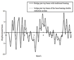
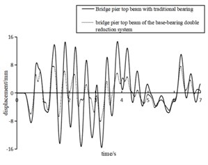
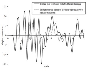
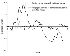
Under the peak acceleration of EI wave of 125-750 m/s2, the displacement time history curves of the two types of pier top beams are shown in Fig. 11. Due to space limitation, only 7 seconds of data captured are listed here.
Fig. 11Displacement of different types of pier top beams under EI wave excitation with peak acceleration of 125- 750 m/s2
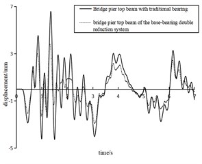
a) 125 m/s2
b) 250 m/s2
c) 375 m/s2
d) 500 m/s2
e) 750 m/s2
Fig. 11 intuitively manifests that the vibration reduction system proposed in this paper was more competitive than the traditional method. For the displacement time history parameters, the reduction system performed better under the seismic intensity of 125-750 m/s2. Compared with the traditional single-bearing pier, the proposed base-bearing double reduction system had better damping performance and better dissipative property to the peak response time domain, so that the structure could maintain a more stable amplitude under strong earthquakes, as shown in Fig. 11(e).
6. Dynamic magnification factor
The dynamic amplification factor is a kind of seismic analysis parameter using the single mass point system, which is suitable for the vibration analysis of the high-rise components such as bridge piers. This factor can be expressed as the ratio of the maximum acceleration value of the target measuring point to the maximum value of ground acceleration under earthquake action, and its value can be obtained by the following formula:
where is the maximum value of acceleration measured at the target measuring point; refers to the maximum value of acceleration under the corresponding working condition, here refers tot he peak value of acceleration measured on the vibration table.
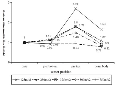
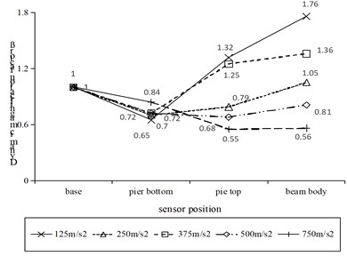
The horizontal acceleration data collected by inputting El-Centro wave under the excitation of 125 m/s2-750 m/s2 peak acceleration were processed, and the dynamic amplification factor of different parts such as the pier bottom, pier top, and beam body corresponding to the two types of piers were acquired as shown in Fig. 12.
Fig. 12Variation of dynamic amplification factor at different positions of two types of bridge piers
a) Traditional bridge pier conditions
b) Pier conditions with base-bearing double reduction system
Fig. 12(a) shows the variation of the dynamic amplification factor at different positions of the traditional bridge pier under different seismic loading conditions. It can be observed that dynamic amplification factor increased first and then decreased with the height of the structure, and showed an increasing trend from the base along the pier. The amplification factor reached the maximum at the top of the pier, and then decreased at the beam position. Analysis of Fig. 12(a) shows that the traditional bridge pier was fixed on the shaking table to form a rigid connection, so its amplification factor presented an increasing trend along the height, and the seismic energy was released through the vibration reduction and energy dissipation of the bearing, and thus the amplification factor of the beam body showed a decreasing trend.
Fig. 12(b) shows the variation of the dynamic amplification factor at different positions of the piers of the base-bearing double vibration reduction system under different seismic loading conditions. When the seismic intensity was loaded from 125 m/s2 to 500 m/s2, the dynamic amplification factor first decreased and then increased along the height, and the dynamic amplification factor of the acceleration at the measuring point at the pier bottom was the smallest, reflecting the remarkable effect of the base damping device proposed in the present study. In the propagation process from the top of the pier to the beam, the acceleration amplification factor did not decrease, but increased, indicating that the effect of pier top bearing was basically negligible for the damping of pier bottom. When more than 500 m/s2 seismic intensity was loaded to the pedestal, the dynamic amplification factor of the structure basically decreased along the height, indicating that the damping effect of pier top bearing could be exerted under strong earthquake excitation, and the frictional slip of pier top bearing could greatly release energy, so that the dynamic amplification factor of the corresponding measuring points continued to decrease.
In addition, comparing Fig. 12(a) and Fig. 12(b), it can be seen that with the increase of seismic intensity, the dynamic amplification factor of the measuring point position along the height showed a decreasing trend, indicating that the structure was damaged during the vibration process and part of the energy was dissipated, also leading to the reduction of the peak acceleration.
7. Conclusions
Based on a shaking table test carried out on a bridge structure, the seismic effect of the seismic reduction isolation system proposed in this paper was verified by analyzing the failure modes of the bridge pier and its upper main beam under different seismic intensities, and the following beneficial conclusions were drawn:
1) With the increase of the seismic intensity, the bridge damage was further aggravated, which was manifested as the decrease of the measured natural vibration frequency and the aggravation of the apparent cracking damage.
2) Compared with the traditional bearing, the proposed base-bearing double vibration reduction system could greatly reduce the displacement variation of the upper main beam under earthquake action, and the maximum reduction range was 20 %-47 %.
3) Compared with the traditional single bearing, the base damping mechanism played the main role when the seismic intensity was below 500 m/s2, and the bearing damping mechanism played the main role when the seismic intensity was above 500 m/s2.
4) With the increase of seismic intensity, the dynamic amplification factor corresponding to different positions of bridge piers presented a decreasing trend. It shows that with the increase of earthquake severity, the structure would be damaged to different degrees, and the dynamic amplification factor would gradually decrease, indicating that there was a certain correlation between the dynamic amplification factor of structural acceleration parameter and seismic intensity.
5) In future studies, it is necessary to propose accurate models [28, 29] to predict the experimental responses and check if the selected design parameters are suitable for the specific application.
6) In next work, it is crucial to investigate the rocking effects that it is possible to have in the proposed solution.
References
-
H. Chang, L. Liu, L. Jing, J. Lu, and S. Cao, “Study on damping performance of hyperboloid damper with SMA-negative stiffness,” Buildings, Vol. 12, No. 8, p. 1111, Jul. 2022, https://doi.org/10.3390/buildings12081111
-
J. Z. Li and Z. G. Guan, “Research on bridge seismic design: target from seismic alleviation to post-earthquake structural resilience,” (in Chinese), China Journal of Highway and Transport, Vol. 30, No. 12, pp. 1–9, 2017, https://doi.org/10.19721/j.cnki.1001-7372.2017.12.001
-
L. S. Chen, W. L. Zhuang, H. Q. Zhao, and Z. J. Wan, Damage of highway in Wenchuan earthquake-bridges. (in Chinese), Beijing: China Communications Press, 2012.
-
K. H. Wang, C. Li, Q. Li, and Y. Li, “Seismic design method of small and medium span bridge considering bearing friction slipping,” (in Chinese), Engineering Mechanics, Vol. 31, No. 6, pp. 85–92, 2014, https://doi.org/10.6052/j.issn.1000-4750.2012.12.0939
-
D. S. Wang, X. Guo, Z. G. Sun, Q. L. Meng, D. H. Yu, and X. L. Li, “Damage to highway bridges during Wenchuan earthquake,” (in Chinese), Earthquake Engineering and Engineering Vibration, Vol. 29, No. 3, pp. 84–94, 2009, https://doi.org/10.13197/j.eeev.2009.03.004
-
Q. Tian, T. Hayashikawa, G.-Q. Song, and C. Zhang, “Study on the effect of cable restrainers stiffness on the seismic performance of curved viaducts combined use of steel stoppers,” Journal of Earthquake and Tsunami, Vol. 13, No. 2, pp. 1–16, Apr. 2019, https://doi.org/10.1142/s1793431119500064
-
M. R. H. B. Araghi and S. M. Zahrai, “Seismic design and performance of ductile end-diaphragms in slab-on-girder steel bridges with flexible substructure,” Journal of Bridge Engineering, Vol. 22, No. 11, p. 04017098, Nov. 2017, https://doi.org/10.1061/(asce)be.1943-5592.0001132
-
M. Kikuchi and I. D. Aiken, “An analytical hysteresis model for elastomeric seismic isolation bearings,” Earthquake Engineering and Structural Dynamics, Vol. 26, No. 2, pp. 215–231, 1997, https://doi.org/10.1002/(sici)1096-9845(199702)26:2
-
A. D. Nguyen, “A rheology model of high damping rubber bearings for seismic analysis at room and low temperatures,” Saitama University, 2017.
-
P. A. C. Bandini, G. H. Siqueira, J. E. Padgett, and P. Paultre, “Seismic performance assessment of a retrofitted bridge with natural rubber isolators in cold weather environments using fragility surfaces,” Journal of Bridge Engineering, Vol. 27, No. 6, p. 04022040, Jun. 2022, https://doi.org/10.1061/(asce)be.1943-5592.0001873
-
D. Losanno, F. Palumbo, A. Calabrese, T. Barrasso, and N. Vaiana, “Preliminary investigation of aging effects on recycled rubber fiber reinforced bearings (RR-FRBs),” Journal of Earthquake Engineering, Vol. 26, No. 10, pp. 5407–5424, Jul. 2022, https://doi.org/10.1080/13632469.2021.1871683
-
D. Losanno et al., “Recycled versus natural-rubber fiber-reinforced bearings for base isolation: review of the experimental findings,” Journal of Earthquake Engineering, Vol. 26, No. 4, pp. 1921–1940, Mar. 2022, https://doi.org/10.1080/13632469.2020.1748764
-
N. Vaiana, D. Losanno, and N. Ravichandran, “A novel family of multiple springs models suitable for biaxial rate-independent hysteretic behavior,” Computers and Structures, Vol. 244, p. 106403, Feb. 2021, https://doi.org/10.1016/j.compstruc.2020.106403
-
M. Abe, J. Yoshida, and Y. Fujino, “Multiaxial behaviors of laminated rubber bearings and their modeling. I: experimental study,” Journal of Structural Engineering, Vol. 130, No. 8, pp. 1119–1132, Aug. 2004, https://doi.org/10.1061/(asce)0733-9445(2004)130:8(1119)
-
L. Xu, K. Liu, C. Zhang, J. Zheng, C. Wang, and Q. Huang, “Experimental study of seismic mitigation of a large-span cable-stayed bridge with elastic cables by shaking table test,” Practice Periodical on Structural Design and Construction, Vol. 26, No. 2, p. 04021006, May 2021, https://doi.org/10.1061/(asce)sc.1943-5576.0000573
-
N. Xiang and M. S. Alam, “Comparative seismic fragility assessment of an existing isolated continuous bridge retrofitted with different energy dissipation devices,” Journal of Bridge Engineering, Vol. 24, No. 8, p. 04019070, Aug. 2019, https://doi.org/10.1061/(asce)be.1943-5592.0001425
-
W. Zhang, R. Fang, S. Chen, and H. Zhao, “Experimental study of the aseismic effect of a locking ball for a continuous bridge,” Journal of Bridge Engineering, Vol. 22, No. 10, p. 04017071, Oct. 2017, https://doi.org/10.1061/(asce)be.1943-5592.0001099
-
Q. N. Li, M. L. Cheng, J. H. Yin, L. Yan, and X. Liao, “Analysis and experimental study on performance of curved bridge sliding seismic isolation,” (in Chinese), World Earthquake Engineering, Vol. 33, No. 1, pp. 34–40, 2017.
-
“JT/T 663-2006, Series of elastometric pad bearings for highway bridges,” China Communications Press, Beijing, 2006.
-
K. L. Deng, P. Pan, T. R. Ran, Y. K. Su, and Y. T. Xue, “Experimental study of energy dissipation stopper for bridge,” (in Chinese), Journal of Vibration and Shock, Vol. 33, No. 22, pp. 7–12, 2014, https://doi.org/10.13465/j.cnki.jvs.2014.22.002
-
Y. Y. Liu, Q. Z. Zheng, L. B. Long, Y. Q. Ma, and G. Chen, “Study on seismic behavior of prefabricated reinforced concrete frames with precast UHPC post-cast joints,” (in Chinese), China Water Transport (Second Half), Vol. 19, No. 5, pp. 222–224, 2019.
-
G. Wu, K. Wang, P. Zhang, and G. Lu, “Effect of mechanical degradation of laminated elastomeric bearings and shear keys upon seismic behaviors of small-to-medium-span highway bridges in transverse direction,” Earthquake Engineering and Engineering Vibration, Vol. 17, No. 1, pp. 205–220, Jan. 2018, https://doi.org/10.1007/s11803-018-0435-z
-
R. Fang, W. Zhang, S. Chen, and H. Zhao, “Seismic resistance of locking ball devices and optimal design for irregular continuous bridges with one fixed pier,” Bulletin of Earthquake Engineering, Vol. 18, No. 5, pp. 2355–2388, Mar. 2020, https://doi.org/10.1007/s10518-020-00788-1
-
“Design specification of Japan highway bridge (Seismic Design),” Mzruzen L.d., Tokyo, Japan Road Association, 2002.
-
“GB 50011-2010, Code for seismic design of buildings,” (in Chinese), China Architecture and Building Press, Beijing, 2010.
-
N. Vaiana, S. Sessa, F. Marmo, and L. Rosati, “An accurate and computationally efficient uniaxial phenomenological model for steel and fiber reinforced elastomeric bearings,” Composite Structures, Vol. 211, No. 1, pp. 196–212, Mar. 2019, https://doi.org/10.1016/j.compstruct.2018.12.017
-
X. F. Xue, Z. T. Hu, and J. X. Liu, “Research on energy dissipation behavior of high damping rubber,” (in Chinese), Journal of Highway and Transportation Research and Development, Vol. 23, No. 3, pp. 70–73, 2006, https://doi.org/10.3969/j.issn.1002-0268.2006.03.017
-
N. Vaiana, S. Sessa, F. Marmo, and L. Rosati, “A class of uniaxial phenomenological models for simulating hysteretic phenomena in rate-independent mechanical systems and materials,” Nonlinear Dynamics, Vol. 93, No. 3, pp. 1647–1669, Aug. 2018, https://doi.org/10.1007/s11071-018-4282-2
-
N. Vaiana and L. Rosati, “Classification and unified phenomenological modeling of complex uniaxial rate-independent hysteretic responses,” Mechanical Systems and Signal Processing, Vol. 182, p. 109539, Jan. 2023, https://doi.org/10.1016/j.ymssp.2022.109539
About this article

This work was partially supported by the Research Project of Jiangxi Provincial Department of Education (GJJ190980) and the scientific research Project of the Communications Department of Shaanxi Province (13-25k).
The datasets generated during and/or analyzed during the current study are available from the corresponding author on reasonable request.
The authors declare that they have no conflict of interest.
