Abstract
Under the requirement of high speed, high pressure ratio and high thrust weight ratio, more and more aircraft engines adopt counter rotating technology. In this model, the F135 engine is used to research the dynamic characteristics of a dual rotor system with four supports supported by an intermediary. In this paper, the critical speed of the system is solved by the direct method. Compared with the Campell diagram, the eigenvalue problem of the required solution is greatly reduced. The critical speed is optimized by using genetic algorithm. Moreover, when the constraint of frequency forbidden zone is more severe, the elitist preserving genetic algorithm is used, which greatly reduces the required convergence algebra.
1. Introduction
The development of modern aircraft has put forward requirements of high speed, high pressure ratio and high thrust-to-weight ratio for aero-engines. In order to further improve the performance of aero-engines, especially the performance of military aero-engines, more and more engines use counter-rotation technology. Such as the US F119 engine, YF120 engine, the British “Pegasus” engine, RB211, GE120 and so on. The use of the counter-rotation technology helps to reduce the impact of the rotor system gyroscopic moment on the maneuvering performance of the aircraft, and thus improve the maneuverability of the aircraft [1].
Critical speed, one of the most important intrinsic characteristics of a rotor system, has been the focus of research. The critical speed is the speed at which the rotor system resonates under its own unbalanced forces. In the initial stage of the rotor system design, the critical speed characteristics of the system must be calculated and optimized to avoid the common speed of the rotor system, such as idle speed, working speed, and limit speed [1]. The current aero-engines mostly use a dual-rotor system, so the rotor system is simultaneously subjected to two different frequency excitation forces. Therefore, the critical speed of the inner rotor as the main excitation and the outer rotor as the main excitation must be considered at the same time.
In this paper, the model refers to the F135 engine and studies the dynamic characteristics of the two-rotor system with four fulcrum supports. Although this support structure can effectively reduce the mass of the engine, it will make its dynamic characteristics more complicated. The low-pressure rotor adopts a 0-1-1 support mode, and the rigidity of the entire low-pressure rotor is reduced; The fulcrum support makes the rotor vibration condition no longer a simple superposition, but a vibrational coupling between the inner and outer rotors [2]. Therefore, the analysis and optimization of the critical speed of the dual rotor support system is very necessary, and the purpose of eliminating dangerous hazards can be achieved.
2. Tester model and theoretical calculations
The double rotor tester is designed as a four-point support. The inner and outer rotor speed ratio is 1.6 and is reverse rotation. The inner (low-pressure) rotor is supported by 0-1-1, while the outer (high-pressure) rotor is supported by 1-0-1. The tester is provided with four adjustable support bearings. The structure diagram of double rotor tester is shown in Fig. 1.
Fig. 1Structure diagram of double rotor tester
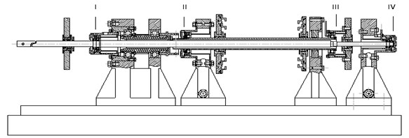
The support stiffness of the rotor system is shown in Table 1. The support I is an inner rotor front support. The support II is a front support of the outer rotor. The support III is an intermediate support. The support IV is a rear support of the inner rotor.
Table 1Support stiffness
Elastic support number | I | II | III | IV |
Stiffness (N/m) | 1.45×10⁶ | 9.29×10⁵ | 2.51×10⁶ | 2.21×10⁵ |
Assume that the equation of motion of the rotor system is in the form of Eq. (1):
where is the mass matrix of the system, is the stiffness matrix of the system, is the damping matrix of the system, and is the gyro matrix of the system. The above matrices are all obtained by the finite element method. is an external excitation matrix [3].
After obtaining the system mass matrix, stiffness matrix, damping matrix and gyro matrix by the finite element method, the critical speed of the rotor system can be calculated by solving the gyro eigenvalue problem. The speed is plotted on the abscissa and the corresponding natural frequency is plotted on the ordinate to plot the Campell diagram. However, this method needs to solve the eigenvalue problem once at each speed, the calculation takes a long time, and the solution efficiency is low [3]. Therefore, this paper uses the direct method to solve the critical speed of the system.
Eq. (2) is about the eigenvalue problem, and the corresponding critical speed can be obtained by solving it:
For a single-rotor system, let 1 and solve for the critical speed of the system. For the dual-rotor system, since there are two frequencies of excitation force, it is necessary to separately calculate the critical speed of the inner and outer rotors as the main excitation. Let and . Where is the inner rotor speed ratio, is the outer rotor speed ratio. This article takes 1 and –1.6. With this method, only the two eigenvalue problems need to be calculated after the completion of the equation of motion to obtain the critical speed of the dual-rotor system. Compared to the method of drawing a Campell diagram, the calculation time is greatly reduced. Calculation results of direct method and experimental data are shown in Table 2.
It can be seen from Table 2 that the results of the first-order critical speed of the inner rotor as the main excitation is not much different, and the error is 2.46 %. However, the results of the first-order critical speed of the outer rotor as the main excitation is quite different, and the error is 7 %. The increase in error here is due to the inaccurate prediction of the stiffness of the intermediate support.
Table 2Calculation results of direct method and experimental data
Inner rotor as main excitation | Direct method (rad/s) | Experimental data(rad/s) | Outer rotor as main excitation | Direct method(rad/s) | Experimental data(rad/s) |
First order | 169.1527 | 173.747 | First order | 174.8578 | 189.447 |
Second order | 284.1933 | – | Second order | 271.4994 | |
Third order | 579.6269 | – | Third order | 605.5842 |
3. Critical speed optimization
This paper uses genetic algorithm to optimize the critical speed. Compared with traditional optimization algorithms, intelligent algorithms such as genetic algorithms have the advantages of lower requirements on mathematical models and strong global search capabilities. It is especially suitable for the problem that the design variables and the objective function have no explicit expression [4, 5].
3.1. Objective function and design variable
In this paper, the stiffness of bearing I, II, IV is taken as the design variable, and the deviation of the frequency is as far as possible from the critical speed of each step. The real-time coding genetic algorithm is used to optimize the critical speed characteristics of the rotor system of the tester. Optimization problems can be described in mathematical language as Eq. (3):
where is the objective function. It is used to measure the distance between the critical speed of each step and the frequency exclusion zone. The further the distance, the larger the objective function value. , and are support stiffness. and represent the range of variation of each support stiffness. The subscript 1 indicates the critical speed of the inner rotor as the main excitation, and 2 represents the critical speed of the outer rotor as the main excitation. The subscript 1, 2, …, represents the order of critical speed. is the critical speed. indicates the usual rotational speed closest to .
It is assumed that the first th order critical speed of the rotor system needs to be optimized. First, the first th order critical speed of the system is calculated by the direct method. Then, for each critical speed of the order, calculate the distance from the nearest frequency exclusion zone. Then, for each critical speed of the order, calculate its proximity to the nearest frequency exclusion zone.
The variation range of the rotor support I, II and IV stiffness of the tester is 2.9×10⁵N/m-2.9×106N/m, 1.858×10⁵N/m-1.858×106N/m, 0.442×10⁵N/m-0.442×106N/m. The working speed of the rotor system is shown in Table 3. The corresponding frequency exclusion zone is shown in Table 4.
Table 3Working speed of rotor
– | Idle speed (rad/s) | Working speed (rad/s) | Limit sped (rad/s) |
Situation 1 | 213.52 | 364.24 | None |
Situation 2 | 188.4 | 376.8 | 521.24 |
This article sets the frequency exclusion zone for two Situations. The frequency exclusion zone of Situation 1 is relatively loose, and only the first-order critical speed of the inner and outer rotors falls within the frequency exclusion zone and is very close to the frequency exclusion zone boundary. The frequency exclusion zone of Situation 2 is stricter, and the first-order and third-order critical speeds all fall within the frequency exclusion zone and are far from the boundary of the frequency exclusion zone. In this paper, the optimization of the first three critical speeds of the tester rotor system is carried out for the above two Situations.
Table 4Frequency exclusion zone
– | Idle speed (rad/s) | Working speed (rad/s) | Limit sped (rad/s) |
Situation 1 | 170.816-256.224 | 211.392-317.088 | None |
Situation 2 | 150.72-226.08 | 301.44-452.16 | 416.992-625.488 |
3.2. Optimization results
Situation 1 is optimized by using genetic algorithm with real number coding. The number of individuals in the population is 30, and the maximum iteration number is 100 generations. The optimization goal is the distance between the first three critical speeds and the frequency exclusion zone.
Fig. 2Situation 1-100 generation optimization results
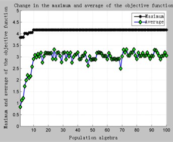
a) Change in the maximum and average values of the objective function
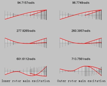
b) Critical speed and corresponding mode of vibration after optimization
The calculation results of Situation 1 are shown in Fig. 2 and Table 5. It can be clearly seen from Fig. 2(a) that because the constraint of the frequency 1 restricted area is loose, there is a feasible solution in the initial population, and the convergence speed is very fast. After only 10 generations the result has converged. The optimized critical speed and support stiffness values are shown in Table 5.
Table 5Situation1 comparison of results before and after optimization
Before optimization | First order (rad/s) | Second order (rad/s) | Third order (rad/s) | |||
Inner rotor | 169.1527 | 284.1933 | 579.6269 | 20.77 % | 21.97 % | 59.13 % |
Outer rotor | 174.8548 | 271.4994 | 605.5842 | 18.10 % | 25.46 % | 66.26 % |
After optimization | First order (rad/s) | Second order (rad/s) | Third order (rad/s) | |||
Inner rotor | 97.7157 | 277.9265 | 601.6112 | 54.24 % | 23.70 % | 64.17 % |
Outer rotor | 96.7748 | 260.3957 | 713.7561 | 54.68 % | 21.95 % | 95.96 % |
As can be seen from Table 5, before the optimization, only the first-order critical speed of the outer rotor falls within the frequency exclusion zone, which does not meet the design requirements. After optimization, the critical speed of each step of the inner and outer rotors is the distance from the frequency exclusion zone to more than 20 %, and the distance between each critical speed and the frequency exclusion zone is increased. Only the second-order critical speed of the main rotor is reduced from 25.46 % to 21.95 %, but still meets the requirement of more than 20 %. The optimized bearing stiffness values are respectively 2.9×10⁶ N/m, 1.858×10⁶ N/m, 0.442×10⁵ N/m.
Situation 2 was optimized in the same way. Due to the limitation of the limit speed, the first four-step critical speed is optimized to prevent the first three critical speed from satisfying the requirements after the optimization and the fourth-order critical speed is not satisfactory. After calculation, it is found that the final optimization of 100 generations yields the optimal result, and the maximum iteration algebra of 50 fails. The calculation results are shown in Fig. 3.
Fig. 3Situation 2-Optimization results
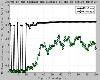
a) 100 generations
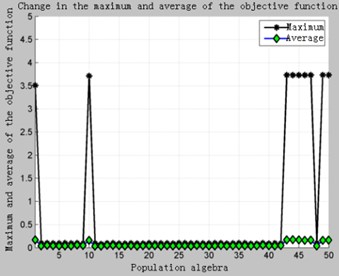
b) 50 generations
As can be seen in the Fig. 3, due to the stricter constraints, there are fewer feasible solutions in the initial population, and the feasible domain of the design variables is narrow. Even if there are viable individuals in the current population, it is very likely that they will disappear during the process of selection, crossover, mutation, and reorganization. It can be seen in the Fig. 3(b). In view of this situation, First, it can be solved by increasing the iterative algebra, but it will increase the computational time and waste the computing resources. Second, it can adopt the elite retention strategy. That is, copy the optimal individual in the current population, and then select, cross, mutate, and reorganize the entire population to obtain a new population. Calculate the fitness value of the new population and compare the worst individuals in the new population with the previous best individuals. Take the one with the highest fitness value to replace the worst individual in the new population. In this way, on the one hand, it is possible to avoid the disappearance of excellent individuals in the process of inheritance, and on the other hand, the speed of convergence can be greatly improved. The optimization results are shown in Fig. 4.
Fig. 4Situation 2-The elite retains 50 generations of computational results
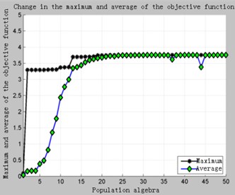
a) Change in the maximum and average values of the objective function
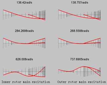
b) Critical speed and corresponding mode of vibration after optimization
Comparing Fig. 3 with Fig. 4, it can be clearly seen that adopting the elite retention strategy can greatly improve the convergence speed under the premise of ensuring optimization.
It only takes about 20 generations to get the optimization results. This is because on the one hand, the elite reservation accelerates the algebra required for the first feasible solution, and the second is that after the first feasible solution appears, the optimal individual in the current population is not lost due to genetic manipulation. It ensures the retention of excellent genes in the population and accelerates the convergence.
Table 6Situation 2 comparison of results before and after optimization
Before optimization | First order (rad/s) | Second order (rad/s) | Third order (rad/s) | |||
Inner rotor | 169.1527 | 284.1933 | 579.6269 | 10.22 % | 24.58 % | 11.20 % |
Outer rotor | 174.8548 | 271.4994 | 605.5842 | 7.12 % | 27.95 % | 16.18 % |
After optimization | First order (rad/s) | Second order(rad/s) | Third order (rad/s) | |||
Inner rotor | 136.42 | 284.2698 | 626.008 | 27.59 % | 24.55 % | 20.10 % |
Outer rotor | 138.757 | 268.5588 | 737.6905 | 26.35 % | 28.73 % | 41.52 % |
Table 6 shows the comparison of critical speed before and after optimization. The upper half of Table 6 is the percentage of the critical speed before optimization and the deviation from the common speed of the rotor system. Among them, the first-order and third-order critical speeds of the inner and outer rotors are mainly in the frequency forbidden zone. After optimization, the critical speeds of each step jump out of the frequency forbidden zone and achieve the purpose of optimization. The optimized bearing stiffness values are respectively 2.9×10⁶ N/m, 1.858×10⁶ N/m, 0.442×10⁵ N/m.
4. Conclusions
This paper is directed to a counter-rotating dual rotor system with intermediate support. The direct method is used to solve the critical speed of the system, and the genetic algorithm is used to optimize the critical speed. The main conclusions are:
1) Compared with the Campell graph method, the number of eigenvalue problems to be solved by the direct method is greatly reduced. And through experiments, the relative error is less than 2.5 % in the first three steps.
2) When the constraints of the rotor system frequency exclusion zone are loose, the traditional genetic algorithm only needs 10-20 generation calculation to get the optimization result. However, when the constraints of the frequency exclusion zone are stricter, traditional genetic algorithms often require more iterative algebras to converge. At this point, switching to the elite retention genetic algorithm can greatly reduce the required convergence algebra.
References
-
Wen Bangchun, Gu Jialiu Higher Rotor Dynamics. China Machine Press, Beijing, 2000.
-
Yang Xiguan Research on Dynamic Characteristics of Aeroengine Reverse Rotating Double Rotor System and Intermediate Bearing. Nanjing University of Aeronautics and Astronautics, 2014.
-
Hu Xun, Luo Guihuo, Gao Deping Calculation and analysis of steady-state response of reverse rotating double rotor. Journal of Aerospace Power, Vol. 22, Issue 7, 2007, p. 1044-1049.
-
Guan Zhihua Non-dominated sorting genetic (NSGZ) operator analysis. Journal of Industrial Engineering and Engineering Management, Vol. 18, Issue 1, 2004, p. 56-60.
-
Wang Fei Dynamic Characteristics Optimization of a Four-Support Dual-Rotor System with Intermediate Bearing. Nanjing University of Aeronautics and Astronautics, 2012.
About this article

