Abstract
With the development of science and technology, traditional design methods can no longer meet the needs of modern design and production development. Parametric and optimal design has become one of the most popular application technologies in CAD. Parametric and optimal design was studied based on VB.net language for secondary development of AutoCAD and MATLAB language for secondary development of ANSYS Apdl for disc of aero-engine. The structural parameterization technology was used to realize the rapid forming, and genetic algorithm retains elite was used to optimal design. The optimal design was carried out by using the developed software in this paper, and the optimal results shown that the disc weight was reduced by 34.48 %, the reduction effect of weight was obvious.
1. Introduction
With the development of science and technology, traditional design methods have been unable to meet the needs of modern design and production development. Parametric design and structural optimization design techniques have been emerged and developed. The disc of aero-engine was composed of the rim, the spoke and the hub, these were all axisymmetric structures typically, and they could be designed rapidly with parametric design and structural optimization design technology [1-3].
Many researchers have done excellent work in this area. Yuwang Song and others from Beihang University conducted research on parametric design techniques for turbine blades, the three-dimensional solid model of the blade could be quickly established using the well-written modules. Jichun Zhang and others from Beihang University applied the characteristic-based parametric technology to the rapid design of the V-type engine [4]; Kaiyuan Zheng and others at Nanjing University of Aeronautics and Astronautics conducted parameterization design technique for compressors, turbines and combustion chamber of a certain type of engine, and they have developed their work into software at the end [5]; Yongxian Luan from Nanjing University of Aeronautics and Astronautics combined the parameter design and finite element calculation technology for boltless baffles and developed it into software [6]; Yingchun Bai and Jiping Zhong used the shell and body unit to establish the finite element model of the boom. The optimal distribution path of the material was obtained through the topology optimization of the parts, and the optimal model of the boom was established [7]. The parameterization and genetic algorithm optimization technology were combined in this study, and the parametric rapid prototyping technology was applied to the structural optimization program, which greatly improved the design efficiency of the disc of aero-engine.
2. Structural parameterization of disc
2.1. The process of structural parameterization
The graphic files of AutoCAD could be read through the Active X control in VB.net. Typical axisymmetric parts of aero-engines is researched by developing AutoCAD twice with the help of VB’s powerful functions in the paper. Firstly, the basic structure contour could be completed using a two-dimensional graphic designed by AutoCAD; then, detailed design of 3D solid cutting and merging would be performed by boolean operations; lastly, the structural weight could be obtained based on material property parameters. The process of the structural parameterization of disc was shown as Fig. 1.
Fig. 1The process of the structural parameterization of disc
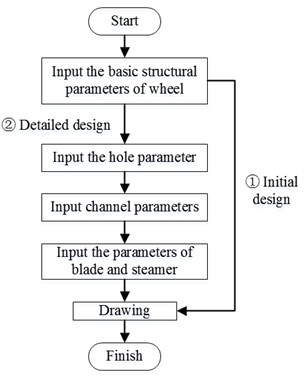
Fig. 2The diagram of the parameter used in design
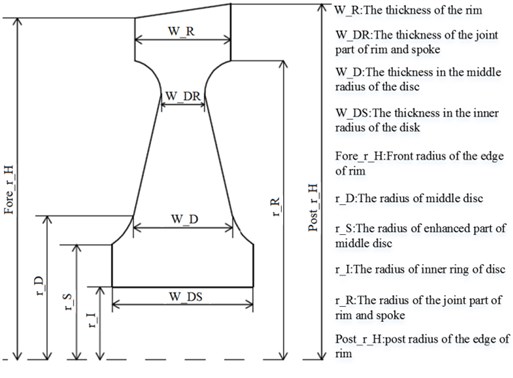
2.2. The parameters used in structural parameterization of disc
The structural parameters of disc were shown in Fig. 2. Table 1 showed all parameters used in parametric design.
Table 1The details of parameters used in design
Parameter | Description of parameter | Parameter | Description of parameter |
Fore(Post)_r_H | Front (Back) radius of the outer edge | W_DS | The thickness in the inner radius of the disk |
Fore(Post)_r_R | Front (Back) radius of the edge of the plate and the disk | N | Number of holes |
Fore(Post)_r_D | Front (Back) radius of the middle of the disk | Rr | Radius of the hole |
Fore(Post)_r_S | Front (Back) radius of the reinforced part of the middle part of the disk | Dr | Distance from the center of the hole to the axis of symmetry |
Fore(Post)_r_I | Front radius of the inner ring of the disk | SN | Number of gutters |
W_R | The thickness of the rim | SDr | Distance from the center of the gutter to the axis of symmetry |
W_DR | The thickness of the joint part of rim and spoke | Aglx(y)z | The angle between the gutter and the Z axis in the X(Y)Z plane |
W_D | The thickness in the middle radius of the disc | Height | The height of Blade |
2.3. The quick design of engine disc
The VB.net program consists of four modules: FanPan used for the disc design module, Holeclass for the hole design module, SunCaoClass for the gutter design module, and BladeClass for the rotor blade design. Among them, Holeclass, SunCaoClass and BladeClass were sub-modules of FanPan and the drawing results were shown in Fig. 3.
Fig. 3The structure designed by parametric software
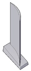
a) Blade
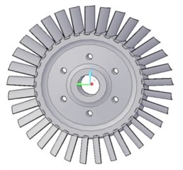
b) Disc
3. Structural optimization of disc
3.1. The process of optimization
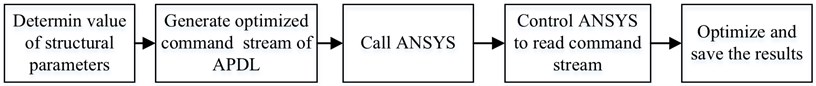
The parameterized model of the disc was used for optimization, and the optimized part was jointly completed by MATLAB and APDL language. The function of MATLAB language was to use parametric structural model, generated optimized command stream, to call ANSYS and controlled it to read optimized command stream file; APDL was used to read command stream file and control optimization and obtain optimized structural model. The optimal design flow was shown in Fig. 4.
As in optimal program in MATLAB, firstly, it created the initial population, set the generation counter and calculated the objective function value of the initial population, then the program started the process of iteration, assigned the fitness value, selected the population, got on reorganization, mutation and calculated the target value. The program also set the performance tracking of genetic algorithm.
Fig. 4The process of structural optimization
3.2. The analysis model used in optimization
The weight and strength of the disc were considered at the same time in optimal design, which means it belongs to a multi-objectives optimization problem.
The optimized mathematical model expression was expressed as:
where the denoted the strength and represent the weight of the disc; is objective function; is inequality constraints including stress and strain constraints; express the minimum while the denoted the maximum of the th variable; and are the weighting coefficients of the two target ( and ).
Before weighting, each target needs to be regularized to eliminate the difference in the order of magnitude. It is usually taken as , and , .
It is found that the unreasonable regularization method would strengthen or weaken a certain target inadvertently in practice, which leads to the weighting coefficient cannot accurately reflect the importance of the target, and finally the optimal result will be deviated from expectations. A better regularization method should convert both the weight and strength target values into dimensionless values in the range of 0-1 using the Eq. (3):
where and were the maximum values of the two targets of strength and weight, while and were the minimum values in the entire optimized region; the strength and the weight minimum are taken based on the strength limit and the given safety margin; the weight and the strength maximum are obtained at the geometric constraint boundary conditions, and denoted regularized target, then the Eq. (1) should be written as:
3.3. The range of variables used in design
It can be seen that there were 14 design parameters of the disc according to Fig. 2. In order to optimize the disc model and improve computational efficiency, the through holes, the gutters and the blade roots are not considered here. Aerodynamic performance was ensured by simplifying the blade root and gutter structure. The geometry at the rim cannot be used as a design variable because of the optimization of the hoe and the gutter needed to consider the contact problem, it needs to be optimized separately. In order to reduce the number of design variables and improve the efficiency of optimization, it was considered that the spoke and hub of the disc are mirror-symmetrical structures. Finally, there were five design variables of the disc optimization, which were the radius of the middle portion of the disk (RD), the radius of the reinforcing portion of the middle portion of the disk (RS), the radius of the inner ring of the disk (RI), the thickness of the intermediate radius of the disk (WD), and the thickness of the inner radius of the disk (WDS). The optimization of the disc is based on the size of the established disc model initially and the design variable range changed with the running of the program, scope files of variables could be generated by software with the changing of the model. The program for quick design of engine disc could generate disc model according to the changed parameter in time. The following relationships should be satisfied for the five design variables:
(1) The initial value of the radius of the inner ring of the disk < RD < The initial value of the radius of the joint portion edge between the plate and disk;
(2) The initial value of the radius of the inner ring of the disk < RS < The initial value of the radius of the joint portion edge between the plate and disk;
(3) The initial value of the radius of the inner ring of the disk < RI < The initial value of the radius of the joint portion edge between the plate and disk;
(4) 2 mm < WD < Initial thickness of the inner radius of the disk;
(5) 2 mm < WDS < Initial thickness of the inner radius of the disk.
Among them, ‘2 mm’ is the lower limit of the thickness in this research, which can be modified according to the actual engineering conditions.
3.4. Constraint conditions of optimization
The following were optimal constraints:
(1) Stress constraints:
where represented the maximum stress calculated for the disc; is the allowable stress of the disc.
(2) Geometric boundary constraints:
3.5. The results of optimization
The generations of optimization was set as 150, The initial values of the parameters of the disc model was listed in Table 2. The range of the design variables was determined according to the initial values and geometric constraints of the model. Material parameters and applied load parameters were required during optimization. Material parameters included material density, elastic modulus, Poisson's ratio, maximum allowed stress, and load parameters included the distance between blade’s centroid and the center of disc, the speed of disc and the generations of optimization. The mass of blades was converted into a centrifugal force and loaded on the rim when the strength calculation was ran, and the axial and circumferential displacement constraints were added to the rim of the front surface of the disc center. The material parameters and applied loads were shown in Table 3 and Table 4.
Table 2Initial value of the parameter
Parameter name | Initial value of the parameter (mm) | Parameter name | Initial value of the parameter (mm) |
Fore_r_H | 120 | Post_r_S | 40 |
Post_r_H | 125 | Fore_r_I | 25 |
Fore_r_R | 105 | Post_r_I | 25 |
Post_r_R | 105 | W_R | 34 |
Fore_r_D | 50 | W_DR | 10 |
Post_r_D | 50 | W_D | 38 |
Fore_r_S | 40 | W_DS | 50 |
Table 3Material performance parameters
Material name | Material density | Elastic modulus | Poisson’s ratio | Allowable stress |
1Cr11Ni2W2MoV | 7800 kg/m3 | 1.96e11 | 0.3 | 450 MPa |
Table 4Load parameter
Number of blades | Weight of single blade | The distance from the center of the blade to the center of the disc | Disc speed |
26 | 0.5 kg | 150 mm | 1000 rad/s |
Table 5The results of structural optimization
The value of parameter (mm) | The generations of convergence | Objective value function (Kg) | ||||
RI | RS | RD | WD | WDS | ||
81.389 | 89.212 | 93.308 | 2.003 | 33.611 | 52 | 5.75 |
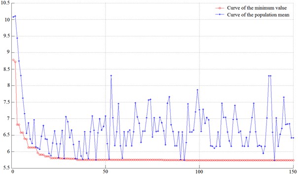
The optimal results were shown in Table 5 and Fig. 5. It could be seen that the target value was converged around 50 generations from the target curve of optimization, and the weight of the disc was reduced from 8.7 kg to 5.75 kg while the strength met the allowable conditions. The weight of disc reduction was nearly 3 kg accounting for 34.48 % of the original weight.
Fig. 5The target curve of optimization
4. Conclusions
The parametric design method and structural optimization technology of aero-engine component structure were studied in this paper. Following were the conclusions:
1) The parametric design software for aero-engine disc was designed using VB.net language to develop AutoCAD.
2) The program of structural optimization was designed based on the MATLAB language to call the ANSYS Apdl statement.
3) The weight of the disc was reduced by 34.48 % after optimizing while the strength met the allowable conditions. It can be seen that the weight reduction effect was very considerable.
References
-
Wang K., Liu Ch, Cai T. M. Optimization design method of solid rocket motor structure based on database technology. Solid Rocket Technology, Vol. 33, Issue 2, 2010, p. 171-175.
-
Wu F. Z., Liu J. F., Chen J. M. Application of AutoCAD VB development technology in parametric design of generator sets. Mobile Power and Vehicle, Vol. 4, 2000, p. 17-20.
-
Song Y. W., Xi P. Parametric design of turbine blades based on feature modeling technology. Journal of Beijing Aerospace University, Vol. 30, Issue 4, 2004, p. 321-324.
-
Zhang Ch J., Li X. H., Yang J. G. Research on parametric design of V-Type Engine. Mechanical Design and Research, Vol. 22, Issue 4, 2006, p. 98-101.
-
Tang Y. B., Luo G. H., Zheng K. Y. Parametric design technology of airborne engine. Aircraft Engine, Vol. 30, Issue 2, 2004, p. 10-13.
-
Luan Y. X., Luo G. H. Analysis of contact pressure between boltless baffle and blade. Journal of Aeronautical Power, Vol. 22, Issue 9, 2007, p. 1550-1553.
-
Bai Ch Y., Zhong J. P. Optimization design of boom structure based on Hypermesh. Lifting and Transport Machinery, Vol. 4, 2012, p. 36-38.
About this article

