Abstract
This paper discusses how to improve the machining precision in the turning of slender shaft. The main cause of dimensional error in slender shaft machining is analyzed by establishing dimensional error model and using genetic algorithm to optimize cutting parameter selection. Based on this, the proportional-integral-differential control error compensation is proposed to reduce the error in the turning process of slender shaft. Through the simulation experiment, the machining size error of slender shaft under different cutting parameters is obtained. It is found that the increase of back blowing and feed rate will aggravate the dimensional error, while the increase of CS will reduce the dimensional error. The error after the proportional-integral-differential control error compensation is much smaller than that without the error compensation. The experimental results show that the method is reliable in reducing the errors in the turning of slender shaft, and can realize the machining mode with higher precision and efficiency. This is of great significance to the development of machinery manufacturing industry.
1. Introduction
As the boost of science and technology, the machinery industry, as an important basic industry of the national economy, possesses an influence on promoting economic growth that cannot be ignored [1-2]. However, the precision of the machine itself and the machining precision of the parts are inseparable, and the latter largely affects the former. Therefore, enhancing China’s machinery manufacturing industry is a far-reaching task for every machinery researcher [3-4]. As an essential part of mechanical structure (MCS), such as transmission and connection, the problem of machining precision of slender shafts has been plaguing the machinery industry. At present, scholars at home and abroad have carried out a series of researches to reduce the errors of bending deformation of slender shaft turning, mainly in the aspects of process method, fixture, operation method, tool and cutting amount selection [5-6]. However, with the boost of science and technology today, the traditional methods cannot meet the current requirements of machining precision in the mechanical industry. Therefore, it is particularly important to explore new machining methods. A dimensional error (DE) model is developed and a genetic algorithm (GA) is utilized for optimizing the selection of cutting parameters for slender shafts. Then, finite element (FE) analysis is applied to verify the main influencing factors in the model, and the error compensation technique is used to compensate the slender shaft turning machining to meet the precision requirements in actual machining. The study will explore the error compensation technology when machining slender shafts. This is to achieve a more exact and efficient machining model in the machinery manufacturing industry. This has taken an important step in China's manufacturing industry.
The study is divided into four parts. The first part compares and summarizes the relevant domestic and foreign research; the second part proposes the use of GA for optimizing the selection of slender axis cutting parameters; through the proportional-integral-differential (PID) control for dimensional in the third part, the PID control error compensation is verified through simulation experiments; in the fourth part, the research content is summarized.
The machining precision of mechanical parts, which are an essential part of MCS such as drives and connections, has been plaguing the machinery industry. Different techniques and methods, including slow tool servo (STS) turning, mechanical analysis model, machine learning model, inverse identification method and probe measurement, are used in the above work to achieve higher machining precision and increase the productivity of the machine tool. Although these methods have achieved certain results in improving machining precision and increasing machine tool productivity, there are still some shortcomings. For example, the STS turning method may face difficulties in dealing with complex shape parts. The mechanical analysis model may not fully consider all the influencing factors in the actual machining process, and the probe measurement method may be affected by measurement errors (MEs).
Firstly, the contribution of GA is to improve the precision. By selecting the best cutting parameters adaptively, GA can effectively reduce the DE in the process of slender shaft machining, thus improving the machining precision. Secondly, it can improve the efficiency. GA can get a satisfactory solution in a short time, which is of great significance for improving the production efficiency and shortening the time to market. Finally, it provides a new research method. The introduction of GA also provides a new research method for the cutting parameter optimization of slender shaft, and provides a reference for the subsequent research. The reason why GA is chosen is because of the complexity of the problem, the cutting parameter optimization problem involves multiple parameters and objectives, which is a typical multi-objective optimization problem. GA is suitable to deal with this kind of problem, while some other algorithms may not be able to deal with it effectively. Second, because of its global search ability, GA has a good global search ability and can find the global optimal solution in a large-scale search space. Other algorithms may easily fall into local optimality. GA has been widely used in a variety of optimization problems. The algorithm is relatively mature, and there are many ready-made tools can be used, which may also be a reason for choosing GA.
2. Related works
The machining precision of mechanical parts, which are an essential part of MCS such as drives and connections, has been plaguing the machinery industry. Nagayama K et al. proposed a new process flow for STS turning, which integrates analysis, simulation and compensation of tool trajectory error, tool alignment error and dynamic. The results showed that the proposed error factor could be used to achieve nanometer-level shape accuracy. The outcomes denoted that the shape error could be reduced to 8 nm P-V and the surface roughness to 1 nm Sa using the proposed error compensation, which proved the effectiveness. [7]. Straka Ľ A method has been proposed by others to solve the geometric accuracy deviation of the machined surface (MS) in the electric discharge wire cutting. By determining the impact of process parameters and workpiece materials on the geometric deviation of the MS, a mathematical model and simulation software algorithm were proposed, which could predict the necessary process parameter settings to ensure that the geometric accuracy requirements were met [8]. Soleimanimehr H performed a vibration analysis of ultrasonic vibration-assisted turning. The findings indicated that when the workpiece rigidity or cutting ratio was stable, the diameter error from vibration of the vibrating turning tool was negligible; while in the case of considering flexible workpieces, the cutting ratio tended to increase and the workpiece diameter error was about twice that of conventional turning [9]. Etxebarria A et al. proposed a hardware-in-the-loop chattering simulator improvement that could realistically reproduce the regenerative chattering phenomenon on a specially designed MCS and correct for the effect of the delay introduced by the equipment used on the vibration. In addition, the function of a new controller in view of the elimination of the entire variable cutting force was analyzed [10].
Boca M. et al. proposed a method for measuring machining errors, including elastic deflection, radial deviation, and roughness evaluation. These devices could be easily connected to the lathe and provided signals that can be converted into displacement. The obtained data would provide important results for compensating machining errors, and it was recommended to use this method in the field of cutting technology [11]. Zha J et al. presented an “evolutionary” method for improving the machining precision of surfaces by reducing small errors during the machining process, updating and improving key parameters, and ultimately achieving perfect application of the final product after a single development and manufacturing program. Experiments have shown that this method could improve surface precision and reduce errors by approximately 90 % [12]. Dutta S et al. analyzed the cutting in various terms for various combinations of turning parameters and compared the predicted data (PD) with the experimental data (ED). The outcomes denoted that the PD agreed with the ED and most of the observed variations were less than 12 %, proving the effectiveness of the inverse identification method [13]. Buhmann M. et al. used a one-dimensional probe to move through the machine axis for optically scanning the workpiece, introduced a method for integrating and positioning the probe, and performed relevant tests for identifying the effect of the probe positioning error on the measurement results. The ME influenced the gradient of the geometry to be measured, and the ME on the spindle axis influenced the shape deviation of the measurement [14].
Different techniques and methods, including STS turning, mechanical analysis model, machine learning model, inverse identification method and probe measurement, were used in the above work to achieve higher machining precision and increase the productivity of the machine tool. The study will analyze the main causes of DE in slender axis machining by establishing a DE model and using GAs for optimal selection of slender axis cutting parameters. And based on this, a PID error compensation will be proposed to reduce the errors generated during the slender axis turning.
In the summary of domestic and foreign related research, it was found that domestic research has made certain progress in STS turning, mechanical analysis model and other aspects, but there is relatively less research in machine learning model, inverse identification method and other aspects. Foreign research has in-depth discussions in these areas. This study will analyze the main causes of DE in slender axis machining by establishing a DE model and using GAs for optimal selection of slender axis cutting parameters. And based on this, a PID error compensation will be proposed to reduce the errors generated during the slender axis turning.
3. GA for part turning error correction design
The study establishes a DE model and uses GAs to optimize the selection of cutting parameters for slender shafts. Meanwhile, FE analysis is applied to verify the main influencing factors in the model, and the error compensation technique is used to compensate for the slender axis turning machining to meet the precision requirements in actual machining.
3.1. Optimal selection of CNC turning parameters for mechanical parts
The combined turning force can be decomposed into three mutually perpendicular forces, axial force , tangential force , and radial force . As the direction of the three forces is different, so the bending deformation error generated during the slender axis turning is also different. To study their impact on the slender axis turning, combined with the actual turning, the slender axis turning error model is established for establishing the impact of each force on the DE of the workpiece turning. The model of slender axis turning error is shown in Fig. 1.
The optimal selection of turning parameters for slender shafts of mechanical parts is of great importance in improving machining precision, productivity and reducing costs. In Fig. 1(b), the double dotted small circle represents the theoretical diameter of the slender shaft turning, the thin straight line small circle represents the actual turning size of the slender shaft, and the large circle represents the diameter before the slender shaft turning. Point represents the machining point, represents the back feed of the tool, , represent the center of the circle, and , respectively represent the yielding amount of the slender axis in the and directions during the turning process, that is, the bending deformation amount that occurs in both directions during the slender axis turning process. In triangle , , Eq. (1) can be obtained from theoretical analysis:
Fig. 1Decomposition of cutting force and turning error model
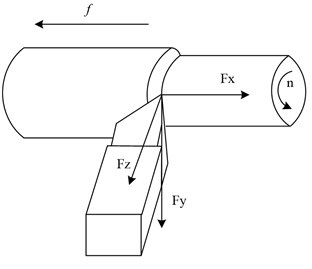
a) Cutting force decomposition
b) Error model for slender axis turning
The machining error of a slender shaft under the action of radial force is shown in Eq. (2):
The machining error of the slender axis under the action of tangential force is shown in Eq. (3):
By comparing Eq. (2) and (3), it can be seen that the machining error caused by is much greater than that caused by Uy; That is to say, the machining error caused by radial force during the turning process of slender shafts is much greater than that caused by tangential force . Therefore, it can be seen that radial force is the main factor causing bending deformation during the turning process of slender shafts.
Genetic algorithm can provide a framework with good applicability. When solving engineering problems, only existing patterns need to be analyzed and solved. Genetic algorithm can solve problems in most fields and has strong robustness. Genetic algorithm, as an optimization method, can be used to optimize cutting parameters for turning slender shafts, avoiding the drawbacks of traditional optimization methods that tend to converge to local optima when performing non-linear linear optimization.
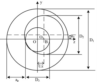
GAs can solve the computational complexity of nonlinear equations and avoid the drawback of easy convergence to locally optimal solutions. Compared with traditional optimization methods, GAs are characterized by intelligence, intrinsic parallelism, and ease of use. Its intrinsic parallelism and embedded parallelism make it highly computationally efficient [15-16]. The flow chart of GA optimization selection as a typical iterative solution is shown in Fig. 2.
Fig. 2GA process
GA is an efficient global search method whose basic operations include selection, crossover and mutation. It provides a highly applicable model for solving complex system optimization problems. GAs are robust and not limited to the scope of the problem being solved, and have an extremely wide range of applications.
To solve the difficult machinability of slender shafts of mechanical parts, it is crucial to perform the optimization of turning parameters. Turning parameter optimization aims to minimize the DE of the workpiece during the turning process by solving for the optimal cutting parameters under the constraints. Mechanical parts are usually machined using multiple tool passes to ensure machining quality and minimize DE. Although smaller cutting amounts can reduce DE, they can lead to long machining times and reduced productivity [17-18]. Therefore, to achieve a certain level of productivity in the turning of mechanical parts, it is essential for choosing the parameters with the shortest machining time as the optimization target. Assuming that the time used for the machining of mechanical parts with multiple tool walking turning is , the optimization objective function (OF) is expressed as in Eq. (4):
where, indicates the finishing time; means the time for one tool change; is the auxiliary time other than the tool change time, and denotes the tool life during finishing. In the case of a known part turning, the parameters and are known, so the minimum cutting time is a function of the finishing time and the tool life in finishing . After the rough machining of a mechanical part is completed, it needs to be finished, and the finishing time is expressed as in Eq. (5):
where, is the finishing feed of the machined part (mm/r); serves as the finishing feed speed of the machined part (m/min); is the DE, and is the backlash of the tool. In the optimization, it is often necessary to add constraints to ensure that the workpiece satisfies the machining needs during turning. The study takes into account the actual turning process to constrain the machining parameters as in Eq. (6):
In the actual machining process, the DE of the machined workpiece should be less than the given maximum DE. According to the size of the DE of the actual turning process and the construction of the dimensional model, the maximum DE is predicted to be approximately 10 μm, so the cutting dosage should satisfy the condition as in Eq. (7):
The surface roughness of a mechanical part is an important indicator and the optimized result should meet the specified standard of the surface roughness of the part, so the feed during the finishing process should satisfy Eq. (8):
where, is the allowable surface roughness for machining (μm) and serves as the radius of the tool tip arc (mm). In view of the characteristics of mechanical parts turning, the cutting amount is constrained in the optimization as in Eq. (9):
The problem of optimizing the cutting parameters of mechanical parts is actually solving the OF under various constraints to finally obtain the cutting parameters that meet the requirements. With the machining parameters as the constraint variables and the minimum machining time as the OF, the minimum value of the OF under the above constraints is solved as in Eq. (10):
3.2. Error compensation correction strategy design
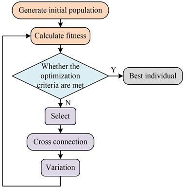
The machining quality of mechanical parts is closely relevant to the type, and the machining quality of slender shafts and common shafts are subject to different causes of force deformation. Increasing the machine tool stiffness can effectively reduce the machining DE of common shafts, but for slender shafts, it is difficult to mitigate the DE caused by bending deformation by increasing the machine tool stiffness alone. Therefore, a new PID machining precision control model is proposed to compensate the DE generated during the machining of slender shafts without changing the original accuracy of the machine tool. The PID error control system compensation method can measure certain state parameters in real time, compare the target parameters, and adjust the input parameters in time to keep the cutting process in the best condition, thus improving the machining accuracy. It has the advantages of easy operation, low cost and high feasibility, which can meet the machining requirements well [19]. The PID control principle is showcased in Fig. 3.
Under the action of PID controller, the error signal is subjected to PID operations respectively, and the sum of the three action components is output to the controlled object as the control signal. The mathematical model of PID control is shown in Eq. (11):
where, serves as the output signal of the PID controller; is the integration time constant; is the proportionality factor; is the differential time constant. The system error signal is calculated as shown in Eq. (12):
where, is the given input signal of the system and is the controlled quantity of the system. The transfer function model of the PID controller is shown in Eq. (13):
where, the integration coefficient , and the differentiation coefficient are expressed. In MATLAB, the PID is provided in a package form and its internal form is shown in Fig. 4.
Fig. 3Principles of PID control system
Fig. 4PID controller
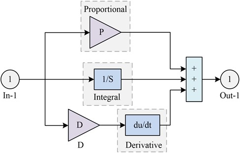
The PID control system includes three links: proportional, integral and differential. Among them, the proportional link mainly improves the regulation accuracy and response speed, and by reflecting the error signal , the controller generates the control effect to reduce the size of the error. The integral link mainly eliminates the static error and improves the stability, while the differential link describes the error signal change law. By analyzing the error signal in advance implantation correction signal, it eliminates the static error and speeds up the action response rate of the system. These three links work together to enable the PID control system to effectively control the system output and achieve the desired control objectives. For Eq. (10), when , then there is ; when , then there is Eq. (14):
In this case it is a proportional differential regulator, which is equivalent to an overcorrection if it is used as a corrector; when , then Eq. (15) exists:
In this case, it is a PID regulator, and if it is used as a corrector, it is equivalent to a hysteresis regulator. The discretized PID algorithm is shown in Eq. (16):
where, and ; is the sampling time; denotes the sampling sequence quantity, and ; is the error signal at the time. Eq. (16) is a position-based algorithm, and its corresponding PID incremental algorithm is shown in Eq. (17):
Closed-loop control is an important concept in control theory, which is mainly through the feedback mechanism, the disparity in the output quantity and the given quantity as a signal to achieve the input end of the re-control, for achieving the desired goal. In CNC machine tools, closed-loop control can reduce system error and improve machining precision by providing differential feedback on the deviation of the actual size of the machined workpiece from the theoretical value after actual measurement, to control the movement of the tool in the next step.
The size setting value is the ideal final size of the workpiece in the actual turning, i.e. the expected value; the actual machining size is the actual value obtained after machining, i.e. the output value. The deviation of the system is the disparity in the output value and the expected value. This deviation can be analyzed and processed by the control system as a feedback quantity, and then the closed-loop manufacturing system can be adjusted again to improve the workpiece and meet the requirements of the turning process. Through the feedback mechanism, the deviation of the manufacturing system is automatically adjusted to achieve the improvement of workpiece machining precision [20].
The PID error control model is a simple and effective control method to reduce DE by controlling the DE and, in turn, acting on the machining system to make timely adjustments to the turning process. To achieve this purpose, an online detection device needs to be added to the whole system to be able to detect the error and make feedback adjustment in time. The PID control model for the turning of mechanical parts is shown in Fig. 5.
In Fig. 5, indicates the machining number; expresses the theoretical diameter of the given mechanical part; refers to the actual measured diameter after turning; indicates the actual turned size of the machine after adjustment; stands for the basic error, and means the error compensation value. According to the closed-loop control principle, the PID error model of turning accuracy of mechanical parts is constructed as Eq. (18):
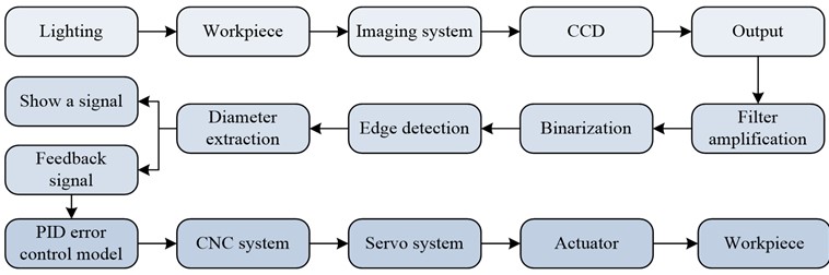
The inspection system designed in the study uses CCD inspection system to detect the workpiece diameter in real time during the turning process and transmits the detection results to the PID error control model for slender axis turning in time. Through the analysis and calculation of the PID error control model, the error size is fed back to the CNC system, which controls the next turning process of the slender axis through the cutting compensation of the tool. This automatic control method can effectively improve machining efficiency (MEY) and precision, and can ensure the stability of product quality. The principle of DE detection of mechanical parts is shown in Fig. 6.
Fig. 5Structure of closed-loop manufacturing system and PID control model for turning machining
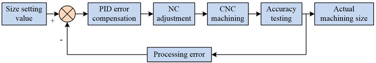
a) Comparison structure of closed-loop manufacturing system
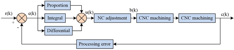
b) PID control model for turning machining
Fig. 6Principle of measuring the size error of slender shafts
3.3. GA-based error correction experimental analysis of CNC turning machining of mechanical parts
This study optimizes and solves the turning parameters of slender shafts in MATLAB. The experiment used a slender axis with a diameter of = 40 mm and a length of = 1000 mm as the research object, and solved its cutting parameters. The quality standards for workpiece processing are as follows. Surface roughness = 3.2 μm, dimensional error = 0.02 mm. During the turning process of slender shafts, the chuck tip is used for clamping, which is a clamping method of one clamp and one top. The workpiece material is 45 steel, and the cutting tool is made of hard alloy indexable turning tools. Then determine other cutting parameters required during the optimization process. The front angle of the tool is 15°, the rear foot is 6°, the main deviation angle is 90°, the secondary deviation angle is 15°, the blade inclination angle is 0°, and the tip arc radius is 0.4mm. The constraints are as follows. = 30 m/min, = 80 m/min, = 0.1 mm/r, = 0.3 mm/r, = 0.2 mm, = 1 mm, = 80 m/min, = 0.1 mm/r, = 0.25 mm, = 24 min.
After the optimization is completed, the obtained cutting parameters are used to cut the slender shaft. From the results, it can be seen that the machining process of the slender shaft is stable and meets the requirements of dimensional error and surface roughness. The surface roughness after machining is 1.6 pm, the size error fluctuates around 0.1 mm, and the finishing time is 24 minutes. The cutting parameter optimization method studied and designed can not only meet the quality requirements of turning machining, but also improve cutting efficiency.
The study used the single-factor method for analyzing the effect of cutting parameters on the DE of turning mechanical parts by setting different back draft, cutting speed (CS) and feed for multiple simulations. The simulation experiments were carried out with a chucked flexible center clamping method and a slender shaft which was discrete into 10 parts with 100 nodes. The FE method was utilized for studying the effect of various back draft on the DE of turning of slender shafts and to explore ways to improve the MEY and precision. The scheme of setting the effect of back draft on the DE of the slender shaft is shown in Table 1.
Table 1Setting of back cutting amount
Number | Depth of cut (mm) | CS (m/min) | Feed rate (mm/r) | Radial force (N) |
1 | 0.10 | 40 | 0. 10 | 49.84 |
2 | 0.14 | 40 | 0. 10 | 67.18 |
3 | 0.18 | 40 | 0. 10 | 84.62 |
4 | 0.20 | 40 | 0. 10 | 101.34 |
5 | 0.26 | 40 | 0. 10 | 117.82 |
6 | 0.30 | 40 | 0. 10 | 133.96 |
7 | 0.34 | 40 | 0. 10 | 149.97 |
8 | 0.38 | 40 | 0. 10 | 165.74 |
The study examined the relationship between CS and DE during machining of the workpiece. Under the assumption of constant back draft and feed, different CS were varied to analyze their effects on DE in machining of slender shafts. The CS setting scheme is illustrated in Table 2.
Table 2CS setting
Number | Depth of cut (mm) | CS (m/min) | Feed rate (mm/r) | Radial force (N) |
1 | 0.20 | 30 | 0.10 | 11.09 |
2 | 0.20 | 40 | 0.10 | 10.18 |
3 | 0.20 | 50 | 0.10 | 9.52 |
4 | 0.20 | 60 | 0.10 | 9.01 |
5 | 0.20 | 70 | 0.10 | 8.62 |
6 | 0.20 | 80 | 0.10 | 8.24 |
7 | 0.20 | 90 | 0.10 | 7.95 |
8 | 0.20 | 100 | 0.10 | 7.24 |
For ensuring the accuracy of FE simulation analysis, the study chose Beam189 unit for the analysis of the slender shaft itself. The simulation model was statically simulated by ANSYS software, and the displacement constraints in and directions at the right end of the workpiece were used as boundary conditions, and all degrees of freedom at the left end of the workpiece were restricted and forces were applied at node 71. The parameters of the slender shaft were length 1 = 1000 mm, diameter 50 mm, material 45 steel, density 7.8 g/cm3, modulus of elasticity 2.1×10⁶Pa, Poisson’s ratio 0.3. The effect of different back draft on the DE of the slender shaft turning is shown in Fig. 7.
From Fig. 7, the DE showed a trend of growing and then diminishing with the cutting point position’s increase. When the cutting point position was 500 mm, the DE of slender shaft machining with the back draft of 0.10 mm, 0.18 mm, 0.26 mm and 0.34 mm were 15.4×10⁻⁶ m, 25.7×10⁻⁶ m, 36.8×10⁻⁶ m and 47.1×10⁻⁶ m, respectively. In slender shaft turning, the DE increased with the increase of back draft, and according to the relationship diagram, the maximum error point was located in the middle part of the shaft against the flexible top. The back draft had a great influence on the error, so it should be chosen carefully under the premise of ensuring the MEY and precision. The FE software was used for carrying out FE simulation analysis on the eight sets of data in Table 2, and the influence of different CS on the DE of slender shaft turning was obtained. The results are shown in Fig. 8.
Fig. 7The influence of different back cut on the DE of slender axis turning
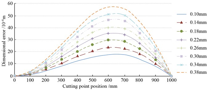
Fig. 8The influence of different CS on the DE of slender axis turning
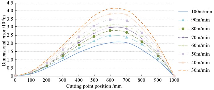
From Fig. 8, the DE showed a trend of growing and then diminishing with the cutting point position’s increase. When the cutting point position was 500 mm, the DE of slender shaft machining at CS of 30 m/min, 50 m/min, 70 m/min and 90 m/min were 3.7×10⁻⁶ m, 3.0×10⁻⁶ m, 2.6×10⁻⁶ m and 2.1×10⁻⁶ m, respectively. By analyzing the relationship between CS and DE, the larger the CS, the smaller the DE of slender shaft. This was because the CS grew, the radial force on the workpiece decreased, the deformation of the workpiece also decreased, and thus the DE decreased. When choosing the CS, the MEY and precision should be considered, and choosing a higher CS could enhance the MEY. The study conducted experiments on the size of the feed, and the effect of different feeds on the DE of slender shaft turning was derived. The results are shown in Fig. 9.
From Fig. 9, the DE denoted a trend of growing and then diminishing with the cutting point position’s increased. When the cutting point position was 500 mm, the DE of slender shaft machining at feeds of 0.05 mm/r, 0.15 mm/r, 0.25 mm/r and 0.35 mm/r were 19.9×10⁻⁶ m, 35.1×10⁻⁶ m, 48.8×10⁻⁶ m and 60.7×10⁻⁶ m, respectively. The increase of feed would aggravate the DE when turning slender shafts. A growth in feed led to a growth in cutting layer thickness and cutting area, with a corresponding increase in cutting forces. However, the growth in cutting force increased the bending deformation of the workpiece, which eventually led to larger DE.
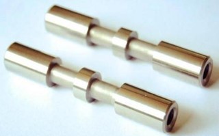
The study found that the optimized selection, although improving machining accuracy, was not effective enough through the analysis of slender axis turning parameters. Therefore, a PID control model was considered to improve the machining precision of turning, and experimental verification was conducted. FANUC-Oi CNC lathe, laser CCD controller and other equipment were used for the experiment. The cutting parameters were 80 m/min, 0, 1 mm/r, 0.25 mm; the material was 45 steel, and the ideal diameter of the workpiece was 25 mm. The values of the adjustment factors of the PID control model were finally determined by reviewing the related literature, = 1.2, = 0.05, = 0.05. The slender shaft of the machined part is shown in Fig. 10.
Fig. 9The influence of different feed rates on the DE of slender axis turning
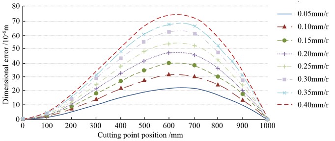
Fig. 10Machine element slender shaft
The study was conducted to measure the DE after ordinary turning machining of slender shafts and PID error control model error compensation turning machining respectively, and the outcomes are demonstrated in Fig. 11.
Fig. 11Comparison of size errors
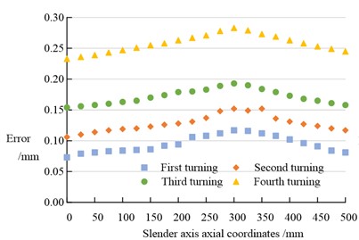
a) Error free compensation for turning dimension error
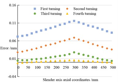
b) PID error compensation for turning dimension error
In Fig. 11, with and without error compensation, the error increased and then decreased as the axial coordinate of the slender axis increased. In Fig. 11(a), when the axial coordinate of the slender axis was 250 mm, the errors of the four turning operations were 0.108 mm, 0.137 mm, 0.183 mm and 0.271 mm respectively. In Fig. 11(b), when the axial coordinate of the slender axis was 250 mm, the errors of the four turning operations were 0.108 mm, 0.061 mm, 0.020 mm and 0.005 mm respectively. By comparison, the error under PID error compensation was much smaller than that under no error compensation. The DE of slender axis in turning machining showed the characteristics of small at both ends and large in the middle, and gradually accumulated with the increase of turning machining times, resulting in the reduction of machining accuracy. The machining accuracy PID error control model could reduce the error and improve the machining accuracy through PID compensation. The experimental results indicated that under the PID-compensated turning machining conditions, the DE of the slender shaft still showed the characteristics of small at both ends and large in the middle, but the maximum DE value was significantly improved and finally reached 0. 005 mm, which fully met the machining precision requirements in actual production.
In this study, parameters in CNC turning were analyzed in detail to explore their influence on DEs. The findings denoted that back grass, CS and feed rate all had significant effects on DE. With the increase of the back cut, the DE also increased. This might be due to an increase in the back cut leading to an increase in the cutting force, resulting in a change in the shape of the workpiece. To ensure maximum economic benefits and accuracy, it was especially important to choose the right back cut. An increase in CS would lead to a decrease in DEs. This might be due to the increase in CS resulting in a reduction in radial force on the workpiece, thereby reducing the deformation of the workpiece and DEs. When choosing the CS, it was necessary to take into account the maximum economic benefits and precision, and choosing a higher CS could improve the maximum economic benefits. An increase in the feed would lead to an increase in the DE. This might be due to the increase in the feed rate leading to an increase in the thickness of the cutting layer and the cutting area, which in turn led to an increase in the cutting force. However, the increase of cutting force would increase the bending deformation of the workpiece, and eventually led to the increase of DE. However, the study also found that by optimizing the selection parameters, although the machining accuracy could be improved, the effect was not enough. Therefore, the PID control model was considered to improve the machining precision of the turning, and the experimental verification was carried out. The results showed that the dimensionality error of the turning process using PID error compensation model was obviously smaller than that without error compensation. This indicated that PID error control model could reduce error and improve machining precision by PID compensation. Overall, this study provided an effective method to optimize the parameters of CNC turning machining to reduce DEs and improve machining precision. This had important guiding significance for precision machining in actual production.
The DE model was established, which was a theoretical innovation. The DE in slender shaft machining was analyzed by mathematical model, which provided a theoretical basis for optimizing cutting parameters. GA was used to optimize the selection of cutting parameters: this was a method innovation. Through the intelligent optimization of GA, the optimal selection of cutting parameters was realized, which had an important role in improving the machining precision. The PID control error compensation was proposed in this paper. It was a technical innovation, which could effectively reduce the error in the turning process of slender shaft and achieve higher machining precision. The effectiveness of the method was verified by simulation experiments, which was an empirical innovation. In general, this paper proposed a new method to improve the precision of slender shaft turning through theoretical modeling, intelligent optimization, technological innovation and empirical verification, which was of great significance to the development of machinery manufacturing industry.
4. Conclusions
A size error model was established and genetic algorithm was used to optimize the selection of cutting parameters for slender shafts. At the same time, finite element analysis was used to verify the main influencing factors in the model, and error compensation technology was used to compensate for the machining of slender shafts, meeting the accuracy requirements in actual machining. Through simulation experiments, it can be concluded that as the back feed increases in slender shaft turning, the size error also increases. The higher the cutting speed, the smaller the dimensional error in turning slender shafts. An increase in feed rate will exacerbate dimensional errors. When the axial coordinate of the slender axis is 250 mm without error compensation, the errors of the four turning processes are 0.108 mm, 0.137 mm, 0.183 mm, and 0.271 mm, respectively. The errors of the four turning processes under PID error compensation are 0.108 mm, 0.061 mm, 0.020 mm, and 0.005 mm, respectively. The error under PID error compensation is much smaller than the error without error compensation. The results indicate that the proposed method is effective and reliable in reducing errors in slender shaft turning, and can achieve higher precision and efficiency machining modes in the mechanical manufacturing industry.
Genetic algorithm, as an optimization method, can be used to optimize cutting parameters for turning slender shafts, avoiding the drawbacks of traditional optimization methods that tend to converge to local optima when performing non-linear linear optimization. This study successfully established a size error model in slender shaft machining, which is an innovative attempt to accurately predict and control the machining error of slender shafts. This article uses genetic algorithm to optimize the selection of cutting parameters for slender shafts. This method is more scientific than traditional parameter selection methods and can greatly improve the accuracy and efficiency of machining.
The magnitude of the radial force used in the research institute is calculated by the empirical formula of radial force cutting, and there are some errors in it. In ideal situations, other more accurate methods should be used to obtain the value of the radial force. In addition, the optimization of cutting parameters is studied using the single objective function optimization method of genetic algorithm. To further reduce errors, the multi-objective function optimization method can be used, which can make the result error smaller and more conducive to improving the machining accuracy of slender shafts. In the future work direction, the error model in the research can be further optimized to adapt to more processing conditions and materials. In addition, the finite element analysis method can be further expanded to study more influencing factors and mechanical behavior.
References
-
P. Zmarzły, “Technological heredity of the turning process,” Tehnicki vjesnik – Technical Gazette, Vol. 27, No. 4, pp. 1194–1203, Aug. 2020, https://doi.org/10.17559/tv-20190425150325
-
Mohsen Soori, “Virtual machining systems for CNC milling and turning machine tools: a review,” International Journal of Engineering and Future Technology, Vol. 18, No. 1, pp. 56–104, Jan. 2020.
-
D. Božanić, A. Milić, D. Tešić, W. Salabun, and D. Pamučar, “D numbers – fucom – fuzzy rafsi model for selecting the group of construction machines for enabling mobility,” Facta Universitatis, Series: Mechanical Engineering, Vol. 19, No. 3, pp. 447–471, Oct. 2021, https://doi.org/10.22190/fume210318047b
-
B. Toubhans, P. Lorong, F. Viprey, G. Fromentin, and H. Karaouni, “A versatile approach, considering tool wear, to simulate undercut error when turning thin-walled workpieces,” The International Journal of Advanced Manufacturing Technology, Vol. 115, No. 5, pp. 1919–1929, May 2021, https://doi.org/10.1007/s00170-021-07243-8
-
Z. Geng, Z. Tong, and X. Jiang, “Review of geometric error measurement and compensation techniques of ultra-precision machine tools,” Light: Advanced Manufacturing, Vol. 2, No. 2, pp. 211–227, 2021, https://doi.org/10.37188/lam.2021.014
-
J. Peterka, W. T. de Silva, R. Straka, T. Vopát, J. Hrbál, and M. Kritikos, “Analysis of form error and roughness of hardened steel workpieces internally turned with different tools in long overhangs,” Research Papers Faculty of Materials Science and Technology Slovak University of Technology, Vol. 30, No. 50, pp. 21–29, Jun. 2022, https://doi.org/10.2478/rput-2022-0003
-
K. Nagayama and J. Yan, “Deterministic error compensation for slow tool servo-driven diamond turning of freeform surface with nanometric form accuracy,” Journal of Manufacturing Processes, Vol. 64, pp. 45–57, Apr. 2021, https://doi.org/10.1016/j.jmapro.2021.01.015
-
Straka, J. Piteľ, and I. Čorný, “Influence of the main technological parameters and material properties of the workpiece on the geometrical accuracy of the machined surface at wedm,” The International Journal of Advanced Manufacturing Technology, Vol. 115, No. 9-10, pp. 3065–3087, Aug. 2021, https://doi.org/10.1007/s00170-021-07313-x
-
H. Soleimanimehr, “Analysis of the cutting ratio and investigating its influence on the workpiece’s diametrical error in ultrasonic-vibration assisted turning,” Proceedings of the Institution of Mechanical Engineers, Part B: Journal of Engineering Manufacture, Vol. 235, No. 4, pp. 640–649, 2021, https://doi.org/10.1177/095440542096817
-
A. Etxebarria, R. Barcena, and I. Mancisidor, “Active control of regenerative chatter in turning by compensating the variable cutting force,” IEEE Access, Vol. 8, No. 99, pp. 224006–224019, 2020, https://doi.org/10.1109/access.2020.3043975
-
M. Boca and M. Horodincă, “The possibilities to use a signal for describing the elastic deflection behaviour of a workpiece processed by turning,” International Journal of Modern Manufacturing Technologies, Vol. 12, No. 2, pp. 17–22, 2020.
-
J. Zha, N. Villarrazo, G. Martínez de Pisson, Y. Li, H. Zhang, and L. N. López de Lacalle, “An accuracy evolution method applied to five-axis machining of curved surfaces,” The International Journal of Advanced Manufacturing Technology, Vol. 125, No. 7-8, pp. 3475–3487, Apr. 2023, https://doi.org/10.1007/s00170-023-10864-w
-
S. Dutta and S. K. R. Narala, “Investigations on machining characteristics and chip morphology in turning Al-Mn (AM) alloy using finite element simulation,” Proceedings of the Institution of Mechanical Engineers, Part E: Journal of Process Mechanical Engineering, Vol. 235, No. 5, pp. 1608–1617, Oct. 2021, https://doi.org/10.1177/09544089211014027
-
M. Buhmann, E. Carelli, C. Egger, R. Roth, and T. Liebrich, “Investigation on probe positioning errors affecting on-machine measurements on ultra-precision turning machines,” Procedia CIRP, Vol. 101, pp. 242–245, 2021, https://doi.org/10.1016/j.procir.2020.10.004
-
N.-P. Xue et al., “Research on machining deformation of aluminum alloy rolled ring induced by residual stress,” The International Journal of Advanced Manufacturing Technology, Vol. 125, No. 11-12, pp. 5669–5680, Apr. 2023, https://doi.org/10.1007/s00170-023-11068-y
-
J. Lu, X. Wang, S. Chen, X. Liao, and K. Chen, “Surface roughness prediction for turning based on the corrected subsection theoretical model,” The International Journal of Advanced Manufacturing Technology, Vol. 124, No. 1-2, pp. 21–35, Jan. 2023, https://doi.org/10.1007/s00170-022-10471-1
-
M. Saeed, M. R. Ahmad, and A. U. Rahman, “Refined pythagorean fuzzy sets: properties, set-theoretic operations and axiomatic results,” Journal of Computational and Cognitive Engineering, Vol. 2, No. 1, pp. 10–16, Jan. 2022, https://doi.org/10.47852/bonviewjcce2023512225
-
S. Fu et al., “Investigation on the surface roughness modeling and analysis for ultra-precision diamond turning processes constrained by the complex multisource factors,” Proceedings of the Institution of Mechanical Engineers, Part B: Journal of Engineering Manufacture, Vol. 236, No. 10, pp. 1295–1304, Aug. 2022, https://doi.org/10.1177/09544054221075878
-
J. Zan, “Research on robot path perception and optimization technology based on whale optimization algorithm,” Journal of Computational and Cognitive Engineering, Vol. 1, No. 4, pp. 201–208, Mar. 2022, https://doi.org/10.47852/bonviewjcce597820205514
-
M. L. Lim, M. N. Derani, M. M. Ratnam, and A. R. Yusoff, “Tool wear prediction in turning using workpiece surface profile images and deep learning neural networks,” The International Journal of Advanced Manufacturing Technology, Vol. 120, No. 11-12, pp. 8045–8062, Jun. 2022, https://doi.org/10.1007/s00170-022-09257-2
Cited by
About this article

The authors have not disclosed any funding.
The datasets generated during and/or analyzed during the current study are available from the corresponding author on reasonable request.
Qinghong Xue: writing the original manuscript; reviewing manuscript. Ying Miao: conceptualization. Zijian Xue: data collection and analysis.
The authors declare that they have no conflict of interest.
