Abstract
In paper folding machines vibrations of rollers and of their segments take place. Thus, it is important to perform measurements of those vibrations and to investigate vibrational processes in those rollers. Measurements are performed by using a laser displacement head of the type “Microtrack LTC 200-100”. Specific positions of rollers and of their segments were pre-selected. Measurements were performed at those positions and the obtained results were processed and investigated. Vibrational effects taking place in rollers and also in their segments during the process of rotation influence the quality of produced printing materials. Plane strain problem is investigated and supplementary stiffness from the static loading caused by centrifugal forces is taken into account. Eigenmodes of longitudinal vibrations are investigated.
1. Introduction
In paper folding machines vibrations of rollers and of their segments take place. Thus, it is important to perform measurements of those vibrations and to investigate vibrational processes in those rollers. Measurements are performed by using a laser displacement head of the type “Microtrack LTC 200-100”. Specific positions of rollers and of their segments were pre-selected. Measurements were performed at those positions and the obtained results were processed and investigated. Vibrational effects taking place in rollers and also in their segments during the process of rotation influence the quality of produced printing materials.
Plane strain problem is investigated and supplementary stiffness from the static loading caused by centrifugal forces is taken into account. Eigenmodes of longitudinal vibrations are investigated.
This paper is a continuation of previous investigations which were presented in [1, 2]. Process of experimental investigations is performed and the experimental setup was implemented on the basis of material described in [3-6]. The numerical procedure is based on the material described in the earlier papers as well as presented in [7-10]. Problems of similar character were also analyzed in a number of other papers [11-21].
Thus, the aim of this paper is to determine the level of wear of rollers located in the folding machine by measuring the surface displacements of rollers.
2. Numerical model for the analysis of longitudinal vibrations of a rotating structure
Further and denote the axes of the system of coordinates. The stiffness matrix of the plane strain problem has the usual form:
where:
where , ,…, are the shape functions of the finite element. In the investigation two dimensional Lagrange quadratic element is used. The matrix of elastic constants has the usual form:
where:
where is modulus of elasticity and is Poisson’s ratio.
The loading vector of centrifugal forces for the investigated plane strain problem corresponding to the angular velocity 1 rad/sec has the following form:
where is the density of material of the analyzed structure. The matrix of shape functions has the usual form:
By solving the static problem for the previously described loading by centrifugal forces the vector of nodal displacements is determined in the conventional way.
The total stiffness matrix for longitudinal motion which corresponds to rotation of the structure by the angular velocity is of the following form:
The stiffness matrix for longitudinal motion of the plane strain problem has the following form:
where:
and the matrix of elastic constants has the following form:
The supplementary stiffness matrix for longitudinal motion caused by centrifugal loading has the following form:
where:
and:
The stresses caused by centrifugal loading in the latter expression are determined from the following relationship:
The mass matrix for longitudinal motion has the following form:
where:
3. Eigenmodes of longitudinal vibrations of the rotating element of the folding machine
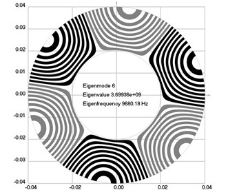
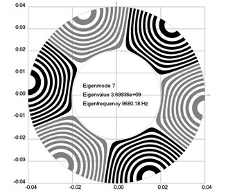
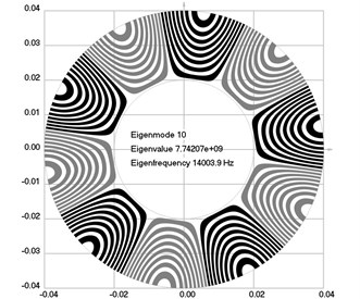
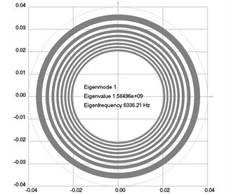
The geometry of the investigated structure is a circle having internal radius 0.02 m and external radius 0.04 m. It is assumed that all nodal displacements are equal to zero on the internal radius of the circle. The following parameters of the analyzed structure are assumed: modulus of elasticity 6×10⁸ Pa, Poisson’s ratio 0.3, density of the material of the investigated structure 785 kg/m3.
Fig. 1Eigenmodes of longitudinal motion when the investigated structure does not rotate: a) the first eigenmode, b) the second eigenmode, …, j) the tenth eigenmode

a)
b)
c)
d)
e)
f)
g)

h)

i)
j)
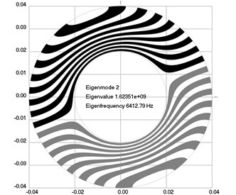
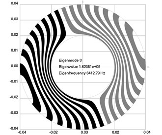
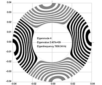
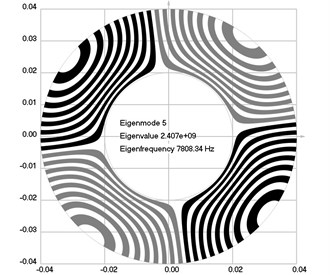
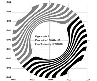
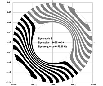
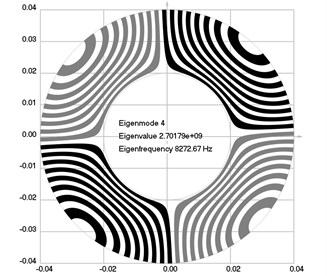
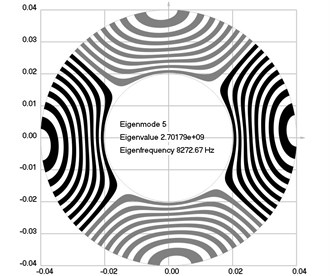
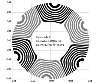
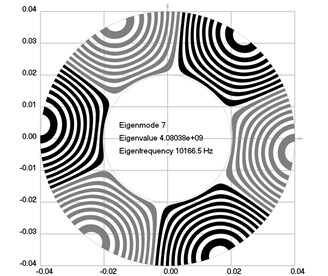
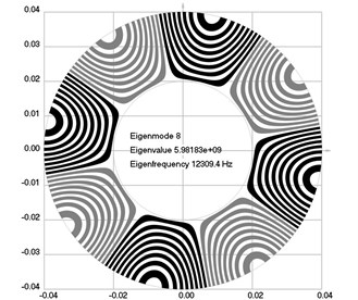
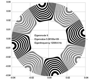
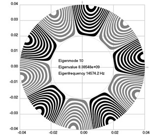
Fig. 2Eigenmodes of longitudinal motion when the investigated structure rotates: a) the first eigenmode, b) the second eigenmode, …, j) the tenth eigenmode
a)
b)
c)
d)
e)
f)
g)
h)
i)
j)
The first ten eigenmodes of longitudinal motion for 0 rad/sec are shown in Fig. 1.
The first ten eigenmodes of longitudinal motion for rad/sec are shown in Fig. 2.
From the presented results, the effect of supplementary stiffness because of the stresses caused by centrifugal forces to the eigenfrequencies of the analyzed structure is clearly seen.
4. Results of experimental investigations of dynamics of rollers
Laser head “Microtrack LTC 200-100” was used in the performed investigation. Dynamic processes of rollers and of their segments were measured by using this laser head. The simplest method to make the rollers rotate in the process of experimental investigation is to rotate them manually. So, in the performed investigation this approach was adopted. Data of performed measurements were transferred to the personal computer. Planning the experimental investigation involved the pre-selection of a number of points in which measurements were performed (see Fig. 3). The selection of measurement points and their locations were described in the previous papers of the authors. Low frequency filter was used in order to make the results of experimental investigations interpretable. In the earlier papers the authors did present the material related with the design of the proposed experimental setup and the process of experimental investigations in detail.
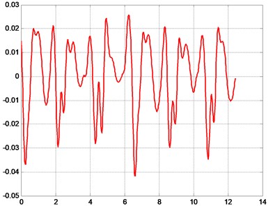
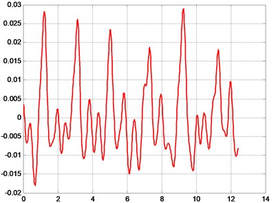
Some of the obtained typical results from the performed measurements of displacements at pre-selected points of the rollers are presented in Fig. 4.
Dynamical processes of complicated character are obtained as a result of performed measurements. The designed low pass digital filter after applying appropriate values of the parameters enables to obtain satisfactory correspondence with the results represented by the eigenmodes obtained numerically.
Fig. 3External view of 8 pockets of the folding machine and of the pre-selected points of measurements (17-20)
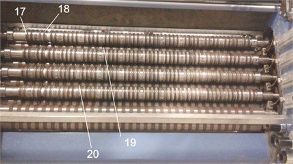
Fig. 4Typical results of measurements of displacements of rollers at some of the measurement positions
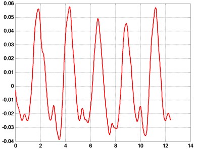
a) Pre-selected point number 17, displacement (mm) as a function of time (s)
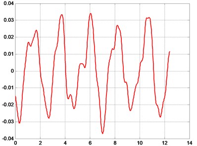
b) Pre-selected point number 18, displacement (mm) as a function of time (s)
c) Pre-selected point number 19, displacement (mm) as a function of time (s)
d) Pre-selected point number 20, displacement (mm) as a function of time (s)
5. Conclusions
Laser head “Microtrack LTC 200-100” was used in the performed investigation. Dynamic processes of rollers and of their segments were measured by using this laser head. The simplest method to make the rollers rotate in the process of experimental investigation is to rotate them manually. So, in the performed investigation this approach was adopted. Data of performed measurements were transferred to the personal computer. Planning the experimental investigation involved the pre-selection of a number of points in which measurements were performed. Low frequency filter was used in order to make the results of experimental investigations interpretable.
Plane strain problem is investigated and supplementary stiffness from the static loading caused by centrifugal forces is taken into account. Eigenmodes of longitudinal vibrations are investigated.
From the presented results, the effect of supplementary stiffness because of the stresses caused by centrifugal forces to the eigenfrequencies of the analyzed structure is clearly seen.
Dynamical processes of complicated character are obtained as a result of performed measurements. The designed low pass digital filter after applying appropriate values of the parameters enables to obtain satisfactory correspondence with the results represented by the eigenmodes obtained numerically.
The results presented in the paper are used in the design of folding machines, which have various types of rollers in them. Also, these results obtained during investigations allow to determine the time when it is necessary to carry out the renewal of obsolete rollers in order that the folding of printing products would be qualitative.
References
-
Ragulskis K., Ragulskis L., Kibirkštis E., Augutis S. V., Vainilavičius D., Miliūnas V., Pauliukaitis D. Measurement of vibrations of rotating elements in a folding machine. Journal of Measurements in Engineering, Vol. 3, Issue 1, 2015, p. 9-16.
-
Kibirkštis E., Augutis S. V., Vainilavičius D., Miliūnas V., Pauliukaitis D., Ragulskis L. Effect of dynamic regime of rollers of pocket folding machine to quality of printing products. Journal of Vibroengineering, Vol. 17, Issue 6, 2015, p. 2869-2881.
-
PeiponenK. E., Myllyla R., Priezzhev A. V. Optical Measurement Techniques – Innovations for Industry and the Life Sciences. Springer, 2009, p. 155.
-
Jayakumar T., Thavasimuthu M. Practical Non-Destructive Testing. Woodhead, Cambridge, 2002, p. 184.
-
Rastogi P. K. Optical Measurement Techniques and Applications. Artech House Incorporated, 1997, p. 433.
-
Technical Characteristics of Laser Displacement Measurement Head “Microtrack LTC 200-100”. http://mtiinstruments.com/pdf/products/microtrak2sal.pdf.
-
Bathe K. J. Finite Element Procedures in Engineering Analysis. Prentice-Hall, New Jersey, 1982.
-
Zienkiewicz O. C. The Finite Element Method in Engineering Science. Mir, Moscow, 1975, (in Russian).
-
Castro J., Ostoja Starzewski M. Elasto – plasticity of paper. International Journal of Plasticity, Vol. 19, 2003, p. 2083-2098.
-
Levy S., Wilkinson J. P. D. The Component Element Method in Dynamics with Application to Earthquake and Vehicle Engineering. McGraw-Hill, New York, 1976.
-
Huang H., Hagman A., Nygards M. Quasi static analysis of creasing and folding for three paperboards. Mechanics of Materials, Vol. 69, Issue 1, 2014, p. 11-34.
-
Barbier C., Larsson P. L., Östlund S. Numerical investigations of folding of coated papers. Composite Structures, Vol. 67, Issue 4, 2005, p. 383-394.
-
Barbier C., Larsson P. L., Östlund S. On dynamic effects at folding of coated papers. Composite Structures, Vol. 67, Issue 4, 2005, p. 395-402.
-
Barbier C., Larsson P. L., Östlund S. Experimental investigation of damage at folding of coated papers. Nordic Pulp and Paper Research Journal, Vol. 17, Issue 1, 2002, p. 34-38.
-
Sim K., Youn H. J., Oh K. D., Lee H. L., et al. Fold cracking of coated paper: the effect of pulp fiber composition and beating. Nordic Pulp and Paper Research Journal, Vol. 27, Issue 2, 2012, p. 445-450.
-
Dai J. S., Medland A. J., Mullineux G. Carton erection using reconfigurable folder mechanism. Packaging Technology and Science, Vol. 22, Issue 7, 2009, p. 385-395.
-
Yao W., Cannella F., Dai J. S. Automatic folding of cartons using a reconfigurable robotic system. Robotics and Computer – Integrated Manufacturing, Vol. 27, Issue 3, 2011, p. 604-613.
-
Mullineux G., Feldman J., Matthews J. Using constraints at the conceptual stage of the design of carton erection. Mechanism and Machine Theory, Vol. 45, Issue 12, 2010, p. 1897-1908.
-
Sirkett D. M., Hicks B. J., Berry C., Mullineux G., Medland A. J. Simulating the behavior of folded cartons during complex packing operations. Proceedings of the Institution of Mechanical Engineers, Part C: Journal of Mechanical Engineering Science, Vol. 220, Issue 12, 2010, p. 1797-1811.
-
Liu H., Dai J. An approach to carton – folding trajectory planning using dual robotic fingers. Robotics and Autonomous Systems, Vol. 42, Issue 1, 2003, p. 47-63.
-
Gidlöf V. In press conditions and their effect on runnability and convertability in digital package printing. Packaging Technology and Science, Vol. 18, Issue 4, 2005, p. 189-197.
About this article

The work was carried out on the basis of the Contract No. F5-90-1389.
