Abstract
In order to get further study for the effect of abrasive grains to the wall of the workpiece during polishing process, a new method of discrete element that carry out the numerical simulation with DEM is put forward, and the visual calculation is performed for the abrasive grain movement in the nozzle. The interaction of particles-particles or particles-workpiece wall during the polishing process and the tracks of single grain in the workpiece are analyzed by observing the distribution of abrasive grain in the workpiece at different time. The surface removal mechanism of abrasive grains to the workpiece material is discussed by analyzing the collision process of particles to the workpiece wall. The wear level of the abrasive grains to the inner surface of the workpiece is studied through the force of abrasive grain to the workpiece wall consumption, and finally explore the cutting effect of particles to workpiece wall. As a consequence, the abrasive flow processing experiment is carried out. The surface roughness of the large hole and small hole of the nozzle are detected by stylus measurement. The conclusion shows that the surface roughness for the large hole and the small hole before the experiment is1.741 μm and 1.201 μm, its 0.801 μm, 0.651 μm after it. Further roughness tests are performed on the surface of the pores by means of a grating surface measuring instrument. The result indicates that the surface roughness reduces from 2.67 μm to 0.697 μm, 0.728 μm, 0.782 μm. Apparently, the surface roughness of the hole is sharply reduced, which has a smooth and flat inner surface, the effectiveness and reliability of the abrasive flow are verified.
1. Introduction
The nozzle is one of the most important and critical parts of the engine, whose function is that put the diesel or gasoline into the cylinder through the nozzle, and start the engine by the high-pressure injection, the oil atomization, spark plug ignition [1-4]. It is easy to cause the nozzle blocked and thus put the performance in a bad condition once there is burr or not smooth enough. Therefore, the high internal surface processing accuracy must to be needed. The internal surface size of the nozzle parts is relatively small, the processing methods of the injector are generally processed by traditional processing such as laser drilling, EDM, electrochemical processing and so forth. The processing quality of the parts is difficult to reach what we need with that way. So, the processing quality and efficiency cannot meet what we expect. However, abrasive grain polishing technology can effectively solve the traditional processing methods that cannot do [5-11].
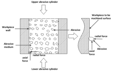
Abrasive flow machining is a technology whose purpose is to remove the material, which based on the particles for the tool, the fluid as the carrier, through the flow of fluid in the surface of the components to promote the particles to produce slip friction and collision in the workpiece surface. Abrasive flow is able to promote in the workpiece surface relative movement by the hydraulic cylinder drive piston to move up and down under pressure. After that, the workpiece surface gets a greater shear force, which can achieve the surface material micro-removal to reach the purpose of polishing. Affected by the fluid turbulence state, the abrasive grains in the channel will be worked from every direction of the liquid phase. Consequently, disorderly action will be shaped in the cavity. The change of the surface quality of the workpiece is the result of the joint action of the various stresses, mainly by the micro-cutting effect caused by the relative movement of the abrasive grains and the workpiece. The force diagram of abrasive grains in the workpiece flow path is shown in Fig. 1 [12-16].
Discrete element method is a kind of particle dispersion material analysis method proposed by American scholar Cundall P. A. in 1971 based on the molecular dynamics principle, whose basic idea is to separate the discontinuous body into a set of rigid elements so that each rigid element satisfies the equation of motion, and then the motion equation of each rigid element will be settled with iterative method, and then the whole motion form of the discontinuity is obtained [17-20]. The polishing essence of the abrasive grains is the collision and cutting of the numerous particles to the wall. Therefore, the polishing process of the abrasive grains can be analyzed and calculated though the discrete element method.
Fig. 1The force diagram of abrasive grains in the workpiece runner
2. Discrete element theory
2.1. Particle model of discrete element method
The discrete element method regards the analysis object as a number of discrete elements. Each particle is a unit. The contact force is calculated according to the interaction between the particles at any time in the whole procedure. Then the motion parameters of the unit are computed by Newton’s law of motion, which alternately and repeat operate to achieve the prediction of the movement of the object.
There are different particle models and the calculation methods according to the different means of processing problems. Generally speaking, it has two types: hardball model and soft sphere model. The former is mainly used to simulate the particles situation in the Kutel flow and comparatively fast shear flow. The collision between the particles is instantaneous, Dramatic plastic deformation cannot be happened by itself in the course of the collision, so only the collision of two particles are considered rather than three or more. The latter is chiefly used to simulate the collision process between two particles, and even two or more particles colliding at the same time. The collision between them occurs over a period of time, the contact force between the particles can be calculated to obtain on the basis of using Newton's second law according to the amount of overlap.
2.2. Particle contact model
The motion of the particles in the particle model is independent of each other and only interacts at the point of contact when the contact occurs. And the discretization of the particles pushes it produce perplexed movement whatever it’s underload or not. There is most common particle model:
(1) Cundall’s DEM contact model.
(2) Thornton’s three-dimensional sphere dry contact model.
(3) DEM improved model.
• Oda’s improved discrete element method.
• Kishino’s granular element method.
(4) Non-circular or non-spherical DEM dry contact model.
(5) Model of wet particles acting on interstitial fluid.
3. Numerical analysis of the quality of abrasive flow polishing nozzle with discrete element method
3.1. Particle-particle interaction
The abrasive grains get exceedingly irregular because of the impact between abrasive grains so that the number of collisions between the abrasive grains and the wall will increase, which is beneficial to the cutting effect of the abrasive grains on the wall of the workpiece, and hence achieve the finishing. The abrasive grain is simplified into a spherical model for the sake of applying discrete element method, and a random collision occurs between the abrasive grains. Assuming that the abrasive grain motion is disordered, the velocity before and after the collision is shown in Fig. 2. It can be seen from the figure that the direction of movement of the abrasive grains before and after the collision changes.
The numerical simulation time of the discrete grain movement is set to 1 s, the Rayleigh time step is set to 30 %, the abrasive concentration is 20 %, the abrasive grain velocity is set to 30 m/s. From the beginning to the end, the histogram that the number of abrasive grains in the workpiece changes with time is shown in Fig. 3.
Fig. 2The collision between abrasive grains
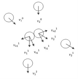
Fig. 3The histogram of the number of abrasive grains in the workpiece changes with time
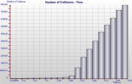
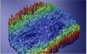
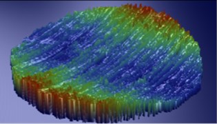
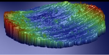
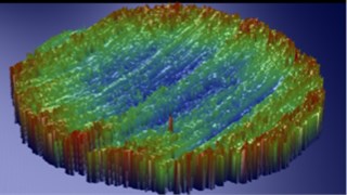
It can be inferred from Fig. 3 that the number of abrasive grains increases gradually. And the granule increases slowly at 0-0.5 s, because the abrasive grains gradually enter the workpiece cavity and slowly fill, but sharply increases at 0.5-1 s, which because the hole suddenly gets small, the grain is resisted in the workpiece cavity, so the abrasive grain will gather inside the workpiece, The simulation processing was realized after between the collision of abrasive grains and the abrasive grains with the workpiece, ultimately, it flows out of the workpiece, The process of abrasive grain movement at different times is shown in Fig. 4.
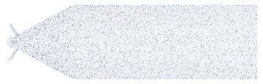
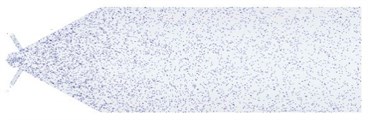
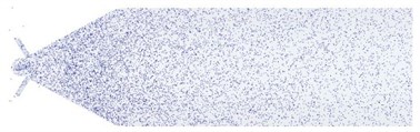
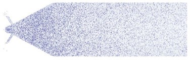
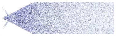
It can be deduced from Fig. 4 that when the numerical simulation is 0.1 s, the abrasive grains have just entered the workpiece, and the number of abrasive grains is relatively small, which mainly distributed in the large hole of the workpiece. At 0.2-0.4 s, the whole workpiece cavity is filled by the abrasive grains, and the abrasive grains are in a scatter condition and have less chances to collide. At 0.6 s, the abrasive grains in the front part of the workpiece start to gather, and some of which begin to flow out of the hole. The hole wall is well polished after the abrasive grains crash with the wall of the small hole for many times. while at 0.6-1.0 s, abrasive grains velocity gradually reduce in that majority of the abrasive particles are colliding in processing. and in the end, the final speed becomes 0 m/s. Therefore, abrasive grain in the front of the workpiece will be deposited so that there is no way to flow out of the workpiece. A conclusion can be easily drawn that Cleaning the workpiece is the most essential procedure after polishing. A numerical simulation analysis with a particle picked out from grains at random is executed for the sake of the further research. There are four particles to be conducted visual numerical simulation analysis as shown in Fig. 5.
Fig. 4The process of abrasive grain movement at different times
a) 0.1 seconds for the abrasive movement
b) 0.2 seconds for the abrasive movement
c) 0.4 seconds for the abrasive movement
d) 0.6 seconds for the abrasive movement
e) 0.8 seconds for the abrasive movement
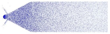
f) 1.0 seconds for the abrasive movement
Fig. 5The paths of different particles

a) Abrasive 1 motion trace

b) Abrasive 2 motion trace

c) Abrasive 3 motion trace
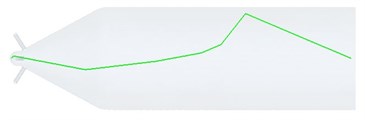
d) Abrasive 4 motion trace
From the picture, we know that the movement of the abrasive grains is out of order as a result of the collision between abrasive grains and the wall and itself. The more violent the collisions get, the more opportunities of collision abrasive grains and wall have, the better the polishing effect is. So, pressure increases, speed rises, the collision is more severe, the higher material removal can be attained. Also it can be seen that part of abrasive grains flow out of the hole while some just remain in the hole, because a number of kinetic energy is consumed by means of collisions and fluid resistance during abrasive particles flow into the workpiece cavity. When it touches the front of the workpiece, it’s speed gradually slowed down until speed is zero, in consequence, the deposition will be formed in the front of the workpiece, On the contrary, some just flow out, and material removal is realized.
3.2. Analysis of surface removal mechanism of single particle blast
Based on the analysis of the flow pattern of the abrasive grains in the workpiece, the vertex can be produced because of changes of the pore size when abrasive grains flow into the small holes of the workpiece. The workpiece wall will be received frequent impact once eddy is made, which can effectively polish it. The movement of the particles is raised with the motion of the abrasive. The surface morphology is well shown though frequent collision giving rise to the removal of material between wall and particle driven by slurry.
In the process of numerical simulation, the abrasive grains are assumed to be spherical. Due to the contact area between the abrasive grains and the workpiece is very limit during the collision, Therefore, it can be regarded as a plane [21]. The model and grid of the single-particle collision are shown in Fig. 6.
The workpiece material used in the numerical calculation is stainless steel, the abrasive grains are silicon carbide, whose parameters used in this paper are shown in Table 1.
Fig. 6Single particle collision model grid
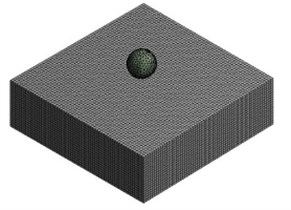
Table 1Workpiece and abrasive material parameters
Material science | Density / (kg/m3) | Elastic modulus / (GPa) | Poisson ratio / (v) |
Stainless steel | 7930 | 200 | 0.29 |
Sic | 2975 | 322 | 0.142 |
In the numerical calculation process, the abrasive grain velocity is 30 m/s, and it is found that the turbulent condition of the abrasive flow can be satisfied according to the analysis. A research that the process of single particle collision with the wall of the workpiece is carried out in order to clearly analyze the change of the surface of the workpiece after machining in this paper. The equivalent stress and total deformation of the workpiece surface after the calculation is completed are shown in Fig. 7.
Fig. 7The equivalent stress and total deformation of the workpiece surface
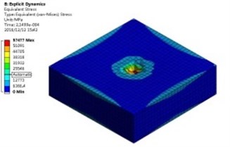
a) The equivalent stress
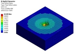
b) The total deformation
As shown here, it can be found that the equivalent stress focuses on the center of the collision, which is produced by the abrasive collision and start to change in the workpiece surface, and the deformation also reaches its maximum at the same time. In order to be able to more clearly and intuitively analyze the force and deformation of the workpiece surface after the abrasive bearing, the middle position of the model is chosen to observe the equivalent stress and deformation of the workpiece at different collision times. As shown below.
Fig. 8Equivalent stress distribution of workpiece at different moments
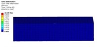
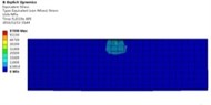
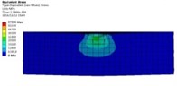
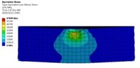
Fig. 9Workpiece deformation at different moments
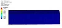

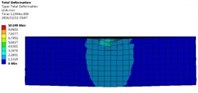
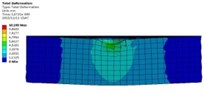
It can be obtained from Fig. 8 and Fig. 9 that the stress and deformation of the workpiece surface are obviously changed after impacting. The plastic Deformation in the workpiece will be appeared when the abrasive grains are exposed to the surface of the workpiece in the polishing process. With the deepening of the collision, the plastic deformation is also increasing, when the abrasive particles from different directions at different speeds frequently hit the same position on the workpiece, the workpiece material will continue to be in different directions Shear force. In the collision process, the force perpendicular to the surface leads to the abrasive grains to be squeezed into the surface of the workpiece. The tangential force parallel to the machined surface gives rise to the abrasive grains to slide relative to the workpiece. During the sliding process, the lattice inside the material will produce dislocations. As the number of squeeze slides increases, the workpiece material is irreversibly plastically deformed. And eventually removed as the deformed area becomes larger, and the burrs on the workpiece surface finally break and flow out of the workpiece with abrasive particles.
Through the equivalent stress curve on the surface of the workpiece in Fig. 10, it can be learned that the stress change on the surface of the workpiece is pretty obvious after the impact of the abrasive grains. The stress rapidly increases in the first collision state, which mainly because that the abrasive grains crash the wall at a high speed so that there is a quick stress increase on the surface of the workpiece. Nevertheless, it begins to decrease gradually when the stress reaches its maximum and eventually remains constant, which manifest that the workpiece subjected to abrasive crash has been up to its maximum plastic deformation.
Fig. 10The equivalent stress curve of workpiece surface
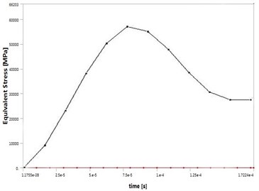
Fig. 11The line graph of geometry under total pressure
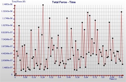
To explore the total force of the abrasive grains on the geometry, the line graph of Fig. 11 is obtained by numerical simulation.
The wear degree of the abrasive grains on the inner surface of the workpiece can be proved by the total strength of the abrasive grains on the inner surface of the workpiece. It can be seen from Fig. 11 that there will appear unstable force on the internal surface of the workpiece, signifying that the abrasive grains are irregular, the impact force of the wall by the abrasive is also different at different times, and the collision times of abrasive particles on the wall and abrasive wear on the workpiece is also different.
4. Experimental research of the quality of polishing nozzle based on discrete element method
In this experiment, four workpieces are selected to mark the original 1#, 2#, 3# and 4#respectively. The last three are polished at 30 m/s. The polishing effect abrasive grains to the workpiece will be greatly affected by the choice of abrasive in the polishing process, so it’s indispensable that the abrasive is made up of particles the same size and hardness and specifications and the same viscosity slurry carrier. And there are three kinds of common particles such as silicon carbide and boron carbide or aluminum oxide.
The silicon carbide whose size is 8 μm is choose to be Grinding particles in this experiment. The main components of the grinding fluid consist of hydraulic oil and contained a small amount of triethanolamine. And the final concentration is 20 %.
When polishing, the abrasive flow into the workpiece with a vertical angle. The nozzle hole, whose diameter is 0.16 mm, relatively small, needs to be cut so as to analyze the effect of the inner surface of the workpiece before and after polishing. Physical map of nozzle can be got before and after cutting as shown in Fig. 12.
Fig. 12Before and after cutting
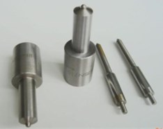
a) Before cutting
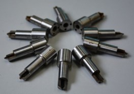
b) After cutting
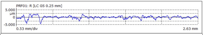
The nozzle needs to be washed after cutting for testing the surface quality. In this paper, 2000 Hz ultrasonic oscillator is applied to clean it. The procedure is: a little zinc oxide and alcohol are added to remove the surface stains and anti-oxidation measures are also formed, then put it into the oven and dry it out. And right now, the detection could be done. To gain better check consequence, the big and small hole are examined for surface roughness. The results are shown in Fig. 13 and Fig. 14.
After the above detection, the surface to be big hole and small hole, the original 1# sample 2#, sample 3# and sample 4# roughness, Specific data shown in table 2.
Table 2Test values of surface roughness at large and small holes
Surface roughness of large pores / (μm) | Surface roughness of small hole / (μm) | ||||||
Original 1# | Sample 2# | Sample 3# | Sample 4# | Original 1# | Sample 2# | Sample 3# | Sample 4# |
1.741 | 0.773 | 0.800 | 0.830 | 1.201 | 0.661 | 0.619 | 0.672 |
As can be seen from Table 2, the measuring results of the original 1# in the large hole and the small hole are 1.741 μm and 1.201 μm respectively. The results of the measurement after the processing indicate that the amplitude of the fluctuation is small. And the maximum value are 0.830 μm and 0.672 μm, which disclose that the processing effect is clearly enhanced, and the processing accuracy has increased one level.
Fig. 13The surface roughness of small hole
a) Original 1 #
b) Sample 2 #
c) Sample 3 #
d) Sample 4 #
Fig. 14The surface roughness of big hole
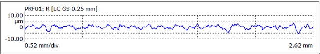
a) Original 1 #
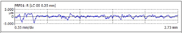
b) Sample 2 #
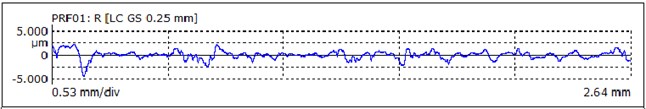
c) Sample 3 #
d) Sample 4 #
By comparing the surface roughness of the pores with the macropores, it can be inferred that the former is better than the latter, it’s because the macroporous fluid pressure is less than the pore, thus the precision of large hole can be improved by adding core to the flow path, reducing the flow path space and promoting the fluid pressure. The detection of surface roughness confirms the effectiveness of abrasive grain flow processing.
To better analyze the surface morphology of the pores at the cross hole before and after the processing, the scanning electron microscopy is used to check it. As the pictures shown below.
Fig. 15Scanning electron microscopy at the cross hole
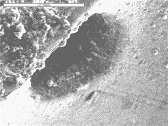
a) Original 1#
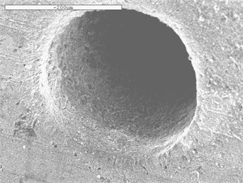
b) Sample 2#
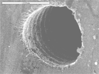
c) Sample 3#
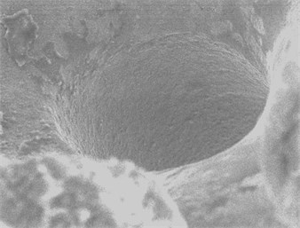
d) Sample 4#
Fig. 16Three-dimensional scanning of surface roughness before and after machining
a) Original 1#
b) Sample 2#
c) Sample 3#
d) Sample 4#
It shows that the original 1#, whose edge has more burrs, has uneven inner surface and not smooth. But The processing effect of nozzle is extremely boosted after polishing. The burr phenomenon at the cross hole can be eliminated by abrasive flow processing technique, and it also can make the uneven surface smooth, effectively improve the inner surface quality of the injector.
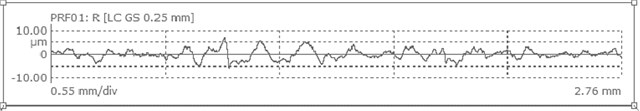
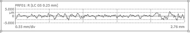
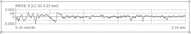
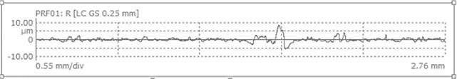
In order to be able to more accurately and intuitively analyze the effect of abrasive grains to the polishing effect of the elbow, a further surface roughness examination is performed by the grating surface roughness meter. As shown in Fig. 16.
It can be concluded from Fig. 16 that the internal surface of the nozzle is filled with burrs before processing. The roughness of the original 1# is respectively decreased from 2.67 μm to 0.697 μm, 0.728 μm, 0.782 μm. The surface roughness is obviously reduced. The reliability and validity and practicability of abrasive flow polishing technology are verified.
5. Conclusions
1) Based on the study of solid-liquid two-phase abrasive polishing nozzle with discrete element method, the particle model and theory are described. Through the numerical simulation of DEM, the collision of particle-particle and particle-wall during the simulation process was analyzed. The distribution of abrasive grains in the workpiece was observed at different time, and the movement trajectory of single abrasive grain in the workpiece was explained. And the mechanism of surface removal of single grain collision was discussed. In addition, the effect of abrasive grains on the wall consumption of the workpiece is illustrated.
2) Based on the experimental study on the solid-liquid two-phase abrasive flow, the surface roughness of the nozzle at the macropore and the small hole were measured respectively. The surface roughness was dropped from 1.741 μm and 0.201 μm to 0.801 μm and 0.651 μm by Abrasive flow processing. The surface morphology of the workpiece was observed by use of scanning electron microscopy, the effect of deburring before and after the abrasive flow working was analyzed by high-power microscope. A further surface roughness examination is performed by the grating surface roughness meter, and found that the roughness of the original 1# is respectively decreased from 2.67 μm to 0.697 μm, 0.728 μm, 0.782 μm. The reliability and validity and practicability of abrasive flow polishing technology are confirmed.
References
-
Liu Weina, Cai Zhijie, Li Yunfeng, et al. Numerical simulation and experiments of abrasive flow polishing for nozzle micro-holes. China Mechanical Engineering, Vol. 28, Issue 1, 2017, p. 13-19,26.
-
Ji Shiming, Qiu Yi, Cai Yaojie, et al. Research on mechanism of ultrasound enhancing and the experiment based on softness abrasive flow. Journal of Mechanical Engineering, Vol. 7, 2014, p. 84-93.
-
Li Junye, Dong Kun, Wang Xinghua, et al. Molecular dynamics simulation research into generative mechanism of particles micro-cutting surface. Journal of Mechanical Engineering, Vol. 17, 2016, p. 94-10.
-
Li Junye Yang Lifeng Liu Weina, et al. Experimental research into technology of abrasive flow machining nonlinear tube Runner. Advances in Mechanical Engineering, Vol. 6, 2015, p. 752353-752353.
-
Li Chen, Shan Yingying, Li Zhian, et al. Measurement of softness abrasive flow field based on particles image velocimetry. Transactions of the Chinese Society of Agricultural Engineering, Vol. 5, 2015, p. 71-77.
-
Jain V. K., Jayswal S. C., Dixit P. M. Modeling and simulation of surface roughness in magnetic abrasive finishing using non-uniform surface profiles. Materials and Manufacturing Processes, Vol. 22, Issue 2, 2007, p. 256-270.
-
Li Junye, Wang Binyu, Wang Xinghua, Zhang Xinming Based on the Molecular dynamics of particles in micro grinding numerical simulation. Journal of Computational and Theoretical Nanoscience, Vol. 13, Issue 11, 2016, p. 8652-8657.
-
Bremerstein T., Potthoff A., Michaelis A., et al. Wear of abrasive media and its effect on abrasive flow machining results. Wear, Vol. 342, Issues 343-15, 2015, p. 44-51.
-
Ji Shiming, Huang Xihuan, Tan Dapeng, et al. Gas-liquisolid abrasive flow polishing and its process parameter optimization. Optics and Precision Engineering, Vol. 24, Issue 4, 2016, p. 855-864.
-
Droubi M. G., Reubenr L. Monitoring acoustic emission (AE) energy of abrasive particle impacts in a slurry flow loop using a statistical distribution model. Applied Acoustics, Vol. 113, 2016, p. 202-209.
-
Ji Shiming, Li Jun, Tan Dapeng Numerical and experimental study on softness abrasive flow finishing based on turbulence enhancement by ultrasonic vibration. Journal of Mechanical Engineering, Vol. 21, 2016, p. 182-189.
-
Venkatesh G., Tarlochan Singh, Apurbba Kumar Sharma, Akshay Dvivedi finishing of micro-channels using abrasive flow machining. Springer India, Vol. 4, 2014, p. 243-252.
-
Ding Jinfu, Liu Runzhi, Zhang Kehua, et al. Micro cutting mechanism of abrasive flow precision machining. Optics and Precision Engineering, Vol. 12, 2014, p. 3324-3331.
-
Xie Yang, Lou Qiyuan, Ma Jian, et al. Numerical simulation and experimental validation of internal nozzle flow characteristic of injector. Journal of Zhejiang University (Engineering Science), Vol. 50, Issue 1, 2016, p. 111-115.
-
Ji Shiming, Ma Baoli, Tan Dapeng Numerical analysis of soft abrasive flow in structured restraint flow passage. Optics and Precision Engineering, Vol. 19, Issue 9, 2011, p. 2092-2099.
-
Li Junye Yang Lifeng Liu Weina, et al. Numerical thermodynamic analysis of two-phase solid-liquid abrasive flow polishing in u-type tube. Advances in Mechanical Engineering, Vol. 2014, 2014, p. 1-17.
-
Bian Xiaolei, Hou Yajuan, Zhao Mei, et al. DEM and its application to particle pulverization. Mining Machine, Vol. 6, 2015, p. 62-67.
-
Gao Hang, Wu Mingyu, Fu Youzhi, et al. Development of theory and technology in fluid abrasive finishing technology. Journal of Mechanical Engineering, Vol. 7, 2015, p. 174-187.
-
Zhou Difeng, Liu Dongyu Coupling DEM-CFD double inlet abrasive flow dynamics of numerical simulation and test device. Journal of Mechanical and Electrical Engineering, Vol. 12, 2013, p. 1467-1471.
-
Xu Yong, Sun Qicheng, Zhangling, et al. Advances in discrete element methods for particulate materials. Advances in Mechanics. Vol. 2, 2003, p. 251-260.
-
Wang Jiaqi Research on Particles in Soft Abrasive Flow Colliding with the Structural Surface. Zhejiang University of Technology, 2012.
Cited by
About this article

The authors would like to thank the National Natural Science Foundation of China No. NSFC 51206011, Jilin Province Science and Technology Development Program of Jilin Province No. 20160101270JC and No. 20170204064GX, Project of Education Department of Jilin Province No. 2016386. At the same time, thanks for the Hi-Key Technology Company to provides a trial version of EDEM software.
